decon E-Drive PLUS User manual

E-Drive PLUS
4FSWJDFmanual
#SVLBSNBOVBMWFSTJPO

Foreword
This Service Manual describes the procedures for inspecting, adjusting, and assembling the E-Drive PLUS,
as well as how to handle errors.
Symbols Used in This Manual
Items concerning proper handling are indicated with the following symbols.
Other Precautions
• For product improvement purposes, the descriptions and specifications in this manual are
subject to change without notice.
• Due to changes in the specifications, some of the photos and descriptions may differ from
the actual product.
• This manual is intended for use by persons possessing the basic technical knowledge and
skills.
• Persons who do not possess the general service skills and knowledge should not rely solely
on this service manual to perform inspection, adjustment, disassembly, or reassembly.
Failure to observe this precaution can lead to maintenance problems or mechanical dam-
age.
NOTICE
Indicates that misuse may lead to material damage.
Indicates correct methods and key points when operating the
product.
WARNING
Indicates that misuse may lead to fatal or severe injury, or
disability.

Table of Contents
1. Product Overview 5
1.1. Product Features 5
1.2. Variations 6
2.
Wheelchair Frame Conditions for Installing the E-Drive PLUS
7
2.1. Strength Conditions 7
2.2. Structure Conditions 7
2.3. Functional Conditions 8
2.4. Other 8
2.5. Assistant Controller 9
3. Installation Procedure 10
3.1. Supplied Parts Check 10
3.2. Power Unit Installation 17
3.3. Separate Battery Seat Installation 22
3.4. Controller Installation 23
3.5. Anti-tip Device Adjustment 31
3.6. Clutch Lever Position Adjustment 32
3.7. Wheel Cap Installation (20", 22" and 24" Models) 32
3.8. Check Items after Power Unit Installation 33
4.
Optional Part Installation and Adjustment Procedures
34
4.1. Battery Seat Oset Parts 34
4.2. Joystick Knob and Return Spring Replacement 37
4.3. Power Switch and Speed Switch Replacement 41
4.4. Hand Rim Replacement (20", 22", and 24" Models) 43
4.5. Wheel Cap Replacement (20", 22", and 24" Models) 44
5.
Installation, Removal, Disassembly, Assembly, and Adjustment Procedures of Each Part
46
5.1. Wheel Assembly Removal and Installation 46
5.2. Drive Unit Removal and Installation
(Fixed Axle Models) 47
5.3. Motor Control Unit (Printed Circuit Board) Removal
and Installation 48

5.4. Wire Harness and Lead Wire Removal
and Installation 50
5.5. Clutch Lever Removal and Installation
(20", 22" and 24" Models) 50
5.6. Clutch Switch Adjustment 52
5.7. Controller Removal, Installation, and Position
Adjustment 52
5.8. Switching the Controller Left/Right Side Position 54
5.9. Controller Disassembly, Assembly, and Parts
Replacement 57
5.10. Assistant Controller (Option) Disassembly
and Assembly 59
6. Settings the Parameters 60
6.1. Operation Overview 60
6.2. Driving Parameters ~Preset Mode~ Setting Method 63
6.3. Driving Parameters ~Free Mode~ Setting Method 65
6.4. Function Parameters Setting Method 73
6.5. Method for Restoring Factory Settings 77
7. Other Settings 78
7.1. Joystick Range of Motion Adjustment 78
7.2. Anti-tampering Function Setting 80
8. Warnings 82
8.1. List of Warnings 82
9. Self-Diagnosis 85
9.1. Self-Diagnosis Function 85
9.2. List of Detected Malfunctions 85
9.3. History Display of Detected Malfunctions Using the
Self-Diagnosis 91
10. Inspection and Maintenance 93
10.1. Inspection Item 93
11. Specications and Other Information 94
11.1. Table of Specications 94
11. 2. W ir in g D iag ra m 9 8

5
1
1.
Product Overview
1.1. Product Features
1 Drive unit with AC servo flat motor.
2 Joystick controller.
3 Dedicated battery with built-in microcomputer.
(Nickel metal hydride battery or lithium ion battery)
4 Assistant controller (optional)
Example of installed E-Drive PLUS
1
3
4
2

6
1
1.2. Variations
(1) Power Unit for Wheelchairs
Model E-Drive PLUS
Tire size 20", 22" and 24" 16"
Controller Left {{
Right {{
Controller mounting Standard {{
Swing out {{
Speed 4.5 km/h type {{
6.0 km/h type {{
Mounting brackets
Cramp bracket {–
Bracket A – {
Bracket B – {
Battery seat Integrated {{
Separate – {
Battery location (when
using the integrated
battery seat)
No offset {{
Offset (28.5 mm) {{
Battery types
Nickel metal hydride
battery {{
Lithium ion battery {{
Assistant controller
(optional, right-hand
operation only)
Assistant controller
included {{

7
2
2.
Wheelchair Frame Conditions for Installing the E-Drive PLUS
WARNING
Do not install the E-Drive PLUS on a wheelchair frame that has insufficient strength.
Do not install the E-Drive PLUS on a wheelchair frame that does not meet the installation condi-
tions. Even if it can be installed on the frame, it may malfunction during use if the conditions are
not met, which could injure the user.
2.1. Strength Conditions
2.2. Structure Conditions
In order to ensure that the entire wheelchair has sufficient strength, the wheelchair frame on which
the E-Drive PLUS is installed must meet the following conditions.
The wheelchair frame must have the following structure.
(1) It must have strength equivalent to that required by JIS standards (T9203).
(2) The axle sleeve bracket is securely installed and does not have any looseness.
(3) It must not have a camber angle.
(4) It must have sufficient strength. (There is the chance that wheelchair frames that have
been used for a long time will lose some of their strength.)
(5) It must not have a camber angle.
(6) It must have sufficient strength.
(There is the chance that wheelchair frames that have been used for a long time will lose
some of their strength.)
(1) The diameter of the axle hole is 12.5 to 13.5 mm. (Fixed type case)
(2) The location that the nuts are in contact with around the axle hole must be flat and have
a sufficient surface area. (Fixed type case)
(3) The distance from the center of the axle hole to the base pipe must be at least 70 mm (16"
model bracket A case) or 80 mm (20, 22, 24" model case)
(4) The back pipe diameter must be ø22, and the height of the square lock portion from the
axle hole center must be 20 mm or shorter. (16" model bracket B case)
(5) When attached, the wheelchair frame and the E-Drive must not interfere with each other.
• If installing the adjustment washers in the shaft in order to prevent interference, use up
to 3 per side.
16" Model
[Bracket A] [Bracket B]

8
2
2.3. Functional Conditions
The wheelchair on which the E-Drive PLUS is installed must have the following functions in order to
ensure an appropriate sitting position.
(1) The suitable size of the wheels must be 16, 20, 22 and 24 inches.
(2) Parking brakes must be installed and adjusted to the proper position for the tires. When the E-Drive
PLUS is installed, it must be able to stop the wheelchair at a forward-reverse angle of 7 degrees
when the parking brakes are applied.
(3) When the E-Drive PLUS is installed, a forward-backward tip angle of at least 20 degrees and a side
tip angle of at least 15 degrees must be ensured. (See diagram below) A backward tip angle of at
least 25 degrees is recommended.
(4) Please ensure that the functions of the wheelchair frame are not impaired when the E-Drive PLUS
is installed.
Examples) The movable arm supports can move, the folding feature, reclining feature,
and parking brakes are functional, etc.
2.4. Other
Front casters at least 7 inches in diameter are recommended.
During power driving, operations like caster lifting are not possible. If the casters are small, it is
difficult to get over large bumps. The impact is also greater if the casters are small.
Large diameter (easy to get over bumps) Small diameter (difficult to get over bumps)
9
2
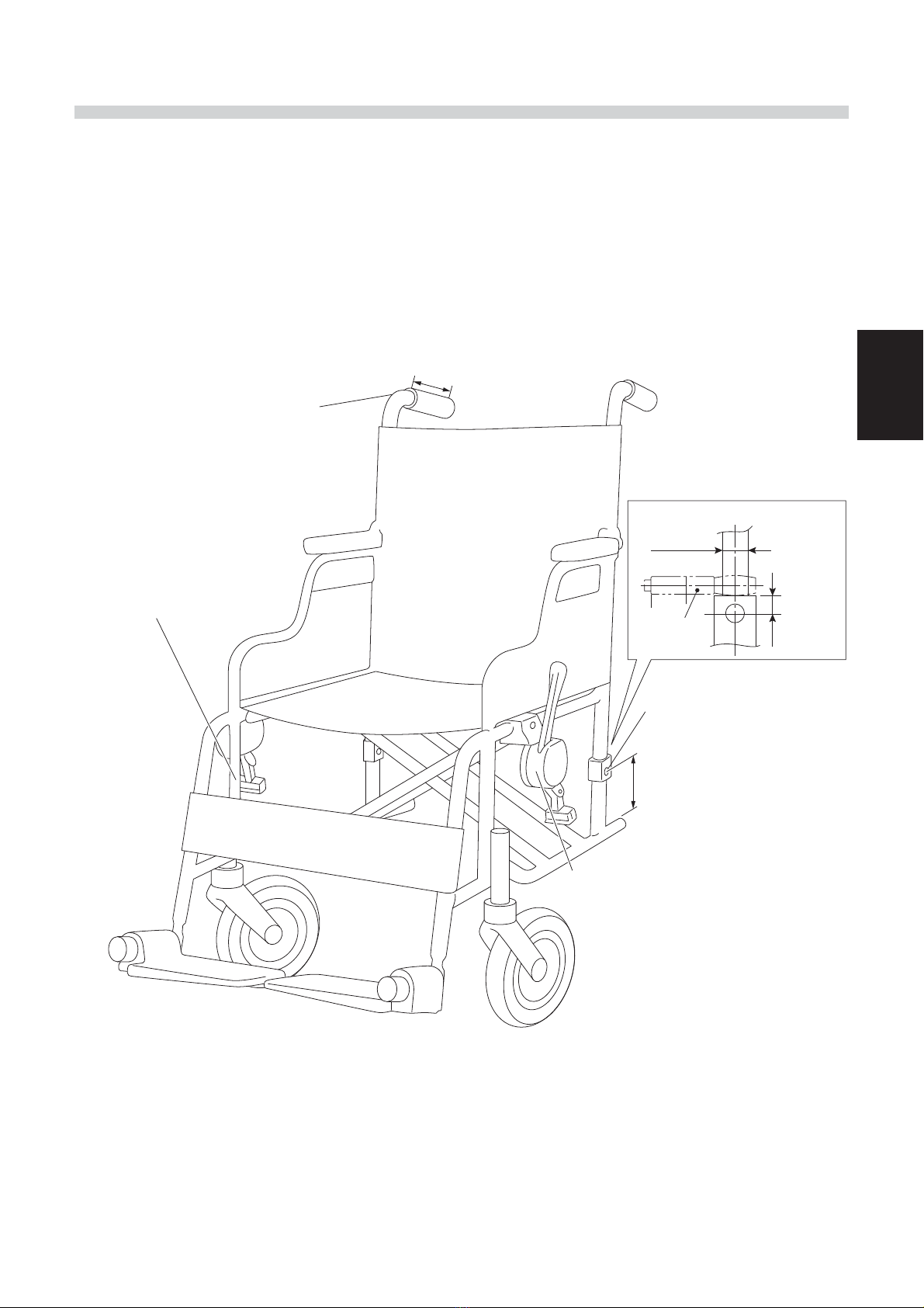
2.5. Assistant Controller
If installing the optional assistant controller:
(1) The push grip pipe must have a maximum outer diameter of 22 mm.
(2) The push grip pipe must have a minimum inner diameter of 16 mm.
(3) The straight section from the end of the push grip pipe must be 90 mm or longer.
Attaching the assistant controller
Maximum outer pipe diameter 22 mm
Minimum inner pipe diameter 16 mm
Straight section 90 mm or longer
Attaching the controller
Under holder attachment
Pipe diameter ø22, ø19, ø16 mm
Straight section
When using bracket B
ø22 mm
Bracket B
Maximum
20 mm
Wheel hole diameter
ø12.5-13.5
(Fixed type case)
When using bracket A
At least 70 mm to base pipe
When the parking brakes are installed on
E-Drive PLUS models, you can adjust and
move them to the proper position for
16-inch tires.
Front casters with a minimum
size of 7 inches
(recommended)

10
3
3.
Installation Procedure
3.1. Supplied Parts Check
(1) Standard Supplied Parts
3.1.1. Supplied Parts Check for 20", 22" and 24" Models
Product Name Remarks Quantity
1Left drive unit assembly 1
2Right drive unit assembly 1
3Large clamp For securing the wire harness 2
4Small clamp For securing the wire harness 2
5Spiral tube For protecting the wire harness 1
6Sticker For affixing to the manual and power
drive positions 3 each
7Supplied tools Two 8×10 mm open-end wrenches, and
one 5 mm hexagon wrench 1
8Clamp For securing the wire harness 18
9Controller assembly 1
:Plate assembly 1
AWheel cap Installed to the drive units 2
12
89
7
3
4
5
6
10
11
11
3
Product Name Remarks Quantity
1Upper holder assembly For installing the controller 1
2Under holder assembly For installing the controller 1
3Side plate for ø19–20 For installing the under holder 4
4Side plate for ø16–17 For installing the under holder 4
Product Name Remarks Quantity
1Left clamp bracket For installing the drive unit 1
2Right clamp bracket For installing the drive unit 1
3Plate washer For adjusting the outward position of
the drive unit 6
Product Name Remarks Quantity
1Swing out bracket For installing the controller 1
(2) Controller Installation
(3) Battery Location
[Standard]
[No Offset]
[Swing Out Bracket]
1 2 3 4
1
1 3 2

12
3
[Offset]
Battery Seat Offset Parts (Optional)
28.5 mm Offset
1
32
4 6 5
Product Name Remarks Quantity
1Spacer 28.5 mm 4
2Flange bolt 40 mm 1
3Flange bolt 45 mm 3
4Left clamp bracket For installing the drive unit 1
5Right clamp bracket For installing the drive unit 1
6Plate washer For adjusting the outward position of
the drive unit 6

13
3
(1) Standard Supplied Parts ~Integrated Battery Seat~
3.1.2. Supplied Parts Check for 16" Model
12
34 5 6 7
8
Product Name Remarks Quantity
1Left drive unit assembly 1
2Right drive unit assembly 1
3Supplied tools Two 8×10 mm open-end wrenches, and
one 5 mm hexagon wrench 1
4Clamp 1 For securing the wire harness to the unit
(used when necessary) 1
5Screw for clamp 1 Used when necessary 1
6Clamp 2 For securing the wire harness to the
wheelchair frame 8
7Controller assembly 1
8Plate assembly 1

14
3
(2) Standard Supplied Parts ~Separate Battery Seat~
:
12
34 5 6 7
8
a.
c.
d.
e.
f.
b.
Product Name Remarks Quantity
a. Battery box 1
b. Bottom lid 1
c. Screw for bottom lid 4
d. Grommet 2
e. Band For securing the
battery box 8
f. Clamp For securing the
wire harness 12
Product Name Remarks Quantity
1Left drive unit assembly 1
2Right drive unit assembly 1
3Supplied tools Two 8×10 mm open-end wrenches, and
one 5 mm hexagon wrench 1
4Clamp 1 For securing the wire harness to the unit
(used when necessary) 1
5Screw for clamp 1 Used when necessary 1
6Clamp 2 For securing the wire harness to the
wheelchair frame 8
7Controller assembly 1
8Plate assembly 1
9Battery box assembly See the diagram above for the parts
configuration. 1 set
15
3
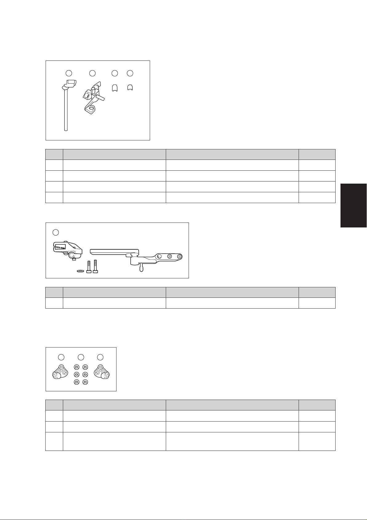
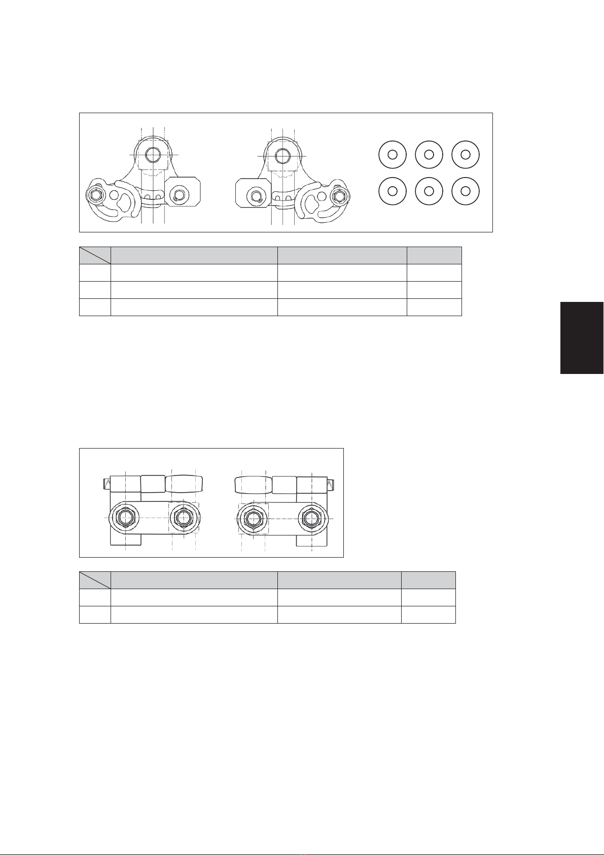
(3) Installation Brackets
Product Name Remarks Quantity
a. Bracket A for left unit 1
b. Bracket A for right unit 1
c. Width adjustment washer Used when necessary 6
* Please use a maximum of 3 washers per side.
1 Bracket A
Product Name Remarks Quantity
a. Bracket B for left unit 1
b. Bracket B for right unit 1
2 Bracket B
Use bracket B when the backward tip angle is small.
If bracket B is used, the axles of the E-Drive PLUS can be moved and installed 53.5mm back from
the back pipe of the wheelchair frame.
a. b. c.
a. b.

16
3
(4) Controller Installation
[Standard]
Product Name Remarks Quantity
1Upper holder assembly For installing the controller 1
2Under holder assembly For installing the controller 1
3Side plate for ø19–20 For installing the under holder 4
4Side plate for ø16–17 For installing the under holder 4
Product Name Remarks Quantity
1Swing out bracket For installing the controller 1
[Swing Out Bracket]
1 2 3 4
1
17
3
3.2. Power Unit Installation
3.2.1. Installation for E-Drive PLUS 20", 22", and 24" Fixed Axle Models
Required tools: 10 mm and 17 mm sockets, socket wrench, and torque
wrench
(1) Right Drive Unit Installation
(2) Left Drive Unit Installation
Install the left unit in the same way as the right unit.
(3) Angle Adjustment
To adjust the angle 30°, shift the clamp bracket slots by 1 projection on the unit.
1Install the clamp bracket for the right unit to
the E-Drive PLUS unit. Fit the projections on
the unit into the slots in the clamp bracket.
(The standard slots are Nos. 6, 7, 8, and 9.)
2While keeping the clamp bracket and right
unit in this condition, install the unit to the
wheelchair frame. Fit the back pipe of the
wheelchair frame between the post and
stopper of the clamp bracket.
3Temporarily tighten the axle using the nut
(tightening torque: approximately 5 Nm) so
that there is no looseness in the axle.
4Move the stopper so that there are no gaps
between the clamp bracket post, frame,
and stopper, and then tighten the stopper
bolt.
Tightening torque: 11 to 15 Nm
5Tighten the axle mounting nut.
Tightening torque: 40 to 50 Nm
NOTICE
When the E-Drive PLUS unit is installed, the unit and the wheelchair frame must not interfere with
each other. When installing the width adjustment washers to the shaft in order to prevent interfer-
ence, use up to 3 washers per side.

18
3
3.2.2. Installation for E-Drive PLUS 16" Fixed Axle Model (When Using Bracket A)
Required tools: 10 mm and 17 mm sockets, socket wrench, and torque
wrench
Remove the washers and O rings attached to the axle before installation.
Note
(1) Right Drive Unit Installation
(2) Left Drive Unit Installation
1Install bracket A for the right unit to the E-
Drive PLUS. Fit the projections on the unit into
the slots in bracket A.
2While keeping bracket A and the right
unit in this condition, install the unit to the
wheelchair frame. Fit the back pipe of the
wheelchair frame between stopper 1 and
stopper 2 of bracket A.
3Temporarily tighten the axle using the nut
(tightening torque: approximately 5 Nm) so
that there is no looseness in the axle.
4Move stopper 1 so that there are no gaps
between the frame, stopper 1, and stopper
2, and then tighten the stopper bolt.
Tightening torque: 9 to 11 Nm
5Tighten the axle mounting nut.
Tightening torque: 40 to 50 Nm
1Install bracket A for the left unit to the E-Drive PLUS. Fit the projections on the unit into the
slots in bracket A.
2While keeping bracket A and the left unit in this condition, install the unit to the wheel-
chair frame. Fit the back pipe of the wheelchair frame between stopper 1 and stopper
2 of bracket A.
3Temporarily tighten the axle using the nut (tightening torque: approximately 5 Nm) so
that there is no looseness in the axle.
4Move stopper 1 so that there are no gaps between the frame, stopper 1, and stopper
2, and then tighten the stopper bolt.
Tightening torque: 9 to 11 Nm
5Tighten the axle mounting nut.
Tightening torque: 40 to 50 Nm
Remove the washers and O rings
Frame pipe
Bracket A
Stopper 1
Stopper 2

19
3
(3) Angle Adjustment
1To adjust the angle 5°, turn stopper 2 on bracket A to change the contact surface of
stopper 2 and the frame.
2To adjust the angle 15°, shift the bracket A slots by 1 projection on the unit.
NOTICE
When the E-Drive PLUS unit is installed, the unit and the wheelchair frame must not interfere with
each other. When installing the width adjustment washers to the shaft in order to prevent interfer-
ence, use up to 3 washers per side.
20
3
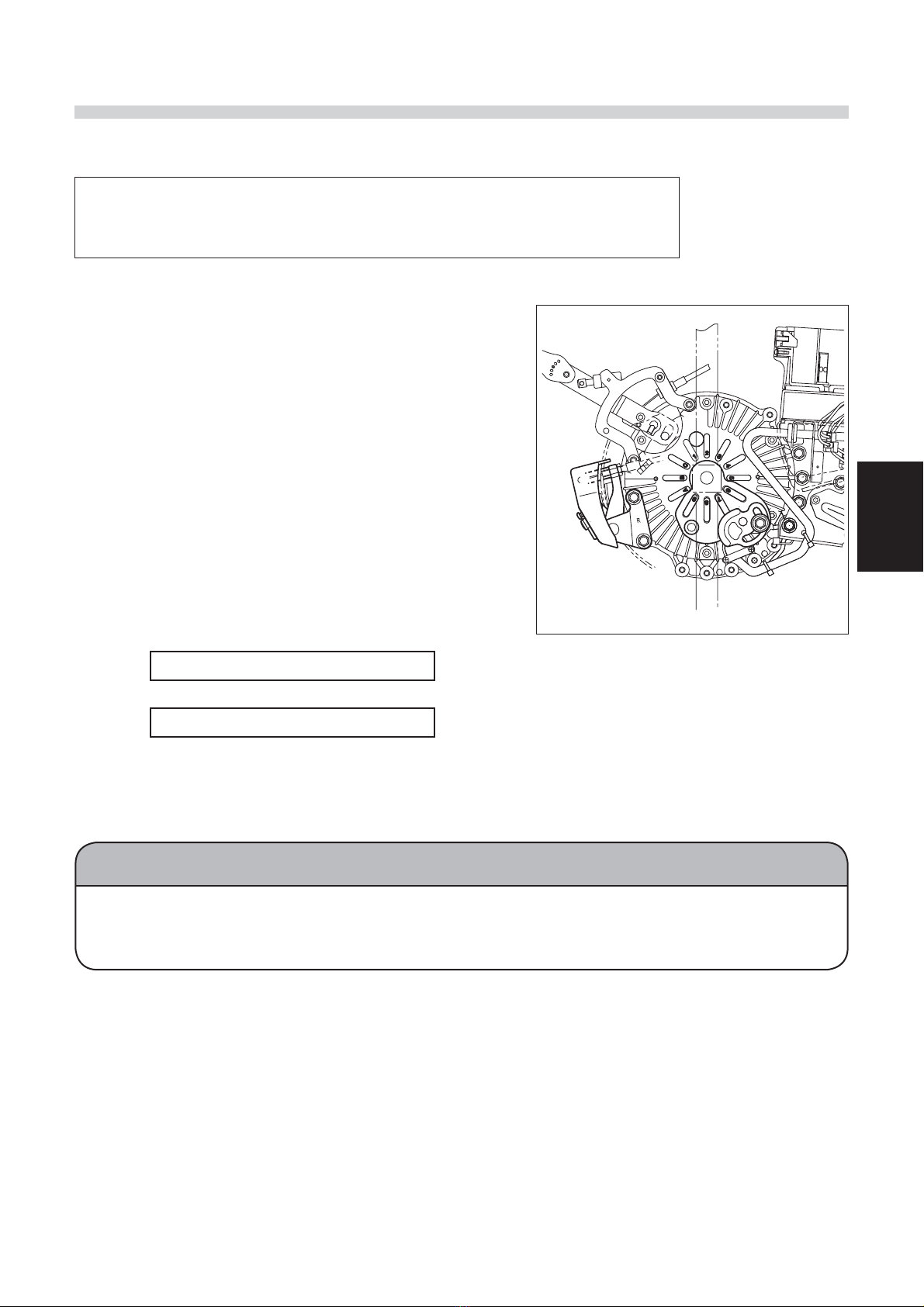
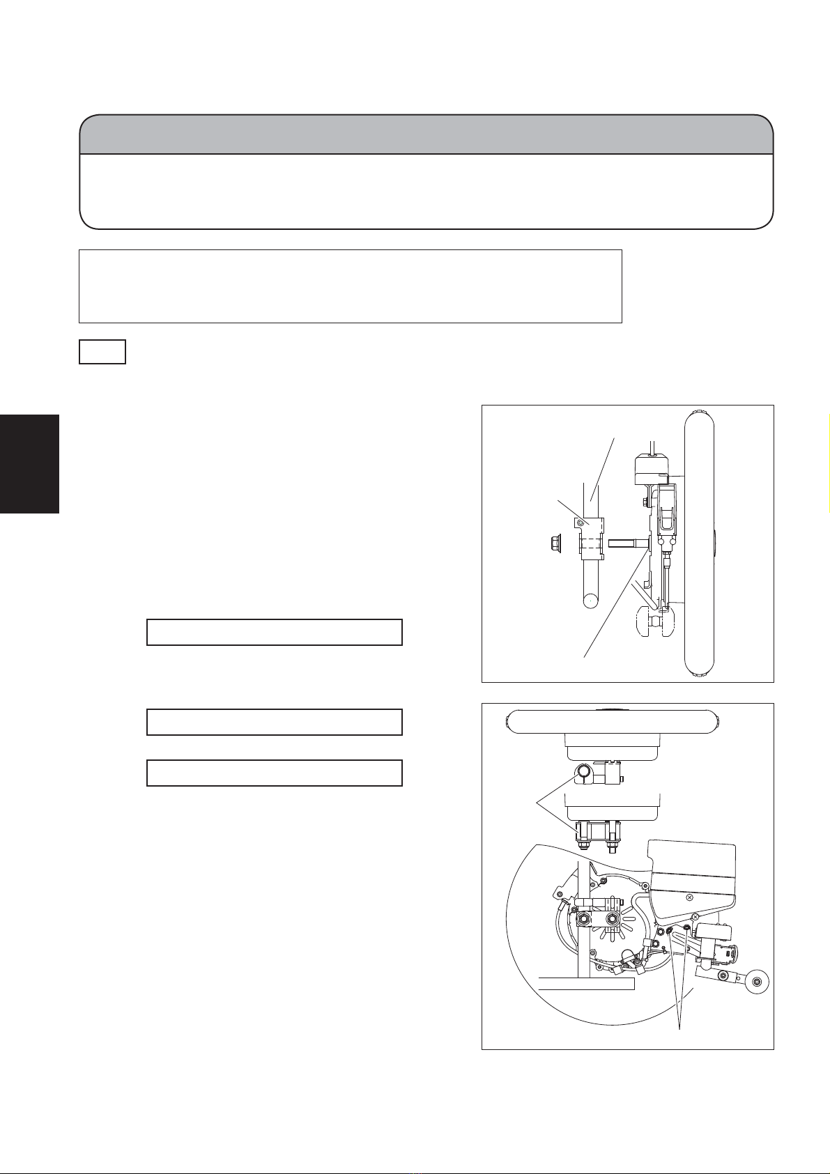
3.2.3. Installation for E-Drive PLUS 16" Fixed Axle Model (When Using Bracket B)
Required tools: 17 mm socket, socket wrench, torque wrench, 17×19
mm open-end wrench, and 5 mm hexagon wrench
Leave the washers and O rings attached to the axle during installation.
Note
(1) Right Drive Unit Installation
1Temporarily tighten bracket B for the right
unit to the back pipe using the frame axle
hole. Align the holes in the plate and boss
and tighten sufficiently to remove any
looseness.
2Temporarily tighten the drive unit using the
mounting nut. The nut is temporarily tight-
ened to prevent the drive unit from falling;
therefore, do not tighten the nut forcefully.
3Fully tighten the nut that was temporarily
tightened to the frame axle hole.
Tightening torque: 40 to 50 Nm
4Fit the projections on the back of the drive
unit into the slots in bracket B, and then
fully tighten the axle.
Tightening torque: 40 to 50 Nm
5Fully tighten the bolt.
Tightening torque: 14 to 16 Nm
NOTICE
When using bracket B to install the power unit to the wheelchair frame, be sure to
leave the O rings and washers attached to the axle. If the O rings and washers are
removed, the power unit will be damaged.
Frame pipe
Bracket B
Washer and O ring
Adjusting holes
Frame
pipe
Other manuals for E-Drive PLUS
1
Table of contents
Other decon Wheelchair manuals

decon
decon Flexlife D9 User manual

decon
decon Panthera S2/U2 User manual

decon
decon Adventus Quick start guide

decon
decon Gearwheel GWl0S0 User manual

decon
decon E-Move MEM20 User manual

decon
decon Panthera S3 Large User manual

decon
decon Gearwheel User manual

decon
decon Adventus User manual

decon
decon Infinity User manual

decon
decon INFM7002 User manual


Popular Wheelchair manuals by other brands


Amiga
Amiga TravelMate Owner operational manual

Platinum Health
Platinum Health PHB3300 Assembly and instruction manual

Evocare
Evocare LM9515 owner's manual

Merits
Merits P310 series Service manual

Special mobility
Special mobility Caddy3 user manual

Sunrise Medical
Sunrise Medical Breezy Ultra 4 Brochure & specs