Technical Specifications and Operating Procedure. PILATUS3 S 6M-NSRRC Detector System. Version: V1.0 5/33
List of Figures
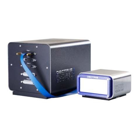
Figure 1: Rendering of the PILATUS3 S 6M-NSRRC detector consisting of detector head (left, with
the front side facing down and the back side facing up) and detector electronics (right).................13
Figure 2: Drawing of the PILATUS3 S 6M-NSRRC detector head (printed separately in the user
documentation folder). ......................................................................................................................13
Figure 3: Drawing of the PILATUS3 S 6M-NSRRC detector electronics (printed separately in the
user documentation folder). ..............................................................................................................14
Figure 4: The PILATUS3 S 6M-NSRRC detector head with the blank flange in place (left).......................15
Figure 5: The PILATUS3 S 6M-NSRRC detector head viewed from the back (left) and its connection
layout (right). .....................................................................................................................................15
Figure 6: PILATUS3 S 6M-NSRRC detector electronics viewed from the front (left) and its
connection layout (right)....................................................................................................................16
Figure 7: The PILATUS3 S 6M-NSRRC detector electronics viewed from the back..................................16
Figure 8: Configuration of the PILATUS3 S 6M-NSRRC detector system. ................................................18
Figure 9: Drawing of the PILATUS3 S 6M-NSRRC detector base plate (printed separately in the user
documentation folder). ......................................................................................................................21
Figure 10: Mounting from below, bottom view. ...........................................................................................22
Figure 11: Error message when temperature or humidity is out of range...................................................25
Figure 12: Correct start-up message...........................................................................................................25
List of Tables
Table 1: Document history. ...........................................................................................................................6
Table 2: List of changes................................................................................................................................6
Table 3: Safety symbols................................................................................................................................7
Table 4: Technical specifications. ...............................................................................................................10
Table 5: Ratings. .........................................................................................................................................11
Table 6: Detector operating conditions. ......................................................................................................12
Table 7: Vacuum field codes.......................................................................................................................12
Table 8: The meaning of the status LEDs on the detector back plane.......................................................17
Table 9: Connectors and connecting cables/pipes. ....................................................................................18
Table 10: Temperature and humidity limits.................................................................................................24
Table 11: Troubleshooting...........................................................................................................................32


