DediProg SF600 User manual

SF600/SF600
Plus
Serial Flash Programming solution
www.dediprog.com 1
SF600/SF600Plus
Serial Flash Programming solutions
The Innovative solution to update the Serial Flash on board and Offline
High performances
USB High speed support
In Circuit Programming (program on board SPI Flash)
Socket Programming (program SPI flash in the socket)
Start Button function
Standalone mode (SF600Plus): Update the Serial flash without computer
Support single, Dual and Quad IO
Three software optimized interfaces:
-
Engineering Interface for expert
-
Command Line for automatic control
-
Production interface for operator
Multi-Programmers support through USB
Friendly and powerful tool with free life time update via Website
Portable programmer
Advanced I/O control

SF600/SF600
Plus
Serial Flash Programming solution
www.dediprog.com 2
I. Products comparison.................................................................3
II. SF600 and SF600Plus description ...............................................4
2.1 Interface description .............................................................................4
2.2 ICP Header description .......................................................................... 6
2.3 Application Header................................................................................ 8
2.3.1 Backward compatibility with SF100 ................................................................... 8
2.3.2 Application Universal Header............................................................................. 8
2.3.3 Pin Header pitch ................................................................................................. 8
III. Programming methods ..............................................................9
3.1 In Circuit Programming..........................................................................9
3.2 SPI bus in High Impedance .................................................................... 9
3.3 SPI bus isolation circuit.......................................................................... 9
3.4 Backup Boot Flash method.................................................................. 10
3.5 Socket Programming ........................................................................... 11
IV. SF600 and SF600Plus software.................................................13
4.1 USB mode ............................................................................................ 13
4.1.1 Engineering User Interface ............................................................................... 13
4.1.2 Command line Interface ................................................................................... 14
4.1.3 Production User interface ................................................................................ 15
4.2 Standalone mode (SF600Plus) ............................................................. 16
4.2.1 Project Preparation........................................................................................... 16
4.2.2 Standalone programming ................................................................................. 16
V. Specification............................................................................17
5.1 USB Connector..................................................................................... 17
5.2 DC and IO characteristics..................................................................... 17
5.2.1 Socket DC Characteristics ................................................................................. 17
5.2.2 ICP DC and AC characteristics........................................................................... 17
5.2.3 ICP timing.......................................................................................................... 20
5.2.4 Host PC requirements....................................................................................... 21
VI. Programming Performance......................................................22
VII.Revision History ......................................................................23
Important notice:
This document is provided as a guide line and must not be disclosed without consent of
DediProg. However, no responsibility is assumed for errors that might appear.
DediProg reserves the right to make any changes to the product and/or the specification at
any time without notice. No part of this document may be copied or reproduced in any
form or by any means without prior written consent of DediProg.
SF600/SF600
Plus
Serial Flash Programming solution
www.dediprog.com 3
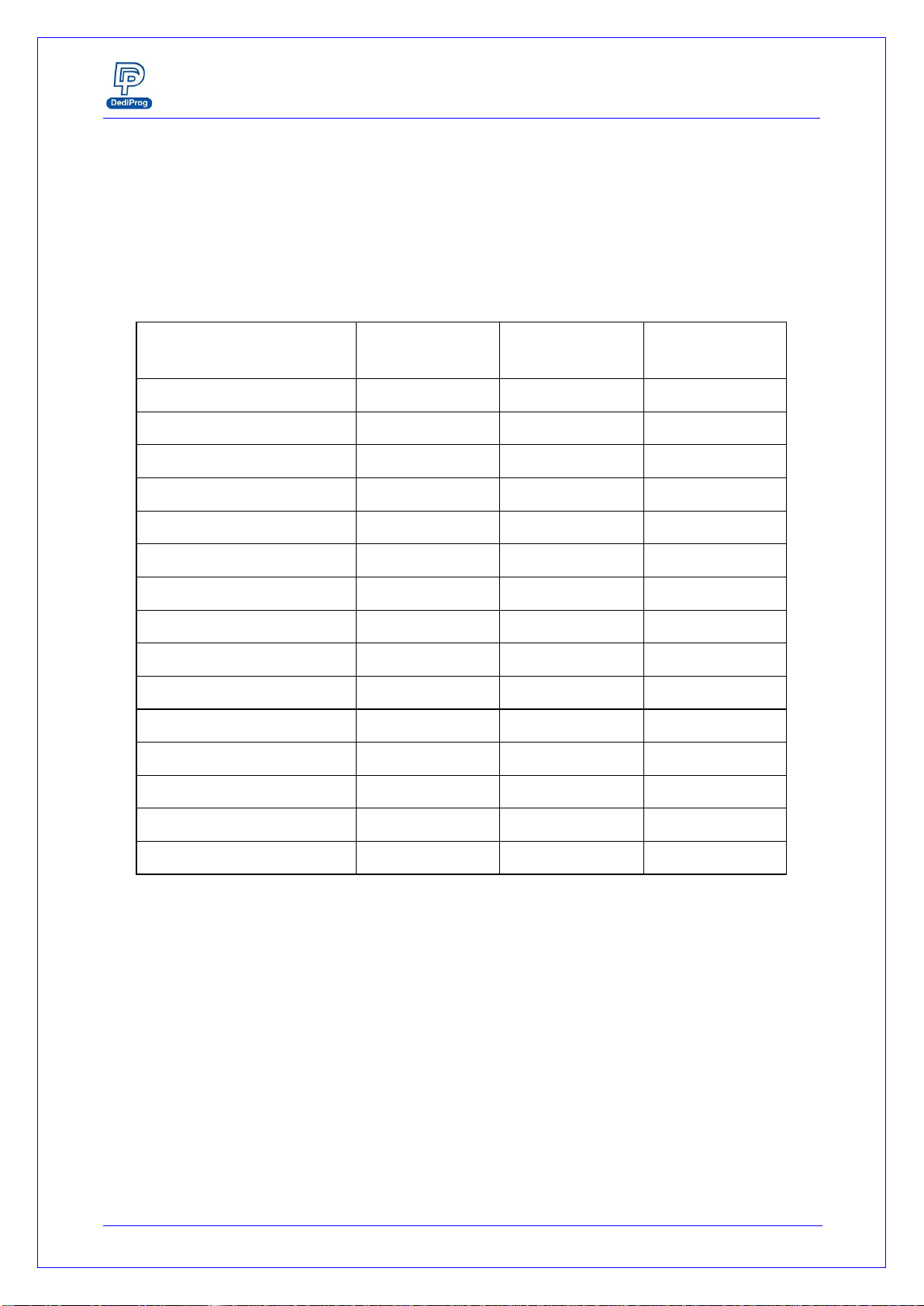
I. Products comparison
The Universal Programmers available on the market are not optimized for the Serial Flash
and offer low performances for high price. DediProg team has therefore developed the
optimum solutions to cover all our customers’ needs.
Table1: Comparison table
Features
SF100
SF600
SF600Plus
Support all Serial Flash
V
V
V
USB 2.0 Full speed
V
USB 2.0 High speed
V
V
In Circuit Programming
V
V
V
Socket programming
V
V
Standalone mode
V
Start Button feature
V
V
Multi-Programmers USB
V
V
V
Engineering GUI
V
V
V
Command Line
V
V
V
Production GUI
V
V
V
Backup Boot Flash
V
V
V
Single IO
V
V
V
Dual IO
V
V
Quad IO(ICP mode only)
V
V
NEW

SF600/SF600
Plus
Serial Flash Programming solution
www.dediprog.com 4
II. SF600 and SF600Plus description
SF600 and SF600Plus have been designed to offer the best possible performances to
program the SPI Flash in different conditions.
2.1 Interface description
Fig 1: SF600/SF600Plus Programmer
A. USB Connector
USB connector is used to communicate with the SF software during the USB mode or to
provide the power during the standalone mode.
B. Power Connector
Connect power adaptor to SF600/SF600Plus when executing standalone programming.
C. Power LED
Power LED shines when SF600/SF600Plus is powered by USB or power adaptor.
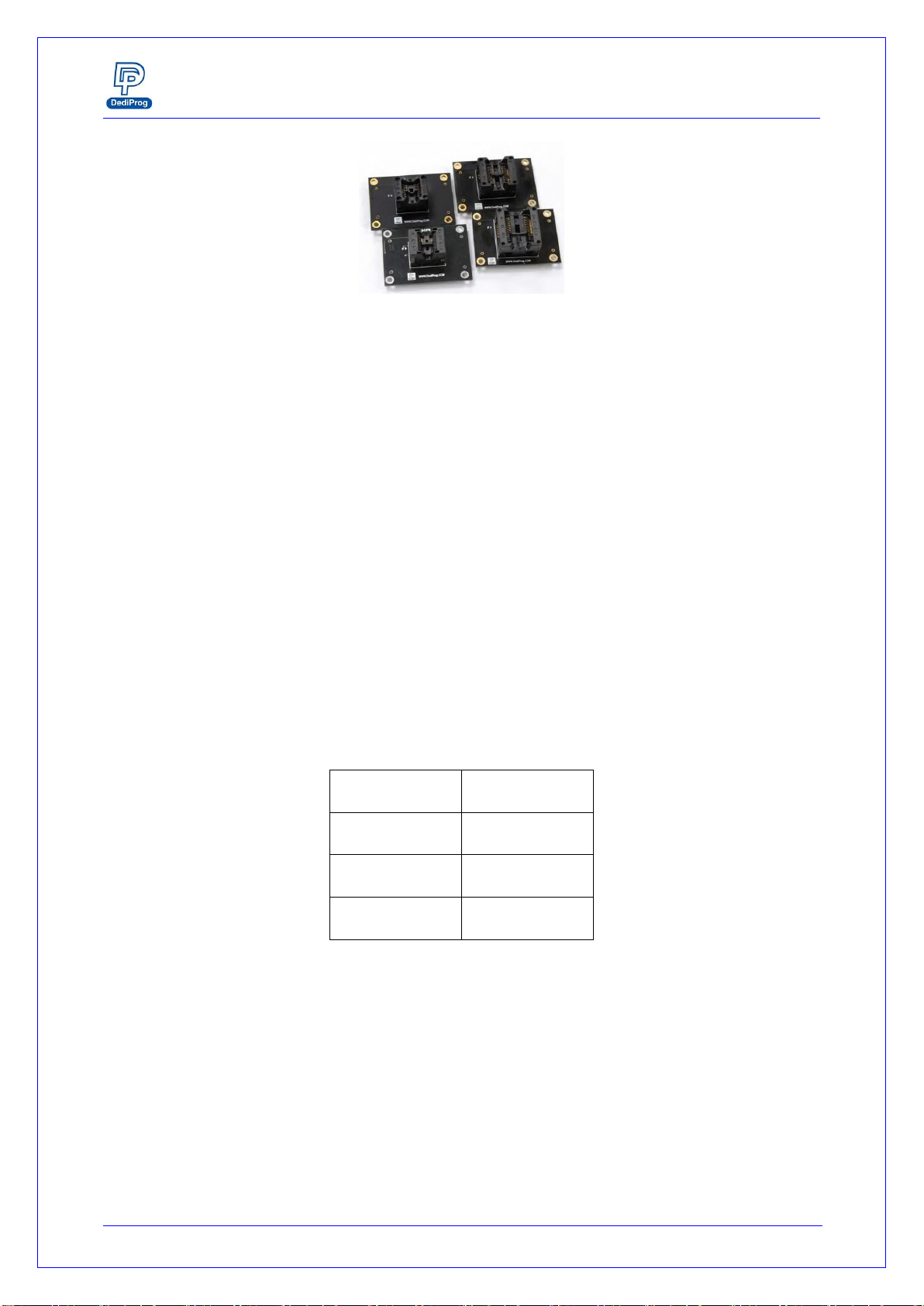
D.Socket Adaptor Headers
Plug the DediProg socket adaptors and program the Serial flash off line. DediProg is
providing different socket adaptors to fit the market SPI Flash packages. Review the
socket adaptor available on DediProg website.
H. Start Button
F. Operation LED
A. USB Connector
B. Power Connector
C. Power LED
D. Socket Adaptor
Headers
E. ICP Connector
G.Com Port
SF600/SF600
Plus
Serial Flash Programming solution
www.dediprog.com 5
Fig 2: Socket adaptors
E. ICP Connector
ICP connector is used to connect ICP cable when executing ICP programming.
F. Operation LED
Red Led: error
Orange Led: operation on going
Green Led: pass
G.Com Port
The Com Port design is for integrating SF600/SF600Plus with customer's system. All
programmer pin outs (except 5V and NC) are default with Low status. Once
customer/system sends a High signal to trigger START which needs press and hold one
second and make the programmer working (i.e. BUSY becomes High status accordingly),
SF600/SF600Plus will also feedback PASS or FAIL result with High signal after
programming.
NOTE:
The input voltage range is between 3.5V to 6.5V which means High. The voltage cannot
over 6.5V that may cause the component damage.
Table 2: Pin Out
1
GND
2
NC
3
5V
4
START
5
FAIL
6
PASS
7
BUSY
8
NC
H.Start Button
The Start button is operations from the programmer either in USB mode. By pressing
and hold 2 seconds the start button, the SF600 and SF600Plus starts to execute the
operation procedures defined in the software Batch configuration when working in USB
mode or in the project pre-loaded to the SF600Plus when working in standalone mode.
SF600/SF600
Plus
Serial Flash Programming solution
www.dediprog.com 6
2.2 ICP Header description
The In Circuit Programming Header and cable are used to program the on board Serial
Flash. The flat cable is flexible and convenient to manipulate. It must be kept as short as
possible to not impact the signal quality. Even if SF600 and SF600Plus strong buffers can
drive high capacitance, the communication failure can occur due to weaker driving
capability of the on board Serial Flash. In case of communication problems, try to reduce
the bus frequency from the software interface.
For customization of the ICP-cable (number of signals, pin out assignment or connector
size), please contact DediProg. DediProg is providing additional accessories to fit your
target board like:
A. ICP split cable:
You can connect each signal individually according to your own pins assignment.
B. SO Test Clip:
You can connect the SF600/SF600Plus directly on the Serial flash SO package (SO8N,
SO8W, and SO16W)
Table 3: SF600 and SF600Plus Pin Header description:
1
Vpp
CS2
2
3
CS1
Vcc
4
5
MISO/DQ1
Hold/DQ3
6
7
Wp/DQ2
CLK
8
9
GND
MOSI/DQ0
10
11
NC
Reset/IO3
12
13
NC
NC
14
15
NC
NC
16
17
NC
NC
18
19
GPIO1
GPIO2
20

SF600/SF600
Plus
Serial Flash Programming solution
www.dediprog.com 7
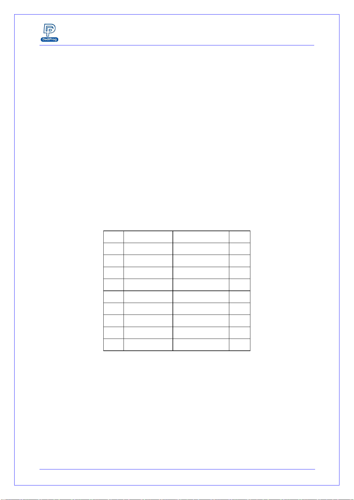
Table 4: Description of the signals:
Pin
Number
Name of the
signals
Description
1
Vpp
High voltage applied on the SPI Flash to speed up the
programming and erasing operations.
2, 3
CS1, CS2
Chip select of two Serial Flashes. Serial Flash 1 or 2 can be
selected from the software.
4
Vcc
Vcc is used to supply the application SPI Flash. The Vcc level
can be adjusted from the software. A diode protects the
SF600/SF600Plus Vcc from the application Vcc.
5
MISO/DQ1
Data out from the application memory (master in slave out)
when memory work in single IO mode. Bi-directional when
memory works in Dual or Quad IO mode.
6
Hold/DQ3
Driven High when Hold function is active. Bi-directional when
memory works in Quad IO mode.
7
Wp/DQ2
Driven High when Wp function is active. Bi-directional when
memory works in Quad IO mode.
8
CLK
SPI clock signal
9
GND
GND is the common ground shared between application and
programmer
10
MOSI/DQ0
Data in of the application SPI Flash (master out slave in)
when memory work in single IO mode. Bi-directional
when memory works in Dual or Quad IO mode.
12
Reset/IO3
Open drain output driven low prior any SF600/SF600Plus
operation. Reset/IO3 can be used to turn on the application
isolation circuit or reset the target system in order to drive the
Serial bus in High Impedance.
11, 13,
14, 15,
16, 17,
18
NC
Not connected
19, 20
General purpose
I/O
General I/O can be used for customization.

SF600/SF600
Plus
Serial Flash Programming solution
www.dediprog.com 8
2.3 Application Header
2.3.1 Backward compatibility with SF100
The SF600 and SF600Plus pin header assignment has been changed versus the SF100 in
order to support the new Serial Flash features like Quad IO and to be compatible with
others DediProg development tools like EM100pro SPI Flash emulator and Backup Boot
Flash tools. If your application has been designed for the SF100, DediProg is providing
with the SF600 and SF600Plus an adaptor to be backward compatible.
2.3.2 Application Universal Header
For new application design, DediProg strongly recommend to implement the universal
Header so you can benefit of all the development tools available and future features of
the Serial Flash and controllers.
-One or two Serial Flash programming
-Single, dual and Quad IO programming
-Controller Reset mode
Table 5: Universal Pin Header for application design
1
Vpp
CS2
2
3
CS1
Vcc
4
5
MISO/DQ1
Hold/DQ3
6
7
Wp/DQ2
CLK
8
9
GND
MOSI/DQ0
10
11
NC
Reset
12
*NC: Not connected
It is recommended to keep the Header 2*6 even if some signals are unused (Vpp, CS2,
Hold, Wp, reset). The header will stay compatible with the female connector supplied
by default with the SF600 and SF600Plus.
Pin 11 can be used as insertion mistake proof pin. To support this protection of wrong
insertion, the pin 11 has to be cut in the application and the corresponding hole of the
cable connector must be filled accordingly.
2.3.3 Pin Header pitch
The default cable and female connector provided with SF600 and SF600Plus is a
2.54mm pitch.
For space saving reason, you may decide to implement a 1.27mm pitch connector on
your application board. DediProg proposes an adaptor board to convert from 2.54mm
to 1.27mm.
SF600/SF600
Plus
Serial Flash Programming solution
www.dediprog.com 9
III. Programming methods
3.1 In Circuit Programming
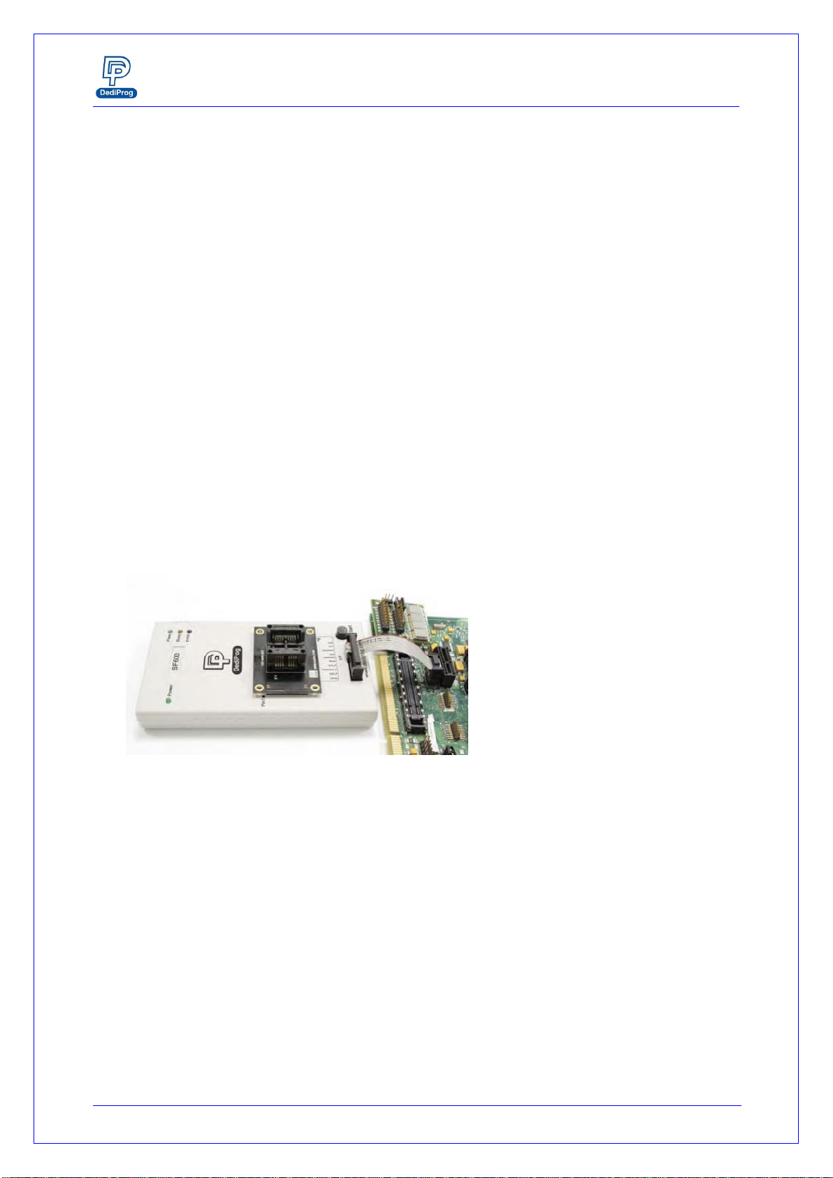
The SF600 and SF600Plus programmers have been designed to meet the strong and
growing demand of serial flash users to program and update the memories soldered on
board during development, production, and field manipulation or repairing with high
performance and low cost.
Important:
Socket adaptor and In Circuit Programming cannot be used in the same time. To use the
In Circuit programming, the socket adaptor has to be removed.
SF600 and SF600Plus can support dual and quad IO programming offering the shortest
programming time even if the application board total capacitance do not permit high
frequency.
Before trying to update the Serial Flash soldered on Board, make sure that the SPI
controller and the application are compatible with the In Circuit Programming method to
avoid any conflict with the programmer.
Fig 3: SF600/SF600Plus connected to the application header
3.2 SPI bus in High Impedance
The SF600/SF600Plus reset signal can be used to reset the target board and switch the
application controller in reset mode. User must check if the SPI bus is released in high
impedance during this mode to prevent any conflict between the programmer and the
application controller. In this mode, the on board flash is supplied by the application.
3.3 SPI bus isolation circuit
If the application controller does not release the SPI bus in high impedance during reset
then an isolation circuit (MOSFET, switch, multiplexer...) must be designed in order to
isolate the programmer and serial flash from the application controller during the
update.

SF600/SF600
Plus
Serial Flash Programming solution
www.dediprog.com 10
DediProg has published an Application Note and reference schematic to help designers to
implement the In Circuit Programming method and will be pleased to answer any of your
questions on this subject.
Code programming or Update flexibility:
-For code trials during Research and Development (R&D)
-For Production programming
-For application code update or customization in warehouse
-For repairing or update in the field
3.4 Backup Boot Flash method
SF600 / SF600Plus can also be used together with DediProg backup boot flash modules so
that it forces the application to boot from the backup flash located in the backup boot
flash module instead of the soldered SPI flash on the application which it is disabled. The
backup serial flash can then be accessed at any time by the SF600 / SF600Plus without
any possible conflict with the application controller. In this case, SF600 / SF600Plus
cannot update directly the on board Serial Flash to avoid conflict with the controller.
Applications:
A. Development purpose as the system can boot from the backup Flash for the code
trials. Engineer can update safely the backup Flash with new code and without any
conflict risk with the application controller.
B. Repair purpose as the system can still boot from a backup memory even if the on
board Serial flash is corrupted. The technician can use the application flash update
tools after the boot to update the on board Serial flash.
Remark: Pin header adapter need to be used
Fig 4: Backup Boot Flash (BBF) connected to SF600 and SF600Plus
Backup memory

SF600/SF600
Plus
Serial Flash Programming solution
www.dediprog.com 11
3.5 Socket Programming
The SF600 and SF600Plus have been designed to support the DediProg socket adaptors
and offer the socket programming flexibility. Different sockets adaptor are provided to fit
the different Serial Flash packages proposed in the market. Please note that socket mode
only supported Single and Dual IO.
A. For development:
Socket programming can be used during development when an engineering socket is
soldered in the target application board so that Serial Flash can be manually removed
and programmed in the SF600 and SF600Plus socket. DediProg supplies engineering
sockets which are footprint compatible with the SPI Flash.
B. For Production:
Socket programming can be used to program the Serial Flash before soldering.
DediProg software supports multi-programmers through USB to program few serial
Flash in parallel and SF600 and SF600Plus also supports Standalone mode.
Fig 5: SF600/SF600Plus with Socket adaptor
Important:
Socket adaptor and In Circuit Programming cannot be used in the same time. To use the
socket programming, the in Circuit Programming cable has to be unconnected.

SF600/SF600
Plus
Serial Flash Programming solution
www.dediprog.com 12
Note:
The new socket adaptor has a white triangle marker on the left and lower side of the
socket. Shown as below
To avoid plugging the wrong direction to the socket header, please ensure the marker
to aim at the Pin 1 position.

SF600/SF600
Plus
Serial Flash Programming solution
www.dediprog.com 13
IV. SF600 and SF600Plus software
4.1 USB mode
In USB mode, user can control the programmer operations via a friendly interface. He can
load a file, blank check, program and verify the target Serial Flash. Batch button provides
an easy way to perform more than one operation in one click.
User can also edit the buffer, files and SPI Flash content and compare.
DediProg provides three different users interface to fit better our customers’ needs. For
more information on the SF600 and SF600Plus software, please refer to the user manual.
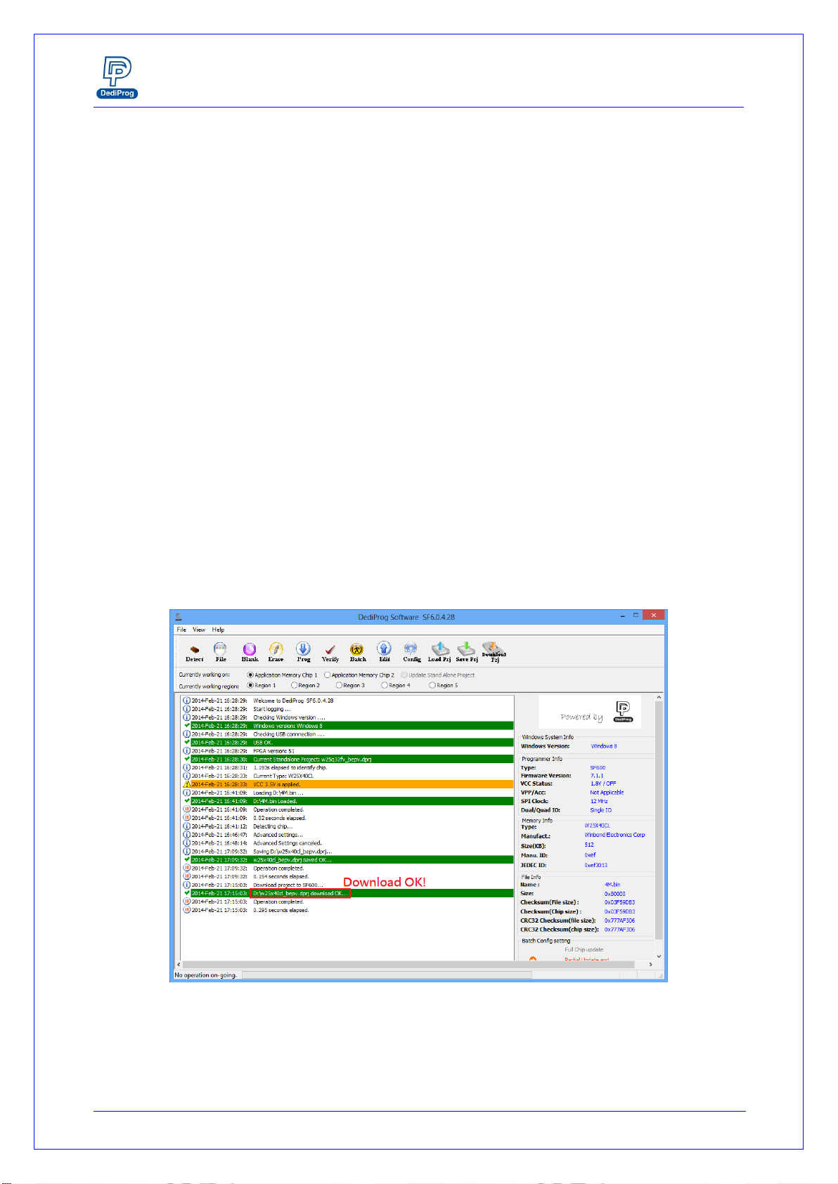
4.1.1 Engineering User Interface
The engineering user interface has been designed to offer the expert features for
engineers during development. Please note the “Download Prj”button is only for
SF600Plus. The details for the download project feature are descripted in DediProg
user manual.
Fig 6: SF600 Engineering GUI

SF600/SF600
Plus
Serial Flash Programming solution
www.dediprog.com 14
Fig 7: SF600Plus Engineering GUI.
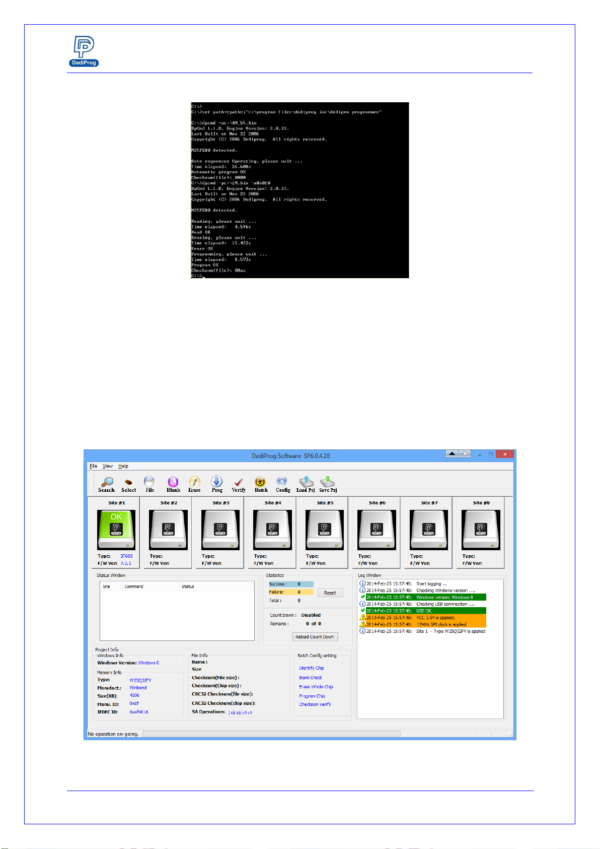
4.1.2 Command line Interface
The command line interface has been designed to offer a faster user control of the
programmer or an automatic control of the programmer from other software.
Faster control:
User can quickly perform some repetitive operations just by typing the command on
our Window DOS interface.
Automatic control:
The command line can be called by other software to take the control over the
programmer.
Benefits:
-SF600 and SF600Plus can be controlled by the compiler in order to automatically
program the Serial Flash with the new code for trials
-SF600 and SF600Plus can be integrated in your production line and be controlled
by the In Circuit Tester to program the on board serial flash after the testing
has been successfully performed.
SF600/SF600
Plus
Serial Flash Programming solution
www.dediprog.com 15
Fig 8: Window DOS interface
4.1.3 Production User interface
The production user interface has been designed to offer the optimum interface to
control volume programming:
-Simple interface to fit to the operator needs
-Project loading to reduce the human errors
-Monitor multiple programmers operation in one window
-Control your ongoing project performances (counters, failure rate...etc.)
Fig 9: Production GUI
SF600/SF600
Plus
Serial Flash Programming solution
www.dediprog.com 16
4.2 Standalone mode (SF600Plus)
The SF600Plus has been designed to work in standalone mode that is optimized for
production as each programmer does not require to be connected to the computer.
Before to work in standalone mode, user needs to download the existed project from
PC to SF600Plus embedded memory.
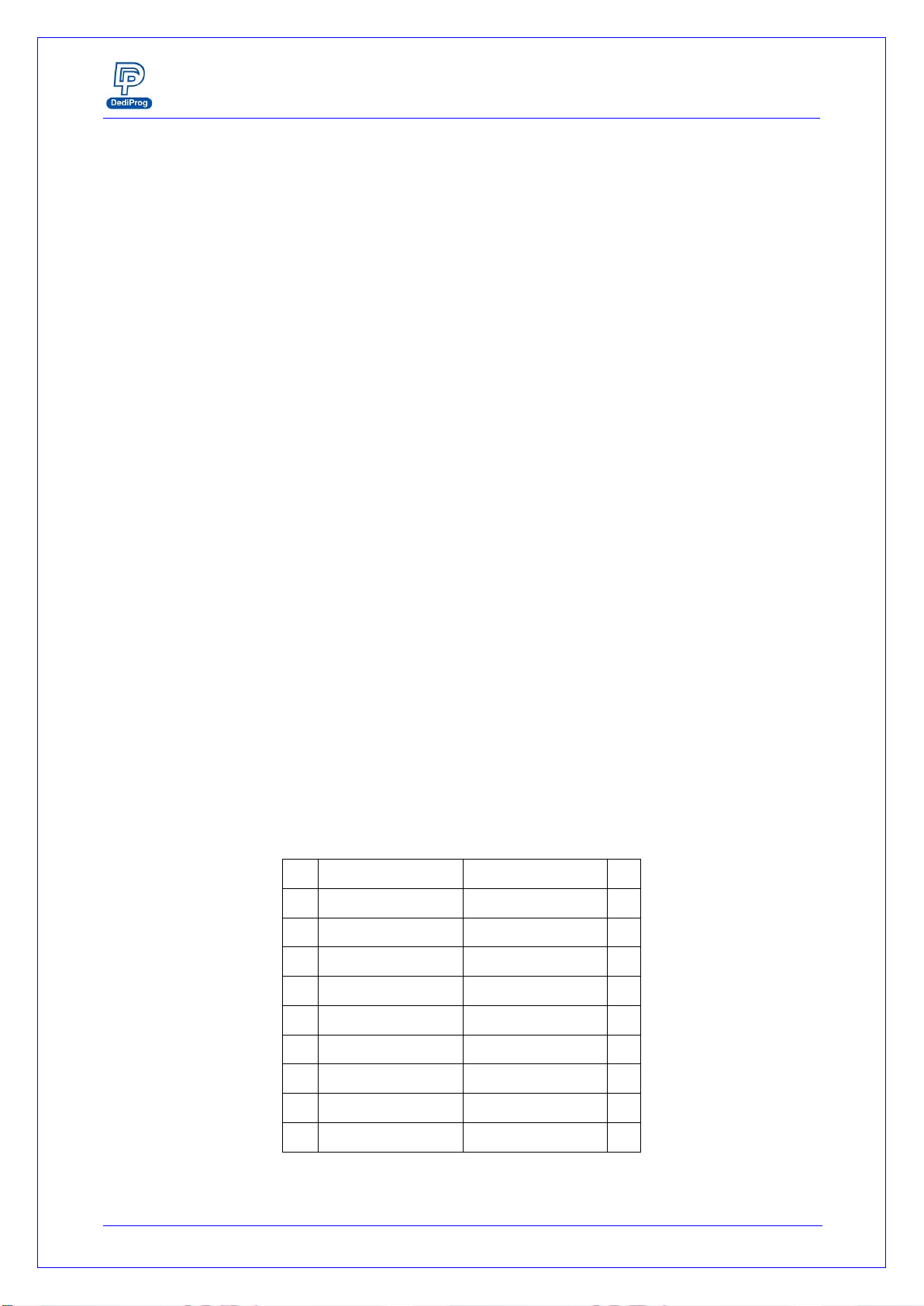
4.2.1 Project Preparation
In order to perform standalone programming, the contents and the programming
operation procedures have to be pre-downloaded to the SF600Plus embedded
memory through the USB with the software provided by DediProg.
Prepare a standalone programming project
A. Open DediProg Production Software.
B. Select IC brand and part number.
C. Load the programing file.
D. Click “Config” Icon to set programming flow.
E. Save dprj file to PC.
F. Click “Download Prj”to download project to SF600Plus embedded memory
G. Download project successful
Fig 10: SF600Plus download project successful interface
4.2.2 Standalone programming
When the project is available in the SF600Plus embedded memory, the user can run the
project from push the start button.
SF600/SF600
Plus
Serial Flash Programming solution
www.dediprog.com 17
V.Specification
5.1 USB Connector
The USB connector type A is available to communicate with the computer tool or to
supply the programmer in Standalone mode. When in Standalone mode, the SF600Plus
has to be supplied through the USB connector or the 5V power jack. This could be
achieved by:
-Connecting the SF600Plus to a computer for the USB power
-Connecting the SF600Plus to a standard USB Hub (500mA min)
-Connecting the SF600Plus to the 5V/1A power adaptor through the power jack
USB Power supply specification:
-Vdd = 5V ± 5%
-Idd min = 500mA
5.2 DC and IO characteristics
5.2.1 Socket DC Characteristics
User can adjust the power supply of the target Serial Flash from the software interface.
The Vcc can be set from 1.8V to 3.8V.
The SPI signals levels are generated according to the Vcc selected.
5.2.2 ICP DC and AC characteristics
The ICP connector is a 10x2 pin header straight type with 2.54mm pitch. It is used to
control the application SPI Flash, and if necessary supply the SPI Flash, provide the high
voltage to the SPI Flash, or reset the application chipset, etc.
Table 6: SF600 and SF600Plus Pin Header description:
1
Vpp
CS2
2
3
CS1
Vcc
4
5
MISO/DQ1
Hold/DQ3
6
7
Wp/DQ2
CKL
8
9
GND
MOSI/DQ0
10
11
NC
Reset/IO3
12
13
NC
NC
14
15
NC
NC
16
17
NC
NC
18
19
GPIO1
GPIO2
20
SF600/SF600
Plus
Serial Flash Programming solution
www.dediprog.com 18
A. Application SPI Flash supply: Vcc
Specification for the ICP Vcc pin:
-Vcc is set at 3.3V by default and can be adjusted down to 1.8V from the
software interface
-Icc max supplied = 100mA
The application SPI Flash can be supplied by two different sources:
a) by the programmer via ICP Vcc pin at 3.3V
b) by the application according to the SPI Flash specification
The SF600 and SF600Plus have been designed with a Serial diode on the Vcc to
protect against any conflict with the application Vcc.
B. SPI signals management: CS1, CS2, CLK, MISO, MOSI, DQ0-4, IO, reset/IO3
The SPI signals are used to communicate with the application SPI Flash with a high
frequency (up to 25MHZ). The frequency can be also adjusted from the software
interface. The signals are CMOS compatible and are switched in High Impedance
when not used. The SPI signals are turned in Low impedance after reset has been
driven low.
Table 7: DC specification for SPI signals and IO
Symbol
Parameter
Test condition
Value
Unit
Vcc(V)
Io(mA)
Vih
High Level Input
Voltage
2.7V to 3.6V
2V
V min
2.3V to 2.7V
1.7V
V min
1.65V to 1.95V
0.65XVcc
V min
Vil
Low Level Input
Voltage
2.7V to 3.6V
0.8V
V max
2.3V to 2.7V
0.7V
1.65V to 1.95V
0.35XVcc
Ioh
High Level Output
current
3V
-24mA
mA
2.7V
-12mA
mA
2.3V
-12mA
mA
1.65V
-4mA
mA
Iol
Low Level Output
current
3V
24mA
mA
2.7V
12mA
mA
2.3V
12mA
mA
1.65V
4mA
mA
Cap
Capacitance
10nF
nF typ
This specification is relative to individual capability of one signal.
ESD high performance protection compliant with IEC61000-4-2 level 4: 15kV
(air discharge)
8kV (contact discharge)

SF600/SF600
Plus
Serial Flash Programming solution
www.dediprog.com 19
Remark: the total capacitance added on the application SPI bus will also depend on the
ICP cable length. The ICP cable length must be reduced at the minimum. The SPI flash
output buffer capability (MISO) is limited compared to the programmer performances.
So even if the programmer is able to drive high capacitance, the Serial Flash soldered
on the application will probably not (information read from SPI Flash will be wrong).
C. Smart management of the SPI Flash Vcc and SPI signals
In order to minimize the impact of the ICP method on the chipset and application
board, the programmer supplies the application Serial Flash with Vcc and SPI signals
only during the programmer and Serial Flash operations.
Advantages:
a) The programmer is plugged on the application board with Vcc OFF and SPI
signals in High Impedance to avoid inrush current.
b) All the ICP pins are protected with ESD high performance protections to
discharge the Electronics charge before the connection and protect the
application.
c) The Serial Flash Vcc and SPI signals are provided only when the user send the
command and are switched OFF automatically when the operation is completed.
Therefore, the programmer is transparent for the application and can be kept
connected during application trials.
D. High voltage supply: Vpp/Acc
Specification for the Vpp pin
Vpp = 5V to 12V
Ipp max = 70mA
The Vpp high voltage can be supplied by the programmer and used to speed up
programming and erasing of the application Serial Flash if this feature is supported
by the Serial Flash supplier.
The Vpp supply will be applied automatically by the programmer on the Vpp pin
only during erase, write, or programming operations and only if the Vpp option has
been enabled on the software. The programmer will also control the Vpp voltage
level according to the Serial Flash connected and its specification.
E. I/O management: IO1, IO2, Reset/IO3
Two general IO are available on the ICP connector and one Reset for custom
needs. The IOs and reset are in High Impedance (HZ) state if there is no software
operation ongoing.
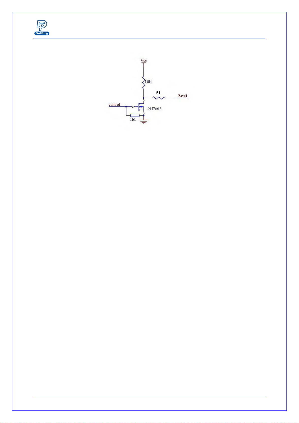
Reset/IO3: The reset/IO3 pin is an open drain output which can be used to reset
the target system or turn off the isolation circuit.
SF600/SF600
Plus
Serial Flash Programming solution
www.dediprog.com 20
Fig 11: Circuit diagram:
IO: The IO signals are in input mode by default. Behavior to be customized.
For the DC characteristics of IO1 and IO2 please refer to the DC table.
ESD high performance protection compliant with IEC61000-4-2 level 4: 15kV
(air discharge) 8kV( contact discharge)
5.2.3 ICP timing
The IO and reset have been designed to set the application in programming mode
before applying the SPI signal. They can be used to reset the target application, to turn
OFF MOSFET and isolate the SPI bus when programmer is working.
A. If No programmer operation is on going
All our SF600 and SF600Plus outputs are equivalent to high impedance.
B. When an operation is requested on the user interface
-IO1, IO2 are kept in Input by default (High Impedance)
-Reset/IO3 signals are driven Low.
C. 3 ms after Reset is switched to Low Impedance, the SPI outputs are switched in
low impedance too.
-CS1 and CS2 are driven high
-Clock and MOSI are driven low
-DQ0-3 are driven low if Quad IO outputs is enable
-Hold, Wp are driven High if single IO mode is used
D. The programmer is then ready for the communication with the Serial Flash.
So designer can use the Reset signal to reset or switch the application Serial bus in
High impedance. Application controller or circuitry will have a delay of 3ms
between Reset is driven low and Programmer SPI outputs are switched from High
Impedance to Low Impedance. SPI communication starts 6ms after reset has been
driven low.
Other manuals for SF600
1
This manual suits for next models
1
Table of contents
Other DediProg Motherboard manuals

DediProg
DediProg NuProg-E User manual

DediProg
DediProg StarProg-A User manual

DediProg
DediProg NuProg-E User manual

DediProg
DediProg NuProg-E2 User manual

DediProg
DediProg NuProgPlus-U8 User manual

DediProg
DediProg SF600 Instruction Manual

DediProg
DediProg StarProg-ATE User manual

DediProg
DediProg StarProg-ATE User manual

DediProg
DediProg StarProg Series User manual

DediProg
DediProg NuProg-F8 User manual


