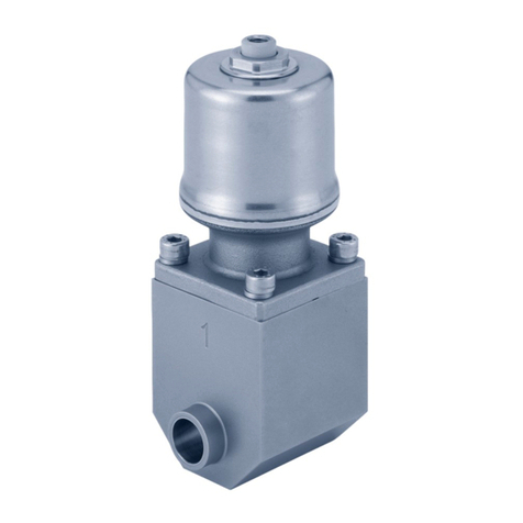
Definox ICS Operation and maintenance manual


Other manuals for ICS
1
Table of contents
Other Definox Control Unit manuals
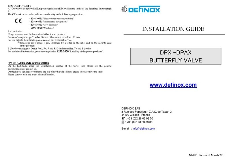
Definox
Definox DPAX User manual
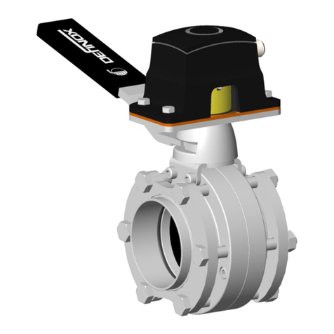
Definox
Definox DPX EBC User manual
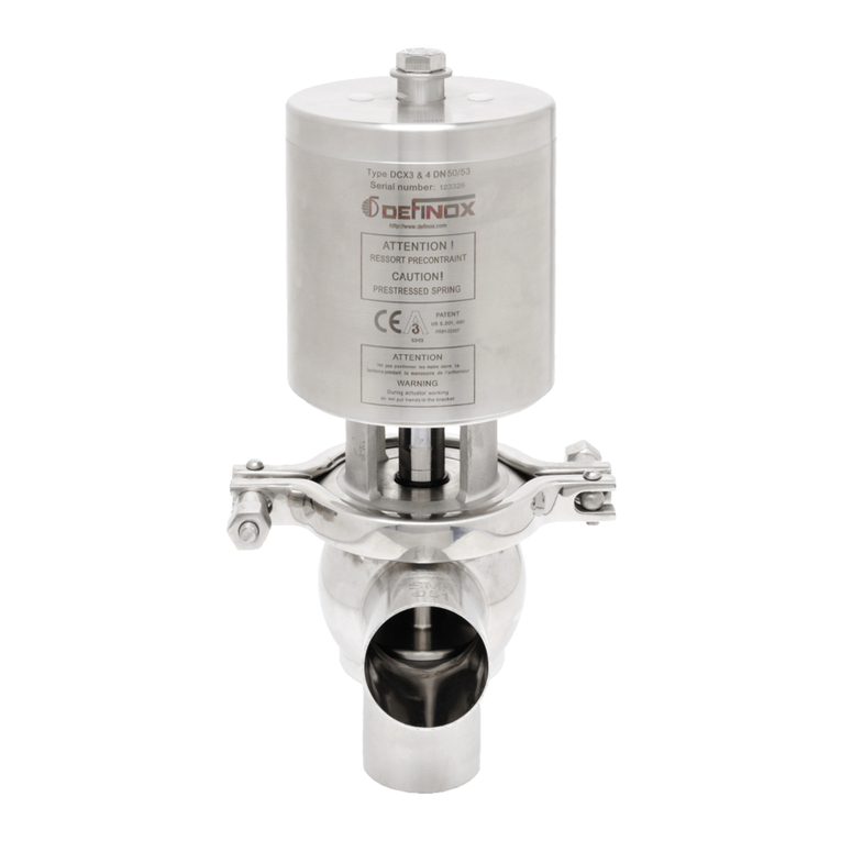
Definox
Definox DCX3 User manual
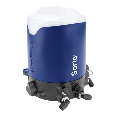
Definox
Definox Sorio Operation and maintenance manual
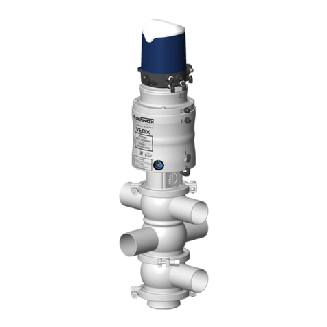
Definox
Definox VEOX SP 3 BODY Operation and maintenance manual
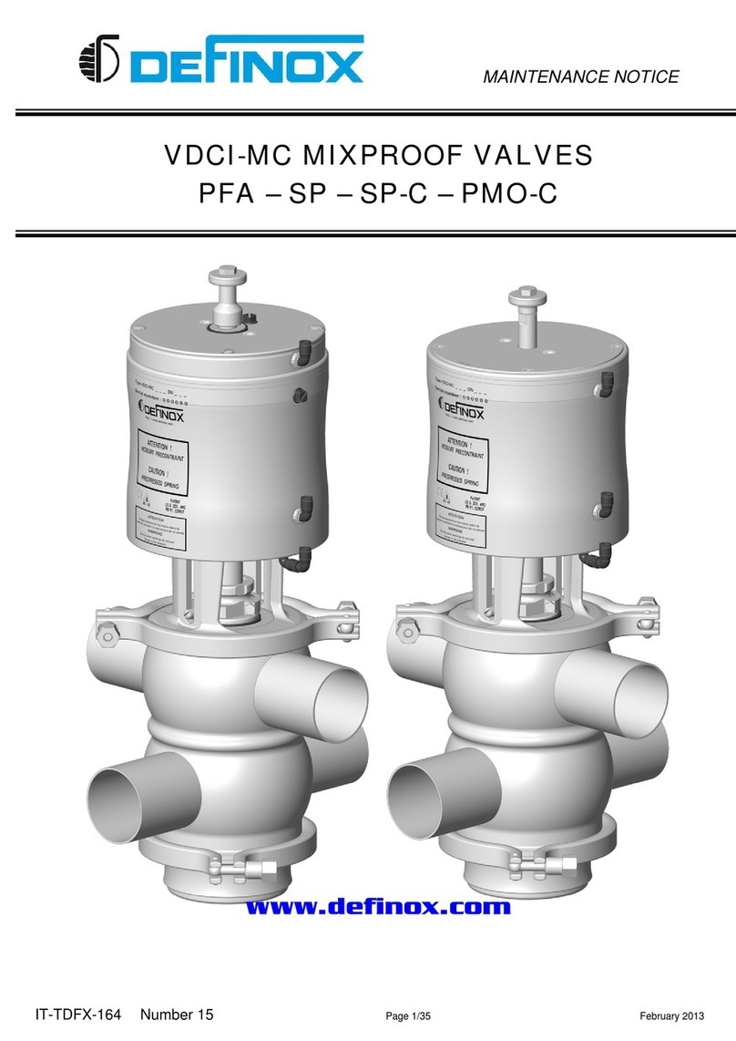
Definox
Definox VDCI-MC PFA User manual

Definox
Definox DCX3 Operation and maintenance manual

Definox
Definox DCX4 HP User manual
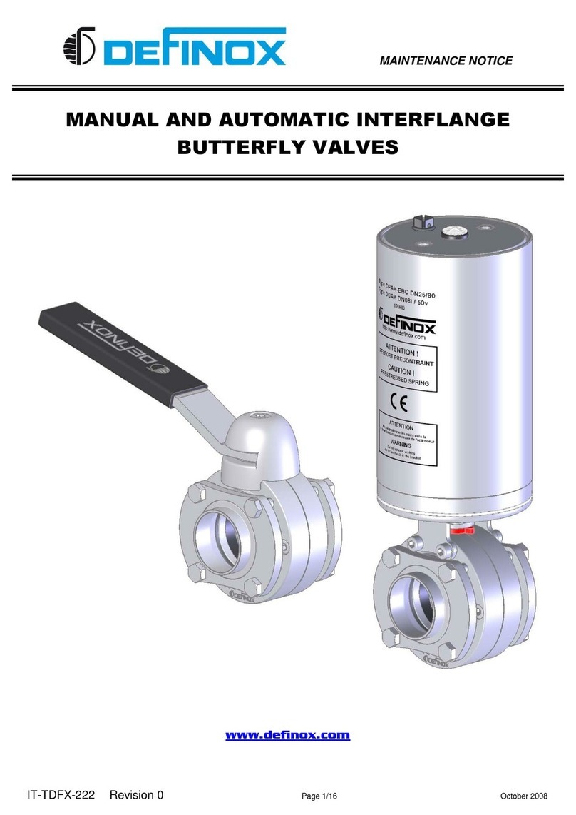
Definox
Definox DPX1EBC Operation and maintenance manual

Definox
Definox VEOX PMO Operation and maintenance manual

Definox
Definox Sorio Basic 1EV User manual
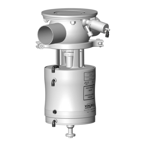
Definox
Definox VDCI-MC-FC Operation and maintenance manual

Definox
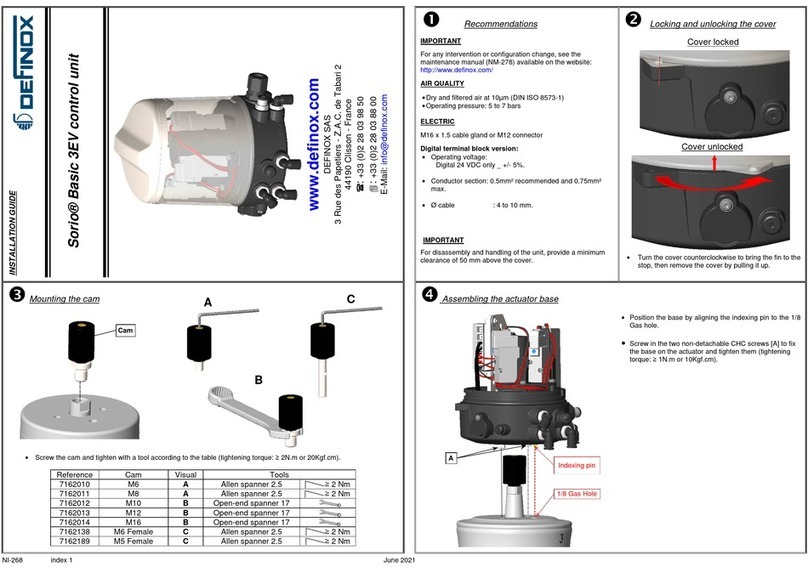
Definox DCX3 Operating and maintenance instructions
Definox
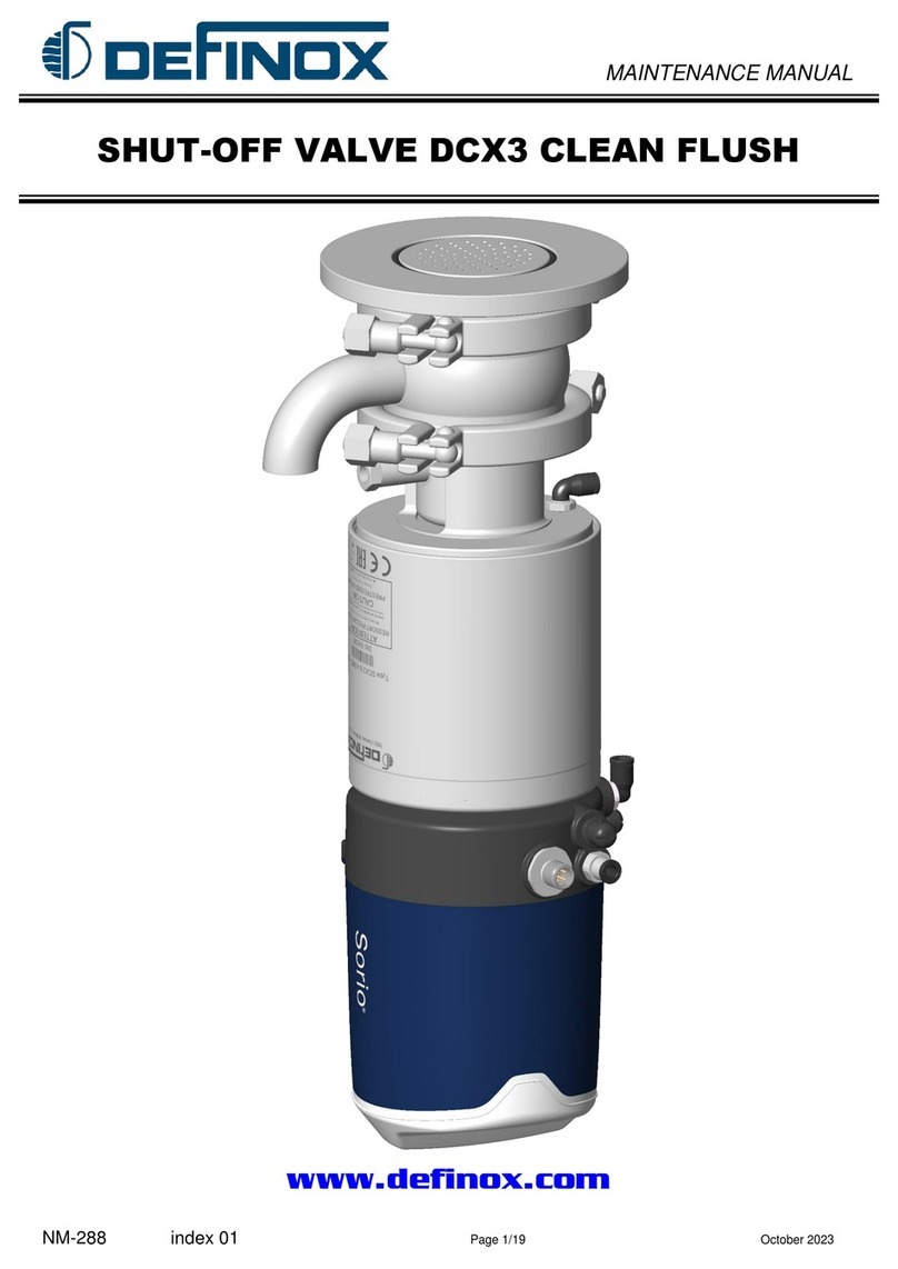
Definox Sorio Basic 3EV User manual
Definox
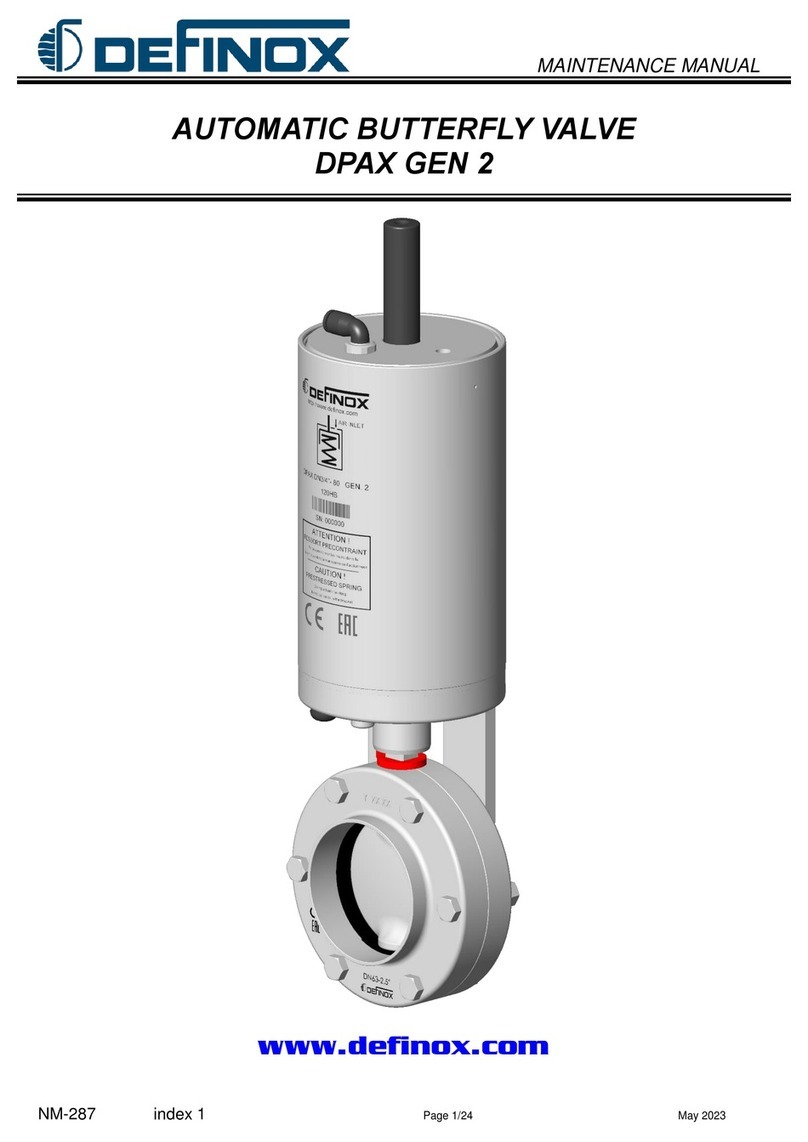
Definox DCX3 User manual
Definox
Definox DPAX GEN 2 User manual

Definox
Definox DCX3 Operation and maintenance manual

Definox
Definox DCX3 Operation and maintenance manual
Popular Control Unit manuals by other brands
Taco Comfort Solutions
Taco Comfort Solutions Geo-Sentry V100C3G1ZA024Q4A2 instruction sheet
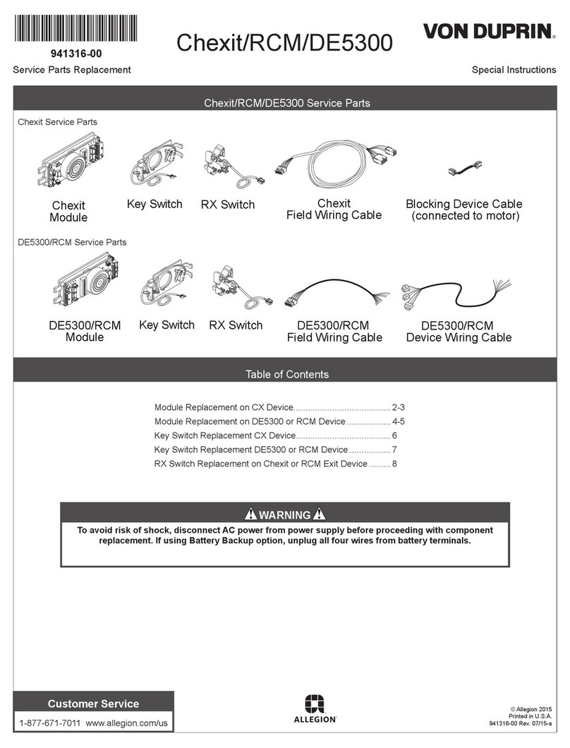
Von Duprin
Von Duprin DE5300 Special instructions
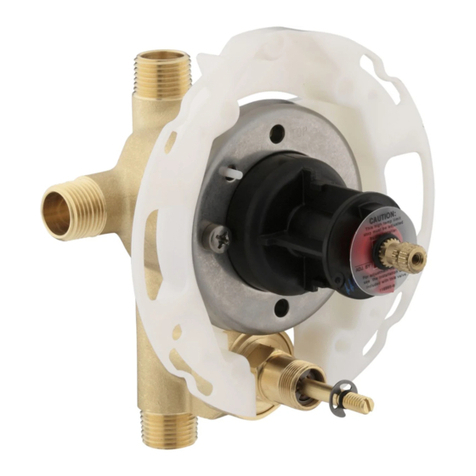
Kohler
Kohler K-304 Installation and care guide

Versum Materials
Versum Materials GASGUARD AP11 BSGS eV Asia Installation, operation & maintenance manual
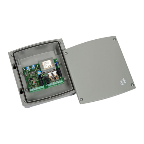
V2
V2 EASY-BASIC manual

VIA Technologies
VIA Technologies SOM-3000-STK quick start guide

