Definox DPAX User manual
Other Definox Control Unit manuals

Definox
Definox VEOX PMO Operation and maintenance manual
Definox
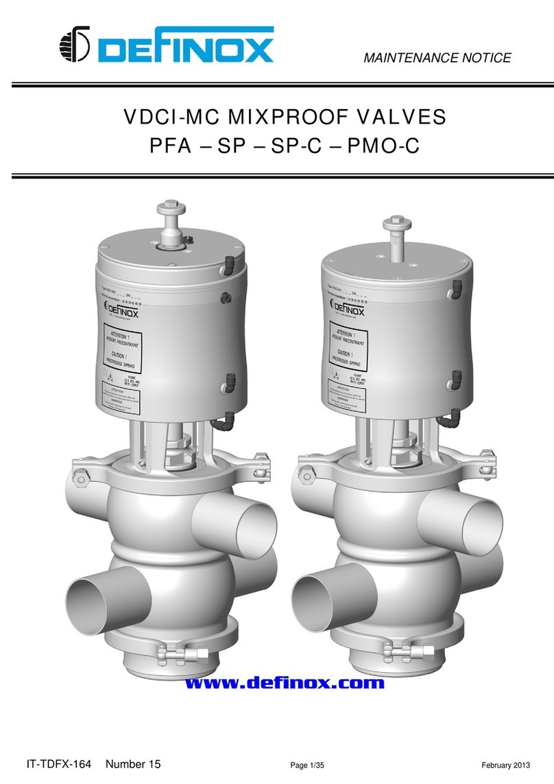
Definox VDCI-MC PFA User manual

Definox
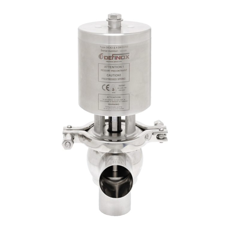
Definox DCX3 Operation and maintenance manual
Definox
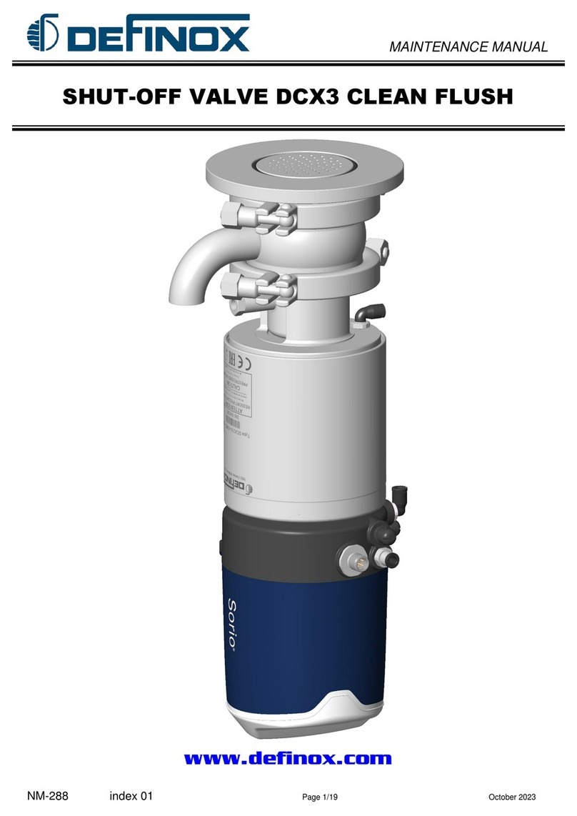
Definox DCX3 User manual
Definox
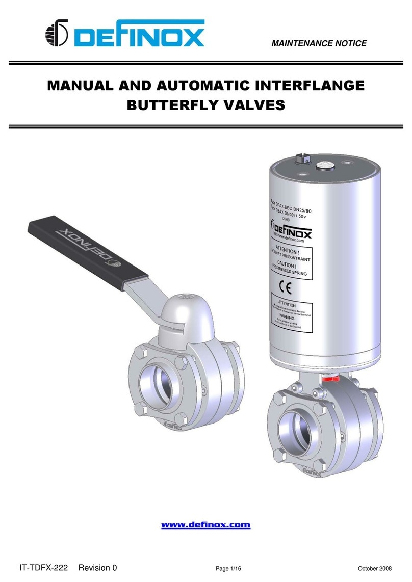
Definox DCX3 User manual
Definox
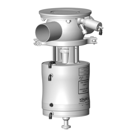
Definox DPX1EBC Operation and maintenance manual
Definox
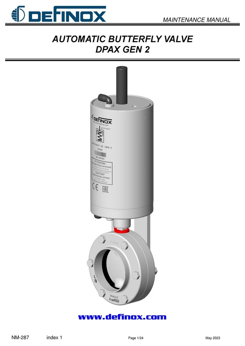
Definox DPAX GEN 2 User manual
Definox
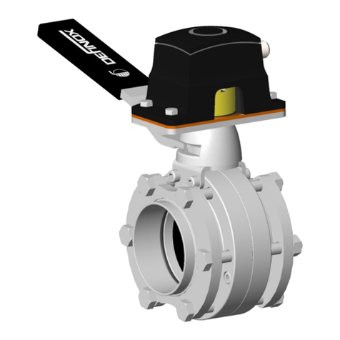
Definox VDCI-MC-FC Operation and maintenance manual
Definox
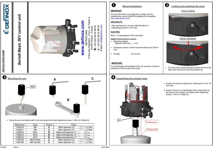
Definox Sorio Basic 3EV User manual
Definox
Definox DPX EBC User manual

Definox
Definox DCX4 HP User manual
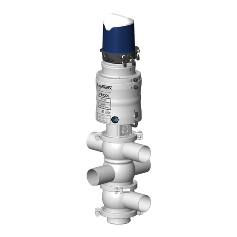
Definox
Definox VEOX SP 3 BODY Operation and maintenance manual

Definox
Definox Sorio Basic 1EV User manual

Definox
Definox ICS Operation and maintenance manual

Definox
Definox DCX3 Operation and maintenance manual

Definox
Definox DCX3 Operation and maintenance manual
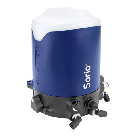
Definox
Definox Sorio Operation and maintenance manual

Definox
Definox DCX3 Operating and maintenance instructions
Popular Control Unit manuals by other brands
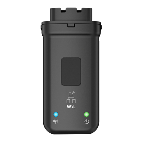
Goodwe
Goodwe Wi-Fi/LAN Kit Quick installation guide
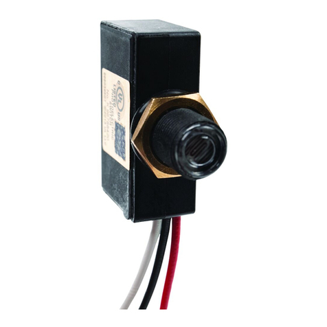
Intermatic
Intermatic K4621 installation manual
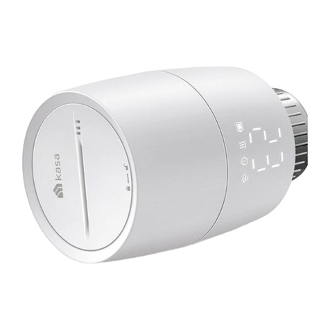
TP-Link
TP-Link kasa smart KE100 quick start guide
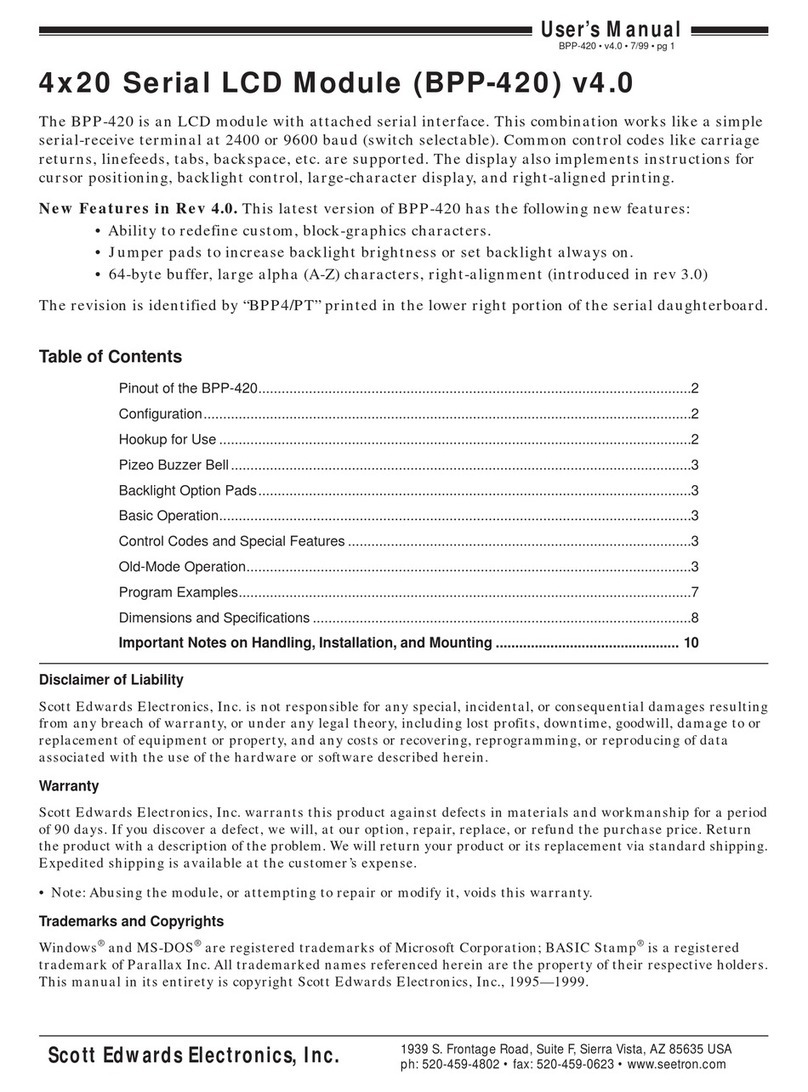
Scott Edwards Electronics
Scott Edwards Electronics BPP-420 user manual
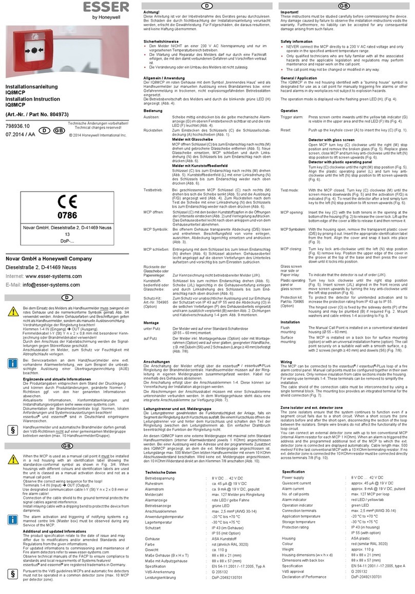
Honeywell
Honeywell 804973 Installation instruction
O&O
O&O LOG-BC Installation and operation manual
emmeti
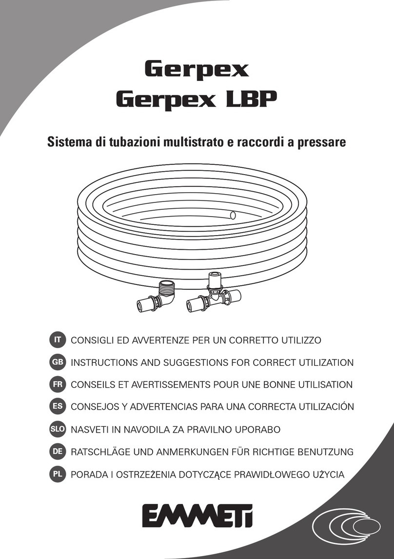
emmeti Gerpex INSTRUCTIONS AND SUGGESTIONS FOR CORRECT UTILIZATION
Bticino
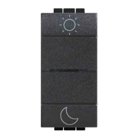
Bticino LN4574CWI quick start guide

Texas Instruments
Texas Instruments AM437x user guide
Dyna-Flo
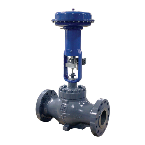
Dyna-Flo 350 Operation, Parts, and Instruction Manual
Quectel
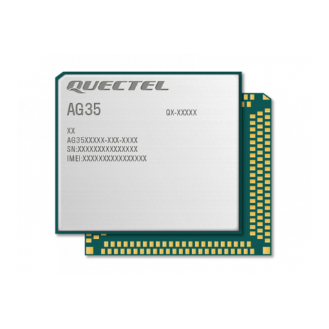
Quectel AG35 SMTP AT Command manual
Festo
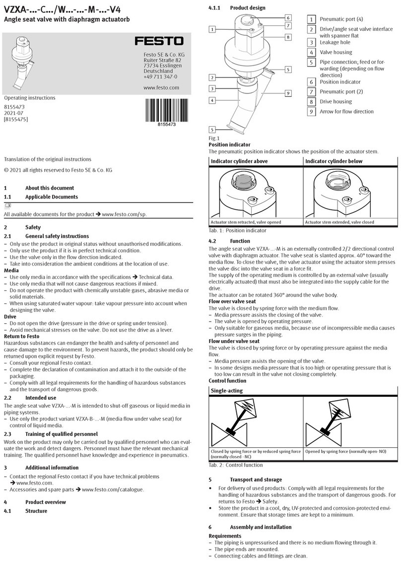
Festo VZXA-C/W-M-V4 Series operating instructions

TESTO
TESTO 0560 5600 quick start guide
Tunstall
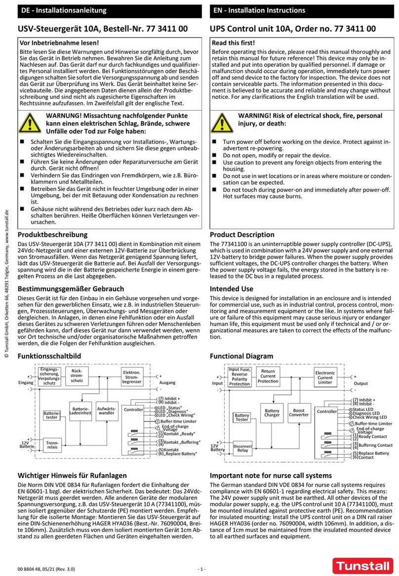
Tunstall 77 3411 00 installation instructions

White Rodgers
White Rodgers 50T35-743 installation instructions
SMC Networks
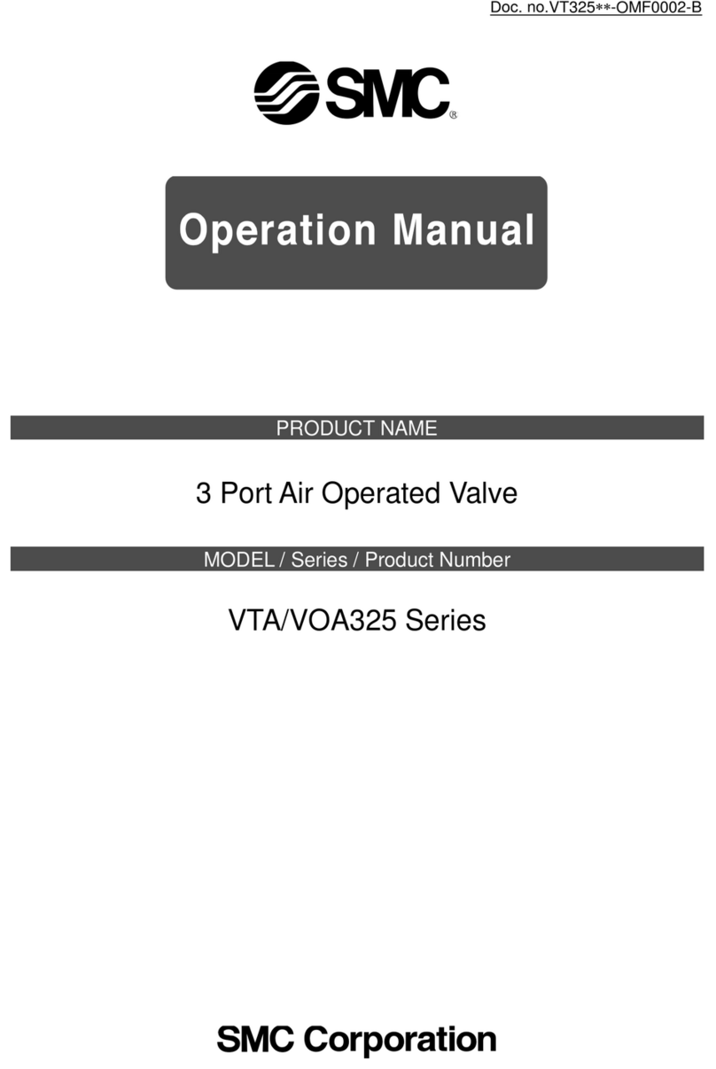
SMC Networks VOA325 Series Operation manual

Albalá Ingenieros, S.A.
Albalá Ingenieros, S.A. HLI3000C01 manual

Woodward
Woodward 8280-464 product manual

