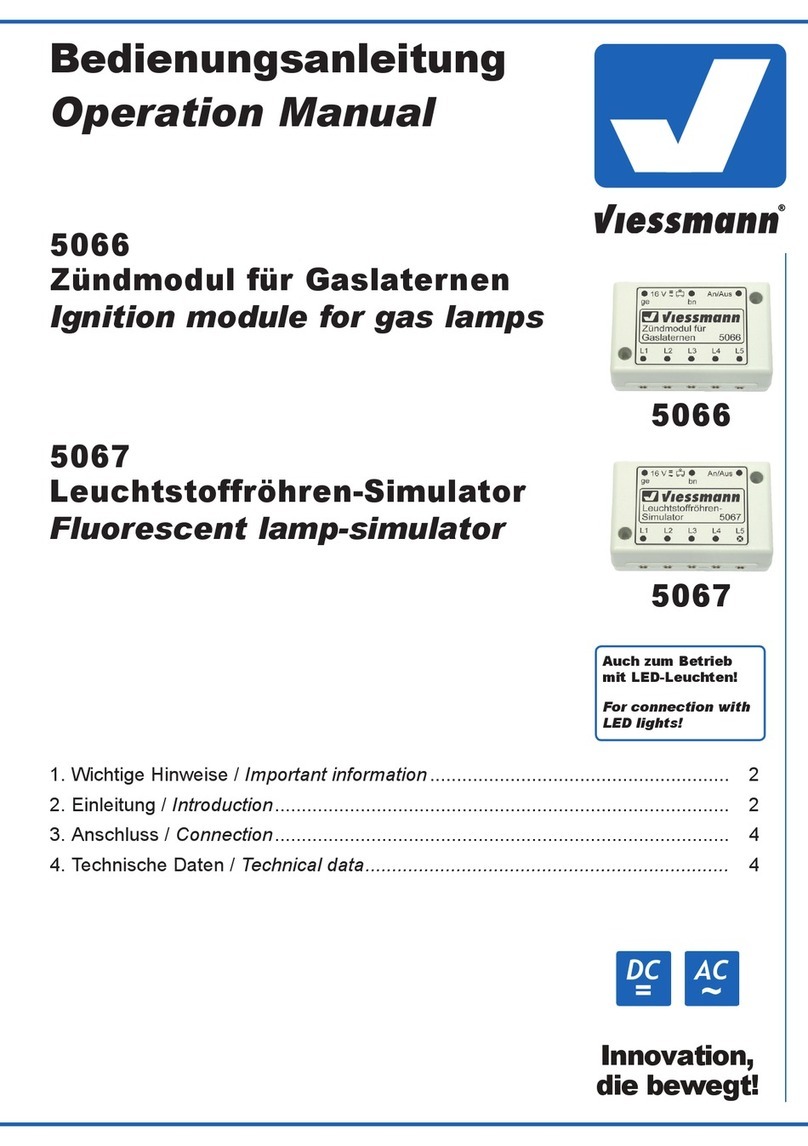
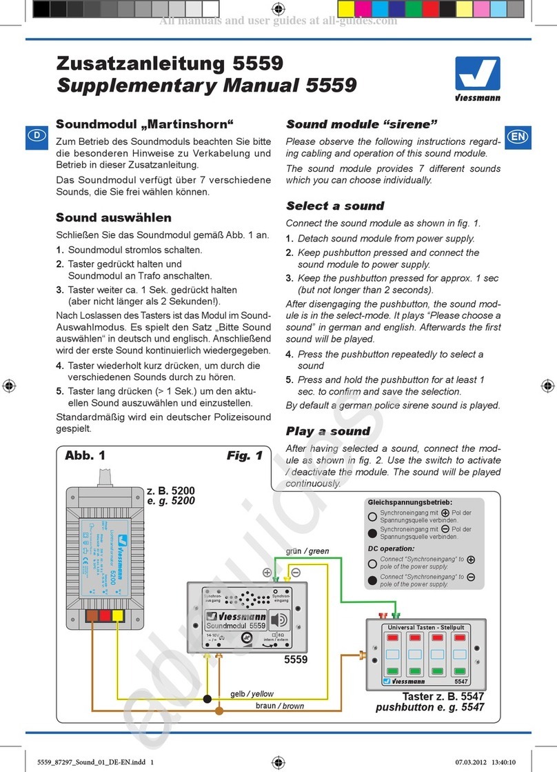
Viessmann SCU 123 User manual
Other Viessmann Control Unit manuals

Viessmann
Viessmann 5096 User manual

Viessmann
Viessmann VITOTRANS 353 Quick guide

Viessmann
Viessmann VITOTRONIC 100 Quick guide

Viessmann
Viessmann Vitotronic 100 HC1 Manual

Viessmann
Viessmann VITOTRONIC 100 User manual
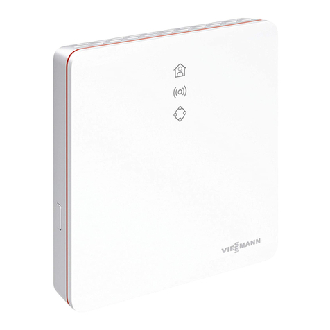
Viessmann
Viessmann VITOCONNECT OPTO2 User manual

Viessmann
Viessmann VITOTRONIC 100 GC1B Quick guide

Viessmann
Viessmann Vitotronic 100 HC1 Quick guide
Viessmann
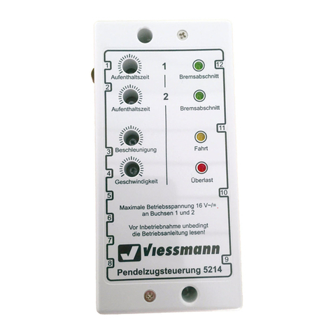
Viessmann 5214 User manual

Viessmann
Viessmann Vitotronic 100 GC1 Guide
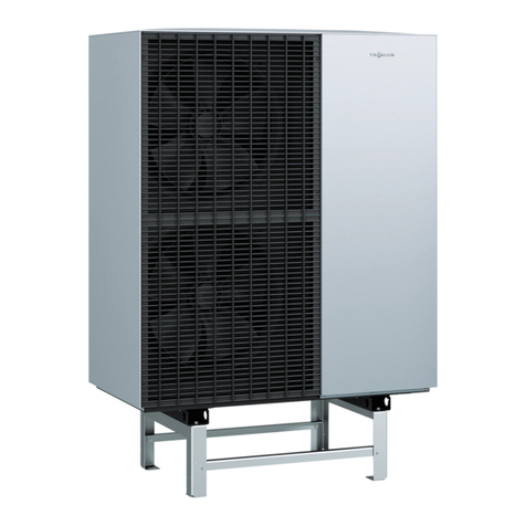
Viessmann
Viessmann VITOCAL 150-A Operating instructions

Viessmann
Viessmann Vitotrol 350 User manual

Viessmann
Viessmann VITOTRONIC 300-K User manual
Viessmann
Viessmann Vitocom 100 LAN1 Quick guide
Viessmann
Viessmann EM-EA1 extension Operating instructions
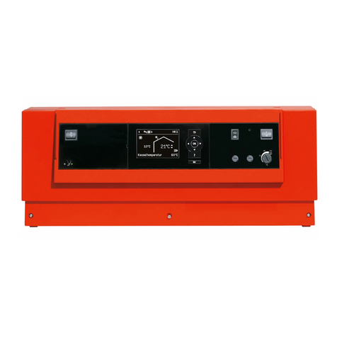
Viessmann
Viessmann VITOTRONIC 300 Quick guide

Viessmann
Viessmann Vitocom 100 LAN1 Technical manual

Viessmann
Viessmann PLC VITOCAL 350-HT PRO Operating instructions

Viessmann
Viessmann 5204 User manual
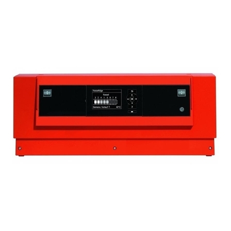
Viessmann
Viessmann VITOTRONIC 100 Operating instructions
Popular Control Unit manuals by other brands

Festo
Festo Compact Performance CP-FB6-E Brief description

Elo TouchSystems
Elo TouchSystems DMS-SA19P-EXTME Quick installation guide

JS Automation
JS Automation MPC3034A user manual

JAUDT
JAUDT SW GII 6406 Series Translation of the original operating instructions

Spektrum
Spektrum Air Module System manual

BOC Edwards
BOC Edwards Q Series instruction manual

KHADAS
KHADAS BT Magic quick start

Etherma
Etherma eNEXHO-IL Assembly and operating instructions

PMFoundations
PMFoundations Attenuverter Assembly guide

GEA
GEA VARIVENT Operating instruction

Walther Systemtechnik
Walther Systemtechnik VMS-05 Assembly instructions

Altronix
Altronix LINQ8PD Installation and programming manual


