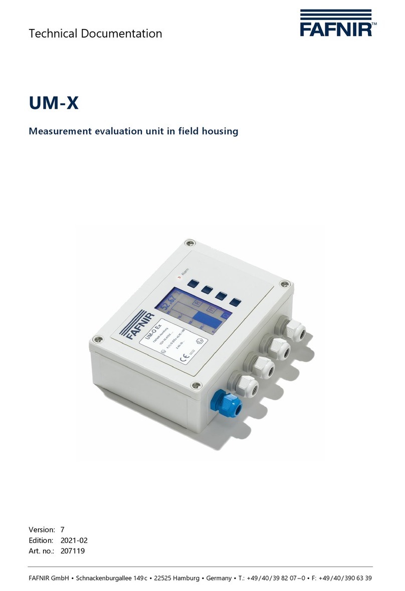
Deif TRI-2 User manual

Panorama rudder indicator
User's manual
4189350053D

1. General information
1.1 Disclaimer........................................................................................................................................................................................................................................ 3
1.1.1 Disclaimer.................................................................................................................................................................................................................................3
1.2 Product presentation...............................................................................................................................................................................................................3
1.2.1 and CAN........................................................................................................................................................................................................3
2. Before using the product
2.1 Initial steps..................................................................................................................................................................................................................................... 4
2.1.1 Remove transport lock.....................................................................................................................................................................................................4
2.1.2 Mounting.................................................................................................................................................................................................................................5
3. Setting up TRI-2
3.1 Connection.....................................................................................................................................................................................................................................6
3.2 Connection of analogue version......................................................................................................................................................................................6
3.2.1 ......................................................................................................................................................................................................................................... 6
3.2.2 Current input.......................................................................................................................................................................................................................6
3.2.3 Voltage input.......................................................................................................................................................................................................................6
3.2.4 Voltage input 3-wire........................................................................................................................................................................................................7
3.3 Adjustment and setup.............................................................................................................................................................................................................7
3.3.1 Voltage versions.................................................................................................................................................................................................................7
4. Setting up TRI-2 CAN
4.1 Connection and setup............................................................................................................................................................................................................. 8
4.1.1 CAN...............................................................................................................................................................................................................................8
5. Connections of CAN version
5.1 Connections...................................................................................................................................................................................................................................9
5.2 Single CAN setup.......................................................................................................................................................................................................................9
5.2.1 Setup example...................................................................................................................................................................................................................10
5.2.2 Make max. adjustment.................................................................................................................................................................................................11
5.3 Dual CAN setup.........................................................................................................................................................................................................................12
5.4 Remote dimmer........................................................................................................................................................................................................................13
5.4.1 and CAN remote dimmer..................................................................................................................................................................13
6. Technical information
6.1 Specifications.............................................................................................................................................................................................................................14
6.1.1 and CAN......................................................................................................................................................................................................14
User's manual 4189350053D EN Page 2 of 14

1. General information
1.1 Disclaimer
1.1.1 Disclaimer
DEIF A/S reserves the right to change any of the contents of this document without prior notice.
The English version of this document always contains the most recent and up-to-date information about the product. DEIF
does not take responsibility for the accuracy of translations, and translations might not be updated at the same time as the
English document. If there is any discrepancy, the English version prevails.
1.2 Product presentation
1.2.1 TRI-2 and TRI-2 CAN
The rudder angle indicator type and CAN is used for the indication of the rudder position on the bridge. The
light intensity can be changed by means of a built-in dimmer accessible on the rear plate of the indicator. Optional remote
dimming from a control panel can be used.
User's manual 4189350053D EN Page 3 of 14

2. Before using the product
2.1 Initial steps
2.1.1 Remove transport lock
Transport lock mounted
The transport lock (bright red plastic) is mounted to prevent the pointers from being
damaged under heavy vibration and shock (transportation). The transport lock must
be removed before connecting the indicator!
Removal of rear plate
Remove the rear plate screws).
Removal of transport lock
Gently draw the transport lock out with a hand. When inserting the transport lock
again, gently insert it between the scale guide (white plastic part inside) and the
housing (black part).
Transport lock view
Please keep the transport lock in case you need to ship the indicator after system
test, or in case you need to return the indicator to DEIF for service!
Mounting the rear plate
Tighten the screws only by hand and with a maximum at 0.5 nM torque to avoid
overtighten the screws.
User's manual 4189350053D EN Page 4 of 14

2.1.2 Mounting
and CAN have been designed for mounting on the ceiling of the bridge. The cables are connected through the
rear panel or through the ceiling.
Weight: Approx. 1.5 kg.
Make sure that the instrument is mounted on an even surface to prevent the instrument housing from deforming.
User's manual 4189350053D EN Page 5 of 14

3. Setting up
3.1 Connection
Depending on the ordered version of analogue or CAN version, different connections and settings apply. The
analogue versions of the allow only small adjustments whereas it is possible to make more adjustments on the CAN
version.
3.2 Connection of analogue version
3.2.1 TRI-2
After removing the rear panel, the connection terminals are visible. Cable dimensions between 0.2 and 2.5 mm2 can be used
for the terminals.
3.2.2 Current input
Terminal 1 Terminal 2 Pointer response (TRI-2 mounted in the ceiling)
- current out + current in
0/4 mA Max. left
10/12 mA Zero
20 mA Max. right
INFO
Not possible to make adjustments on with current input.
3.2.3 Voltage input
Terminal 1 Terminal 2 Pointer response (TRI-2 mounted in the ceiling)
+/- V in 0 V in
V Max. left
0 V Zero
V Max. right
0 V +V in
0 V Max. left
5 V Zero
10 V Max. right
User's manual 4189350053D EN Page 6 of 14

INFO
The voltage for illumination may be either 24 V AC or 24 V DC.
3.2.4 Voltage input 3-wire
Potentiometer R1 can be used to adjust the deflection of the instrument within of full scale to fit the scaling of the
indicator to the existing installation.
3.3 Adjustment and setup
When the instrument has been properly connected to the analogue rudder transmitter, it can be adjusted to ensure that
alignment is in correct position with the rudders. Mechanical zero adjustment is placed in the bottom of the instrument. It is
adjusted to zero with the rudder in position zero.
The rudder is now turned to maximum position. The instrument indication should be the same as the rudder angle. NOTE:
No zero adjustment on 0 to 20 mA and 4 to 20 mA versions. Potentiometer R1 can be adjusted if the instrument indication is
not the same as the rudder angle. Potentiometer R1 is placed on the left side of the three blue potentiometers.
Remember to remount the rear plate with all 4 screws to ensure the IP54 protection of the instrument.
3.3.1 Voltage versions
When the mechanical zero position has been adjusted, it is possible to make adjustments to the maximum position. The
rudder must be turned to the maximum position. Adjusting the potentiometer R3 will move the pointer of the
When adjusting the 3-wire version, the same procedure is used. But to adjust the maximum, the potentiometer R15 should
be used to adjust the maximum deflection.
The maximum range of the maximum deflection is 10 % of the input value.
User's manual 4189350053D EN Page 7 of 14

4. Setting up CAN
4.1 Connection and setup
4.1.1 TRI-2 CAN
On the CAN version, the connection terminals are also located under the rear plate on the analogue versions. To make
adjustment on sCAN and dual CAN versions, an encoder is used. The encoder (integrated push-button/rotating encoder) is
located between the two sets of connectors. The encoder is used for the entire set-up together with the two LEDs marked
1 and 2 located on each side of it.
INFO
Notice that the terminals have been numbered from right to left.
A CAN termination switch is placed on the left side of terminal 11. This switch terminates the CAN1 line with 120 Ohm when
set to ON (switch is pushed to the right, towards connector Normal position will be OFF = no termination (switch is
pushed to the left).
Note that only CAN1 has this termination possibility!
10 9 8 7
11
Terminals
CAN1 termination switch
OFF ON X3
User's manual 4189350053D EN Page 8 of 14

5. Connections of CAN version
5.1 Connections
Pin no. Function CANopen Note
1 Supply voltage V to 24 V DC Consumption 12 V
300 mA/24 V 150 mA
2 0 V DC "
3
CAN connection
CAN 2 H input CAN 2 line
4 CAN 2 L input "
5 CAN 2 GND "
6 NC "
7 CAN 1 H input CAN 1 line
8 CAN 1 L input "
9 CAN 1 GND "
10 Illumination Dimmer wiper Dimmer control via 1 kohm 2 W potentiometer
11 Dimmer ref. "
The label is located under the lid with the dimmer potentiometer.
5.2 Single CAN setup
The table describes the different settings which can be made for the sCAN version.
Depending on the selected operation, it is possible to make changes or see the factory settings of the
User's manual 4189350053D EN Page 9 of 14

Time-out: if a mode is entered and no changes made, a time-out of 5 minutes will ensure that the will return to normal
operation.
When a setting has been changed, save command must be used to save the change. This is done by pressing the mode
button for more than 5 seconds until the returns back to normal operation. If multiple changes are to be made, the
save command must be used after each change.
5.2.1 Setup example
In normal operation, a single flash on LED1 indicates that CAN protocol "Single CAN" is in use. If in doubt whether the
is ordered to the right protocol, this can be seen in menu 304 (303).
User's manual 4189350053D EN Page 10 of 14

INFO
Be aware that the protocol can only be set in the TRI-2 order process.
Going from normal operation mode to installation mode press the encoder for 5 seconds. Afterwards, in mode
200, presses of 1 seconds will result in jumps from mode 200 to 201 - 202 - 203 - 200. To save the settings, press the
encoder for 5 seconds. Notice that settings must be saved before entering the next mode. For example, a zero adjustment
performed in mode 200 must be saved before going to mode 201 for maximum adjustment.
If the advanced setup is needed, if for example the pointer direction has to be changed from CW to CCW, then go to mode
203 and press the encoder for 10 seconds to activate mode 301. Afterwards, every press of 1 second will result in jumps
from mode 301 to 302 - 303 - 304 - 305 - 301. Notice that settings must be saved (press 5 seconds) before entering the
next mode. To leave advanced setup, press the encoder for 5 seconds.
During setup, the input value (if available) is indicated on the instrument.
Time-out: after 5 minutes without any change, the unit will return to normal operation without saving.
5.2.2 Make max. adjustment
Adjustment of the can be set for max. and zero. The will then internally make a linear adjustment from minimum
to zero and to maximum.
Max. is defined on the left side of the opposite the cable input; see picture below:
clockwise rotation
When the rotation of the is set to clockwise, the rudder must be positioned at port side when making the max.
adjustment. If the rotation counter is clockwise, the rudder must be positioned at starboard when adjusting max. The
procedure to adjust maximum is described below:
1. Set rudder at port side maximum
2. Enter installation setup
3. Press the tumble wheel once, and both LEDs will be yellow
4. Turn the tumble wheel until the pointer moves to the right position on the scale
5. Save the value by pressing the tumble wheel for more than 5 seconds. The returns to normal mode.
User's manual 4189350053D EN Page 11 of 14

5.3 Dual CAN setup
In normal operation, a double flash on LED 1 and 2 indicates that CAN protocol "Dual CANopen" is in use. If the CAN bus is
not detected, wrong writing or wrong protocol may have been ordered.
User's manual 4189350053D EN Page 12 of 14

Enter "Advanced mode 304" to see which protocol has been ordered. Note that the shown CAN protocol can't be changed
from the menu.
If a needs another protocol, a new indicator must be ordered.
Time-out: after 5 minutes without any change, the unit will return to normal operation without saving.
5.4 Remote dimmer
5.4.1 TRI-2 and TRI-2 CAN remote dimmer
If remote dimmer is preferred, the built-in dimmer potentiometer can be removed from the indicator (after dismantling the
rear plate) and mounted e.g. in a control panel. A plug to seal the hole in the rear plate is included on delivery.
The following example is for the with analogue input, but it is similar for the CAN version (however, only 2 wires
to the potentiometer is needed).
NOTICE
Connecting the wiper (centre pin) on the dimmer potentiometer to a wrong terminal in the TRI-2 may
destroy the illumination circuit!
Exercise care and connect the wire coming from the wiper (centre pin on the potentiometer) to the terminal
marked 1 (wiper) in (see drawing below). (This only applies for not
124
35
Potentiometer front
Button
24
2.5 -0.2
max 20
max 19.8
ø 24.2
11.9 13
8
6
10.2
2.6 +0.1
12.2 +0.3
M10 x 75
11 12 13
Red
White
Orange
11: Red
12: Orange
13: White
INFO
If dimming via CANbus is used on CAN, the manual dimmer will be off.
User's manual 4189350053D EN Page 13 of 14

6. Technical information
6.1 Specifications
6.1.1 TRI-2 and TRI-2 CAN
Key specifications
Compass safety distance 1 metre
Auxiliary voltage:
24 V AC/DC % (illumination only)
CAN 12 to 24 V DC % (note: DC
Consumption:
Max. 3 W
CAN Max. 4 W
Cable dimensions 0.2 to 2.5 mm2
Cable entries Via two PG 13.5 cable glands
Cable outer diameter mm
Error indications
TRI-2 CAN
Pointer totally CCW indicates no aux. voltage connected to the instrument
Pointer totally CW indicates no CAN data received
Pointer totally CCW or CW can also indicate internal processor error or CAN data out of range
CAN bus problems can be diagnosed using the colour sequence of the two LEDs behind the
rear plate (see setup tables).
NOTE:
with analogue input, no special error indications are available
User's manual 4189350053D EN Page 14 of 14
This manual suits for next models
1
Table of contents
Other Deif Measuring Instrument manuals

Deif
Deif Insight User manual

Deif
Deif MIQ96-2 User manual

Deif
Deif MIB 7000 User manual

Deif
Deif AGC 150 User manual

Deif
Deif XDi Series User manual

Deif
Deif MIC-2 MKII User manual

Deif
Deif XL User manual

Deif
Deif ADL-111Q96/xxVDC Series Installation instructions

Deif
Deif MIC-2 MKII Operating and maintenance instructions

Deif
Deif WSI User manual
Popular Measuring Instrument manuals by other brands
Larson Davis
Larson Davis SoundAdvisor 831C Reference manual

Keysight
Keysight N2790A user guide

Mobileye
Mobileye COLLISION AVOIDANCE SYSTEM reference guide

3Dazer
3Dazer DZ-ID1601 user manual
KLEIBER
KLEIBER KG 315-K USB Operation manual
Research Instruments
Research Instruments HandiLaz Mini quick start guide

