manuals.online logo
Brands
  1. Home
  2. •
  3. Brands
  4. •
  5. Dell
  6. •
  7. Network Hardware
  8. •
  9. Dell FS7500 Manual

Dell FS7500 Manual

1Unpack the Shipping Box
Caution: Protect sensitive hardware. Make sure you
use an electrostatic wrist strap or similar form of protection
when handling hardware.
The FS7500 comes packed in one box or two boxes, depending
on your location. In the single box configuration, the BPS is
packed on top of the box containing the controllers.
Place all components on a stable surface.
Controller Contents:
• 2 controller units
• 2 controller bezels
• 6 power cables
• 2 controller rail kits
• Documentation
BPS Box Contents:
• BPS chassis with 2 installed power modules
• Accessory box with bezel, 2 USB cables, 2 hook-and-loop
fastener strips, and 2 REPO port connectors
• Rail kit for the BPS
2Connect BPS Batteries and Install
the BPS in a Rack
Note: Install the hardware starting from the bottom of the rack.
You will install the two controllers on top of the BPS.
1. Obtain the rail kit from the BPS shipping box.
2. Remove the power modules from the BPS.
3. Install the rails into the rack.
4. Install the empty BPS chassis into the rack.
5. Connect the battery in each BPS power module:
a. Remove the power module cover. Do not disconnect the
ribbon cable.
b. Remove the battery from the power module.
c. Rotate the battery 180 degrees (turn back to front).
d. Reinstall the battery in the power module.
e. Attach the power module cover.
6. Install the 2 power modules in the BPS chassis.
Setting Up EqualLogic FS7500 Hardware
3Install the Controllers in the Rack
For each controller, perform the following steps:
1. Obtain the controller rail kit from the controller shipping box.
2. Install the rails in the rack.
3. Pull out the inner sliding rails until they lock into place.
4. Lower the controller onto the rails, starting with the rear.
5. Fit the screws into the J slots on the rails.
6. Slide the controller into the rack.
7. Press the release latch on the side of the rail, and slide the
controller all the way into the rack.
After you install the EqualLogic FS7500 hardware in a rack, it should look similar to the
figure below.
4Connect the BPS and Controllers to Power
Warning: Make sure the voltage of your power source is compatible with the voltage rating of the BPS. If the power source voltage
is too low, the BPS will not activate. If the voltage is too high, the BPS can be damaged.
1. Connect each BPS power module to a separate power source using the included power cables.
2. Use the hook-and-loop fastener strips to secure the power cable to the latch on each power module.
3. Turn on the power to each BPS module and make sure it is operational.
For each controller, perform the following steps:
1. Connect the controller to a power source.
2. Connect the controller to the power output
receptacle on a BPS power module.
3. Using one of the USB cables included in the
BPS shipping box, connect the controller to the
USB port on the same BPS power module.
4. Turn on the power to the controller and make
sure it is operational.
FS7500 Installation
Before You Begin
This is a condensed reference. Read the Installation Guide (provided in the box) for complete installation information.
Register for an EqualLogic Customer Support account. If you do not have a Customer Service Support account, go to
support.dell.com/EqualLogic and create one. Download and read the PS Series Release Notes from the support site. The Release
Notes contain the latest product information.
Environmental Requirements
Make sure the installation location meets the power, cooling, and ventilation requirements in the Installation and Setup manual, located
in the shipping box.
Required Hardware (Not Supplied)
• 19-inch(48.3cm)four-posttool-lessrack
• Ethernetcables:Youneed13Category5EorCategory6EthernetcableswithRJ45connectors(foreachFS7500controller)
• 2networkswitches
Installation Guidelines
The EqualLogic FS7500 hardware configuration consists of two FS7500 Controller units and one FS7500 Backup Power Supply (BPS)
unit. The BPS is required even if you have an uninterruptible power supply system in your environment. Install the three hardware
components adjacent to one another in the same rack.
Additional Information About SANs
For EqualLogic best practices, whitepapers, reference architectures, and sizing guidelines for enterprise applications and SANs, refer
to the Dell Storage Community at http://dell.to/sM4hJT.
SoftwareConfiguration Methods
PS Series Storage Arrays
Software Configuration
PSSeries Groups
Step1: Install the Host Integration Tools
Step2: Collect Configuration Information
Toconfigure the PS Series software, you need the information
inthe following tables.
CHAPpassword
Groupname
GroupIP address
Membership
password
Administration
password
CHAPusername
GroupConfiguration
RAIDpolicy
ArrayConfiguration
Membername
Defaultgateway
Subnetmask
ArrayIP address
RAIDpolicy
Multi-MemberPS Series Group
Group1
PS SERIES STORAGEARRAYS
Installation & Setup Manual
Chassis Types4, and 5
2
1
1
Gb 2
Gb 3
Gb 4
Gb
ST: JTKVVN1
Exp Svc Code:
43147463149
2
1
1
Gb 2
Gb 3
Gb 4
Gb
ST: JTKVVN1
Exp Svc Code:
43147463149
REPO OUT REPOIN
OUTPUT
250V-10A
INPUT 200 - 240V
REPO OUT REPOIN
OUTPUT
250V-10A
INPUT 200 - 240V
To BPS power
module USB To BPS power
module input
To Power Source 1
To Power Source 2
To Power Source 1
To Power Source 2
To BPS power
module USB To BPS power
module input
Setting Up EqualLogic FS7500 Hardware
Setting Up EqualLogic FS7500 Hardware (continued)
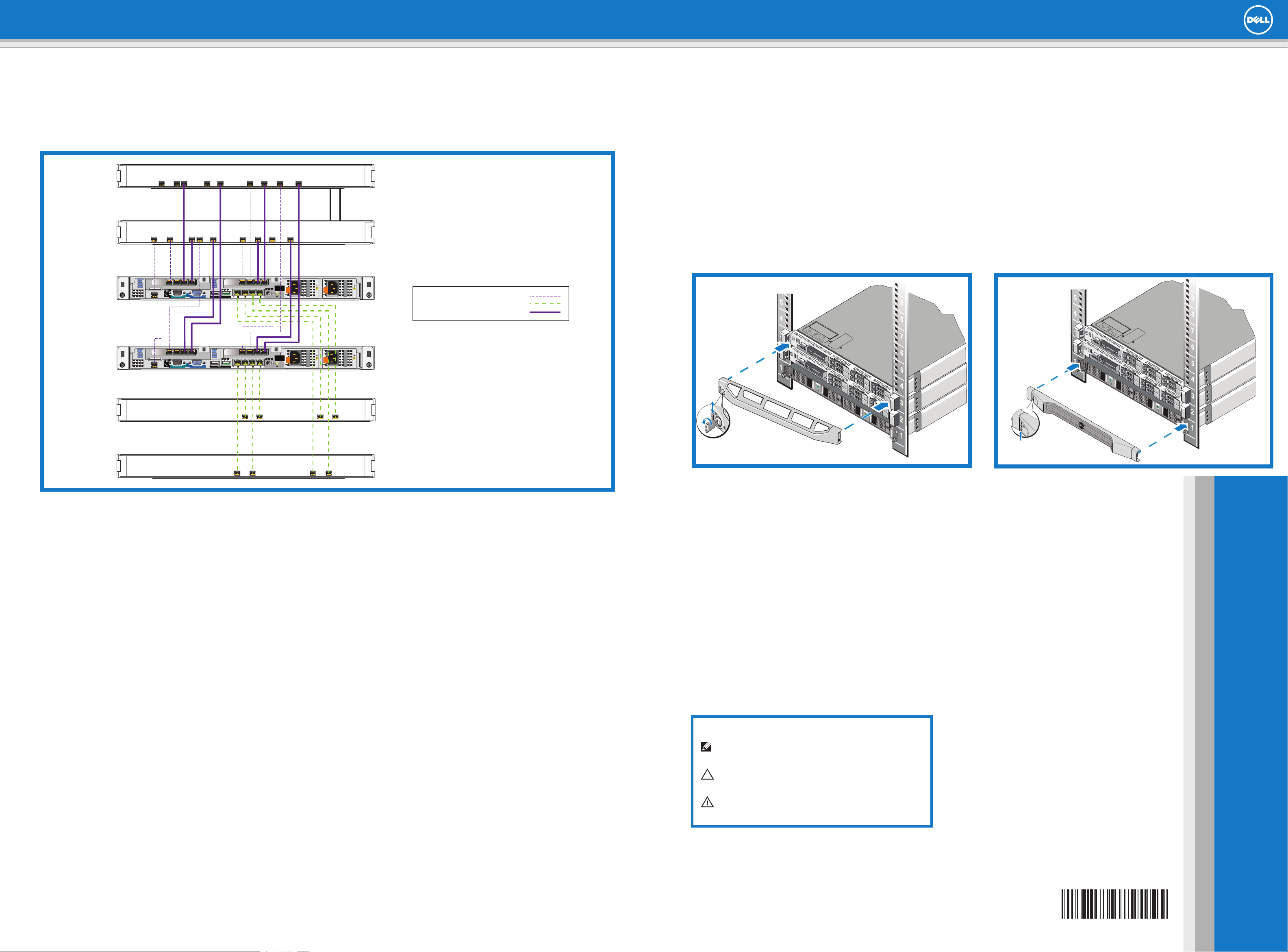
5Connect the Controllers to the Networks
Cabling Configuration Using Redundant Network Switches.
NOTE: The BPS and power connections are not shown.
Hardware Installation is Complete!
Your array hardware should now be up and running. If it is not, make sure that you have successfully completed all of the
steps described in this poster.
If you are still experiencing problems, see the Installation Guide for additional installation information.
The Installation Guide also provides technical support and customer service information.
Forlivetechnicalsupport,call1-800-945-3355.
What to do Next
Next, configure the NAS Service. See the EqualLogic FS7500 Installation Guide for information.
6Attach the Controller and BPS Bezels
For each controller, see the figure below and perform these steps:
1. Insert the right side of the bezel into the slot on the right side of the controller.
2. Push the bezel toward the left side of the controller.
3. Lift the latch on the left side of the bezel.
4. Engage the bezel with the left side of the controller chassis.
5. Release the latch.
6. Use the key to lock the bezel.
For the BPS, see the figure below right and perform these steps:
1. Gently fit the bezel onto the right side of the BPS.
2. Lift the latch on the left side of the bezel.
3. Push the left side of the bezel onto the left side of the chassis to engage the bezel with the front of the BPS.
4. Release the latch.
Printed in U.S.A.
Printed on recycled paper.
40VCM rev.A01
Information in this document is subject to change without notice.
Reproduction in any manner whatsoever without the written
permission of Dell EqualLogic is strictly forbidden.
Dell and EqualLogic are trademarks of Dell Inc.
Copyright 2012 Dell Inc. All rights reserved.
40VCMA01
Notes, Cautions, and Warnings
A NOTE symbol indicates important information that helps you make
better use of your hardware.
A CAUTION indicates either potential damage to hardware or loss of
data and tells you how to avoid the problem.
A WARNING symbol indicates a potential for property damage,
personal injury, or death.
Internal and SAN
Network Switches
Client
Network Switches
21
1
Gb 2
Gb 3
Gb 4
Gb
ST: JTKVVN1
Exp Svc Code:
43147463149
21
1
Gb 2
Gb 3
Gb 4
Gb
ST: JTKVVN1
Exp Svc Code:
43147463149
Internal Network: Small dashes (purple)
Client Network: Long dashes (green)
SAN connections: Solid line (purple)
Note: If you use VLANs within your switch stack, the
internal and SAN networks must be in the same VLAN.
Network Requirements
Your EqualLogic FS7500 system comes with a Dell enterprise deployment service. A representative from Dell enterprise services will be contacting you to
install the FS7500 system. Use these instructions in addition to the EqualLogic FS7500 Installation and Setup Manual as a guideline to prepare your net-
work to successfully install and run the FS7500 in your environment. For questions regarding these requirements, contact your Dell deployment service
engineer or Dell Technical Support.
The Dell FS7500 has three kinds of networks:
• Client Network: Enables the FS7500 system to connect to your user clients for file data access.
• SAN Network: Enables the FS7500 system to connect to the EqualLogic PS Series SAN for storing user data.
• Internal Network: Enables the FS7500 controller nodes to engage in internal communication required for failover and heartbeat.
The SAN and internal network connections (hereafter, “SAN/Internal”) are connected to the same set of Ethernet switches. Dell recommends using
separate switches for the client network than for the SAN/Internal network.
Before installing the FS7500, meet these requirements:
1. Category5/6cables:26networkcablesarerequiredforeachFS7500system.UseCategory5cablesonlyiftheyadheretotheTIA/EIATSB95
standard.
2. If you rack and cable the FS7500 system yourself, follow the cabling diagram and instructions listed in the EqualLogic FS7500 Installation and Setup
Manual included with your FS7500 product. Dell strongly recommends using a highly available network topology for both your SAN/Internal and client
networks.
3. Enable Spanning Tree Protocol/Port Fast on the SAN/Internal network switches.
4. Enable Flow Control on the SAN/Internal and client network switches.
5. Enablejumboframes(tosupportaframesizeof9000bytes)ontheSAN/Internalnetworkswitches.NotethatDellPowerConnectswitchesmustbe
 configuredto9216MTU.SwitchesfromvendorsotherthanDellmightrequireadifferentMTUconfigurationtoacceptframesof9000bytessize.
6. Disable Unicast storm control on the SAN/Internal switches.
7. You can use VLANs, but they are not required. If you use VLANs on your switches, the SAN and internal networks must be in the same VLAN.
8. IPv6 must be enabled on SAN/Internal switches for successful discovery of FS7500 controllers.
Additional Notes
1. Jumbo frames are required only on the SAN/Internal network. The client network on the FS7500 is set to 1500 MTU by default. However, you can
modify the setting on client network switches to enable jumbo frames if required.
2. All Ethernet ports of FS7500 communicate at 1 Gbps speed except the IPMI ports on the SAN/Internal network, which communicate at 100 Mbps only. If
you are connecting the FS7500 SAN/Internal network to 10 Gb Ethernet switches, ensure that the switch ports to which the FS7500 IPMI connections
are connected can operate at 100 Mbps speed and the rest of the switch ports connected to FS7500 can operate at 1 Gbps.
3. Do not connect the SAN/Internal network ports to a router.

Other manuals for FS7500

3

Other Dell Network Hardware manuals

Dell Virtual Edge Platform 4600 User manual

Dell

Dell Virtual Edge Platform 4600 User manual

Dell 53-1002116-01 Service manual

Dell

Dell 53-1002116-01 Service manual

Dell PowerEdge M1000e User manual

Dell

Dell PowerEdge M1000e User manual

Dell VEP4600 User guide

Dell

Dell VEP4600 User guide

Dell EMC Virtual Edge Platform 1405 Series User guide

Dell

Dell EMC Virtual Edge Platform 1405 Series User guide

Dell OptiPlex Small Form Factor 7010 User manual

Dell

Dell OptiPlex Small Form Factor 7010 User manual

Dell EMC NX3240 User instructions

Dell

Dell EMC NX3240 User instructions

Dell VxRail P670F Manual

Dell

Dell VxRail P670F Manual

Dell PowerVault 122T SDLT 320 User manual

Dell

Dell PowerVault 122T SDLT 320 User manual

Dell SonicWALL NSA E6500 User manual

Dell

Dell SonicWALL NSA E6500 User manual

Dell AX150 Reference guide

Dell

Dell AX150 Reference guide

Dell PowerEdge XR4000z Manual

Dell

Dell PowerEdge XR4000z Manual

Dell Safeguard 5242LR User manual

Dell

Dell Safeguard 5242LR User manual

Dell 210-APGV User manual

Dell

Dell 210-APGV User manual

Dell SonicWALL SuperMassive 9600 User manual

Dell

Dell SonicWALL SuperMassive 9600 User manual

Dell XC720xd User manual

Dell

Dell XC720xd User manual

Dell PowerFlex R750 User manual

Dell

Dell PowerFlex R750 User manual

Dell PowerVault NX3300 User instructions

Dell

Dell PowerVault NX3300 User instructions

Dell 5821E User manual

Dell

Dell 5821E User manual

Dell MC SD-WAN Edge 3400 Advanced User manual

Dell

Dell MC SD-WAN Edge 3400 Advanced User manual

Dell SonicWALL NSA E8510 User manual

Dell

Dell SonicWALL NSA E8510 User manual

Dell PowerVault TL4000 User manual

Dell

Dell PowerVault TL4000 User manual

Dell PowerVault NX3200 User manual

Dell

Dell PowerVault NX3200 User manual

Dell PowerVault NX3610 User manual

Dell

Dell PowerVault NX3610 User manual

Popular Network Hardware manuals by other brands

Parker Aries AR-08AE user guide

Parker

Parker Aries AR-08AE user guide

Shure AD600-DC manual

Shure

Shure AD600-DC manual

Allnet ALL1682504 Quick installation

Allnet

Allnet ALL1682504 Quick installation

Toshiba RemotEye II Quick installation guide

Toshiba

Toshiba RemotEye II Quick installation guide

FieldServer FS-8700-74 Driver manual

FieldServer

FieldServer FS-8700-74 Driver manual

Primex BC100 install guide

Primex

Primex BC100 install guide

DPS Telecom NetGuardian 216 G3 quick start guide

DPS Telecom

DPS Telecom NetGuardian 216 G3 quick start guide

GE TruVision NVR 40 quick start guide

GE

GE TruVision NVR 40 quick start guide

D-Link DES-1228 - Web Smart Switch Reference manual

D-Link

D-Link DES-1228 - Web Smart Switch Reference manual

Siemens RUGGEDCOM ROX II user guide

Siemens

Siemens RUGGEDCOM ROX II user guide

G-Technology G-RACK 12 user manual

G-Technology

G-Technology G-RACK 12 user manual

Castelle Enterprise Getting started guide

Castelle

Castelle Enterprise Getting started guide

Lorex NR800 Series instruction manual

Lorex

Lorex NR800 Series instruction manual

ALIBI ALI-NVR3308P Quick setup guide

ALIBI

ALIBI ALI-NVR3308P Quick setup guide

RTP 3108 Technical manual

RTP

RTP 3108 Technical manual

MikroTik netPower 15FR quick start

MikroTik

MikroTik netPower 15FR quick start

MKC eNetIO-1-a quick guide

MKC

MKC eNetIO-1-a quick guide

eks x-light manual

eks

eks x-light manual

manuals.online logo
manuals.online logoBrands
  • About & Mission
  • Contact us
  • Privacy Policy
  • Terms and Conditions

Copyright 2025 Manuals.Online. All Rights Reserved.