manuals.online logo
Brands
  1. Home
  2. •
  3. Brands
  4. •
  5. Dell
  6. •
  7. Server
  8. •
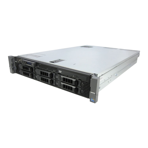
  9. Dell PowerEdge 6400 User manual

Dell PowerEdge 6400 User manual

ZZZGHOOFRP
VXSSRUWGHOOFRP
'HOO3RZHU(GJH[DQG[6\VWHPV
6&6,%$&.3/$1(237,21
73JXGbk2.book Page 3 Wednesday, May 17, 2000 4:49 PM
1RWHV1RWLFHV&DXWLRQVDQG:DUQLQJV
Throughout this guide, blocks of text may be accompanied by an icon and printed in
bold type or in italic type. These blocks are notes, notices, cautions, and warnings,
and they are used as follows:
NOTE: A NOTE indicates important information that helps you make better use of
your computer system.
127,&($127,&(LQGLFDWHVHLWKHUSRWHQWLDOGDPDJHWRKDUGZDUHRUORVV
RIGDWDDQGWHOOV\RXKRZWRDYRLGWKHSUREOHP
&$ 7,21$&$ 7,21LQGLFDWHVDSRWHQWLDOO\KD]DUGRXVVLWXDWLRQZKLFKLI
QRWDYRLGHGPD\UHVXOWLQPLQRURUPRGHUDWHLQMXU\
:$51,1*$:$51,1*LQGLFDWHVDSRWHQWLDOO\KD]DUGRXVVLWXDWLRQZKLFK
LIQRWDYRLGHGFRXOGUHVXOWLQGHDWKRUVHULRXVERGLO\LQMXU\
____________________
Information in this document is subject to change without notice.
© 2000 Dell Computer Corporation. All rights reserved.
Trademarks used in this text: Dell, the DELL logo, and PowerEdge are trademarks of Dell Computer
Corporation. Other trademarks and trade names may be used in this document to refer to either
the entities claiming the marks and names or their products. Dell Computer Corporation disclaims
any proprietary interest in trademarks and trade names other than its own.
May 2000 P/N 73JXG Rev. A02
73JXGbk2.book Page 4 Wednesday, May 17, 2000 4:49 PM
support.dell.com SCSI Backplane Option 1
'HOO3RZHU(GJH[DQG
[6\VWHPV6&6, DFNSODQH
2SWLRQ
This document describes the installation procedure for the optional small computer
system interface (SCSI) backplanes for the Dell PowerEdge 4x00 and 6x00 systems.
,QVWDOOLQJD6&6, DFNSODQH RDUG
To replace your computer’s SCSI backplane board with a different backplane board,
perform the following steps.
&$ 7,217RSUHYHQWERGLO\LQMXU\EHIRUHSURFHHGLQJ\RXPXVWWXUQRII
WKHFRPSXWHUDQGGLVFRQQHFWLWIURPLWV$&SRZHUVRXUFH)RUPRUHLQIRU
PDWLRQVHH´6DIHW\)LUVW³)RU<RXDQG<RXU&RPSXWHUµLQ\RXUV\VWHP·V
8VHU·V*XLGH
1. Turn off the system, including any attached peripherals, and disconnect the sys-
tem from the electrical outlet.
127,&(7RSUHYHQWGDPDJHWRWKH6&6,EDFNSODQHDQGFRPSXWHUV\VWHP
GXULQJWKLVSURFHGXUHVHH´3URWHFWLQJ$JDLQVW(OHFWURVWDWLF'LVFKDUJHµLQ
\RXUV\VWHP·V8VHU·V*XLGH
2. Unpack the SCSI backplane board upgrade kit.
3. Remove the computer cover and front bezel.
127,&(<RXPXVWUHPRYHDOOKDUGGLVNGULYHVWRDYRLGGDPDJLQJWKH6&6,
EDFNSODQHERDUGZKHQ\RXUHPRYHLWODWHULQWKLVSURFHGXUH
4. Remove the hard-disk drives from the system.
5. Slide the system board tray to its service position.
6. Disconnect the SCSI cable from the SCSI backplane board.
To avoid damage to the cable, use the strain-relief loop to disconnect the cable.
73JXGbk2.book Page 1 Wednesday, May 17, 2000 4:49 PM
2 SCSI Backplane Option
7. Disconnect the flat data cable from the locking connector on the backplane
board.
8. Disconnect the power cable labeled "HD-B/P" from the power connector on the
backplane board.
To release the connector, press the latch on the side of the connector.
9. Disconnect the fan power cable from the power connector labeled "FAN" on the
backplane board.
To release the connector, press the latch on the side of the connector.
10. Loosen the captive thumbscrew on the backplane board.
11. Slide the SCSI backplane board away from the chassis inner wall approximately
1 centimeter (cm) (a quarter inch), and then lift the board off of the L-shaped
mounting tabs and away from the chassis (see Figure 1).
)LJXUH5HPRYLQJD6&6, DFNSODQH RDUG
1Thumbscrew
2SCSI backplane board
73JXGbk2.book Page 2 Wednesday, May 17, 2000 4:49 PM
support.dell.com SCSI Backplane Option 3
12. Install the new backplane board:
a. While holding the backplane board by its edges, position the board so that
the tabs on the computer chassis wall fit through the corresponding slots in
the backplane board.
b. Slide the backplane board toward the power supply paralleling board.
c. Secure the backplane board by tightening the captive thumbscrew.
d. Connect the 20-pin data cable from the system board to the connector
labeled "PLANAR" on the backplane board (see Figure 2 or Figure 3).
)LJXUH DFNRI[RU[6&6, DFNSODQH RDUG
1Cooling fan power cable connector (FAN)
2Power connector (POWER)
3System-board data cable connector (PLANAR)
4Ultra3 SCSI cable connector (SCSIA)
73JXGbk2.book Page 3 Wednesday, May 17, 2000 4:49 PM
4 SCSI Backplane Option
)LJXUH DFNRI[6&6, DFNSODQH RDUG
13. Connect the power cable labeled "HD-B/P" to the connector labeled "POWER" on
the backplane board.
14. Connect a SCSI cable from the connector labeled "SCSIA" on the backplane board
to the connector labeled “PRIMARY SCSIA”on the system board, or to a SCSI
host adapter card.
15. If you want to operate the backplane in a split 2 x 4 configuration, connect a SCSI
cable from the connector labeled "SCSIB" on the backplane board to the second
Ultra3 SCSI connector on the system board, or to a SCSI host adapter card.
NOTES: When the 2 x 4 SCSI backplane is cabled to two SCSI host adapter
cards, the SCSI host adapter cabled to the 2 x 4 backplane’s SCSIA connector will
control the four top hard-disk drives of a rack-mounted system (or the four left-
most hard-disk drives of an upright free-standing system) with SCSI IDs 0, 1, 2,
and 3; and will control the four bottom hard-disk drives of a rack-mounted system
(or the four rightmost hard-disk drives of an upright free-standing system) with
SCSI IDs 4, 5, 8, and 9.
1Ultra3 SCSI cable connector (SCSIA)
2Ultra3 SCSI cable connector (SCSIB)
3Cooling fan power cable connector (FAN)
4Power connector (POWER)
5System-board data cable connector (PLANAR)
73JXGbk2.book Page 4 Wednesday, May 17, 2000 4:49 PM
support.dell.com SCSI Backplane Option 5
You can configure the 2 x 4 SCSI backplane as a 1 x 8 backplane by connecting
only the connector labeled "SCSIA" on the backplane board to a SCSI controller.
16. Slide the system board tray back into the system chassis.
Does the new SCSI backplane board have a different number of drive bays?
Ye s .You must change the orientation of the two drive bay keys to match the new
backplane. Go to step 17.
No.Go to step 23.
17. Turn the key in the keylock to lock the drive-locking flange (see Figure 4).
With the flange in the locked position, you have easier access to the upper drive
bay key.
)LJXUH5HPRYLQJWKH'ULYH D\.H\V
1Screws (6)
2Drive-locking flange
73JXGbk2.book Page 5 Wednesday, May 17, 2000 4:49 PM
6 SCSI Backplane Option
18. To remove the upper drive bay key, remove the three screws.
19. To remove the lower drive key, remove the three screws securing the key to the
chassis.
20. Rotate each drive bay key so that the "6" or "8" stamped on the end of each key
faces forward and matches the drive capacity of the new backplane (see
Figure 5).
)LJXUH5HLQVWDOOLQJWKH'ULYH D\.H\V
21. Reinstall the lower drive key using the three screws.
22. To reinstall the upper drive key, lock the drive-locking flange and reinstall the three
screws through the flange cutouts.
1Key stamp
2Lower drive bay key
3Upper drive bay key
73JXGbk2.book Page 6 Wednesday, May 17, 2000 4:49 PM
support.dell.com SCSI Backplane Option 7
23. Replace the front bezel and computer cover.
24. Reinstall the hard-disk drives in the computer.
NOTE: You can use only 1-inch hard-disk drives with an 8-bay backplane—you cannot
use 1.6-inch hard-disk drives. (A 6-bay backplane can accommodate 1.6-inch or 1-inch
drives.) If you install an 8-bay backplane, you need to convert the drive carriers to the
1-inch width by removing the spacer insert that fastens to each carrier adjacent to the
carrier release handle.
25. Reconnect the computer and peripherals to their AC power sources.
73JXGbk2.book Page 7 Wednesday, May 17, 2000 4:49 PM
8 SCSI Backplane Option
73JXGbk2.book Page 8 Wednesday, May 17, 2000 4:49 PM

Other manuals for PowerEdge 6400

7

Other Dell Server manuals

Dell PowerEdge M910 Quick start guide

Dell

Dell PowerEdge M910 Quick start guide

Dell PS-M4110 User manual

Dell

Dell PS-M4110 User manual

Dell EMC PowerEdge T440 Manual

Dell

Dell EMC PowerEdge T440 Manual

Dell External OEMR XL R720XD Quick start guide

Dell

Dell External OEMR XL R720XD Quick start guide

Dell EMC PowerEdge R540 Manual

Dell

Dell EMC PowerEdge R540 Manual

Dell PowerEdge R510 Technical manual

Dell

Dell PowerEdge R510 Technical manual

Dell PowerVault MD3600i Series User manual

Dell

Dell PowerVault MD3600i Series User manual

Dell PowerEdge 1600SC User manual

Dell

Dell PowerEdge 1600SC User manual

Dell EMC PowerEdge R240 CHRH4 Manual

Dell

Dell EMC PowerEdge R240 CHRH4 Manual

Dell EMC PowerEdge R250 Manual

Dell

Dell EMC PowerEdge R250 Manual

Dell EMC PowerEdge T340 Manual

Dell

Dell EMC PowerEdge T340 Manual

Dell VTY3T User manual

Dell

Dell VTY3T User manual

Dell OptiPlex 3000 User manual

Dell

Dell OptiPlex 3000 User manual

Dell PowerEdge T430 User manual

Dell

Dell PowerEdge T430 User manual

Dell Active Fabric Manager User manual

Dell

Dell Active Fabric Manager User manual

Dell PowerEdge R210 II Quick start guide

Dell

Dell PowerEdge R210 II Quick start guide

Dell PowerEdge R410 User manual

Dell

Dell PowerEdge R410 User manual

Dell 3250 User manual

Dell

Dell 3250 User manual

Dell PowerEdge 4400 User manual

Dell

Dell PowerEdge 4400 User manual

Dell PowerEdge 1500SC Technical manual

Dell

Dell PowerEdge 1500SC Technical manual

Dell PowerEdge T620 Quick start guide
Dell

Dell PowerEdge T620 Quick start guide

Dell PowerEdge 6350 User manual

Dell

Dell PowerEdge 6350 User manual

Dell PowerEdge 2410 User manual

Dell

Dell PowerEdge 2410 User manual

Dell PowerEdge 2800 User manual

Dell

Dell PowerEdge 2800 User manual

Popular Server manuals by other brands

EVS XSnano Configuration manual

EVS

EVS XSnano Configuration manual

Nortel 1000 Con?guration guide user manual

Nortel

Nortel 1000 Con?guration guide user manual

HP Integrity rx2600 overview

HP

HP Integrity rx2600 overview

Asus RS700DA-E6 PS4 user manual

Asus

Asus RS700DA-E6 PS4 user manual

EMC Connectrix B Series Hardware reference manual

EMC

EMC Connectrix B Series Hardware reference manual

Supero 6026T-NTR+ user manual

Supero

Supero 6026T-NTR+ user manual

Cisco UCS C260 Installation and service guide

Cisco

Cisco UCS C260 Installation and service guide

AMX MAX-MMS-900 Specifications

AMX

AMX MAX-MMS-900 Specifications

Wegener iPump user manual

Wegener

Wegener iPump user manual

Uniwide UniServer 1522LV user guide

Uniwide

Uniwide UniServer 1522LV user guide

HPE ProLiant XL270d Gen9 user guide

HPE

HPE ProLiant XL270d Gen9 user guide

ESI ESI-1000 installation manual

ESI

ESI ESI-1000 installation manual

Avaya S8700 Series Getting started

Avaya

Avaya S8700 Series Getting started

Compaq 219700-001 - ProLiant - 1500 White paper

Compaq

Compaq 219700-001 - ProLiant - 1500 White paper

Contemporary Controls AI-SRVR manual

Contemporary Controls

Contemporary Controls AI-SRVR manual

HP T5135 - Compaq Thin Client introduction

HP

HP T5135 - Compaq Thin Client introduction

Panduit NET-ACCESS S-Type installation instructions

Panduit

Panduit NET-ACCESS S-Type installation instructions

HP Apollo 4200 Gen10 Disassembly instructions
HP

HP Apollo 4200 Gen10 Disassembly instructions
manuals.online logo
manuals.online logoBrands
  • About & Mission
  • Contact us
  • Privacy Policy
  • Terms and Conditions

Copyright 2025 Manuals.Online. All Rights Reserved.