manuals.online logo
Brands
  1. Home
  2. •
  3. Brands
  4. •
  5. Dell
  6. •
  7. Server
  8. •
  9. Dell PowerEdge T710 User manual

Dell PowerEdge T710 User manual

Installing and Removing the Cable Management Arm
NNOOTTEE:You can attach the CMA to either the right or left mounting rail, depending on how you intend to route cables from
the system. Mounting the CMA on the side opposite of the power supplies is recommended; otherwise, the CMA must be
disconnected in order to remove the outer power supply. You
must
remove the tray before removing the power supplies.
At the back of the system, fit the latch on the front end of the CMA on the innermost bracket of the slide assembly until the
latch engages (11). Fit the other latch on the end of the outermost bracket until the latch engages (22). To remove the CMA,
disengage both latches by pressing the CMA release buttons at the top of the inner and outer latch housings (33).
Installation et retrait du passe-câbles
RREEMMAARRQQUUEE:vous pouvez fixer le passe-câbles sur la gauche ou la droite du rail de montage, en fonction de la façon
dont vous voulez acheminer les câbles dans le système. Il est conseillé d'installer le passe-câbles du côté opposé aux
blocs d'alimentation. Dans le cas contraire, vous devrez le déconnecter en cas de retrait du bloc d'alimentation extérieur.
Vous
devez
retirer le plateau avant de retirer les blocs d'alimentation. À l'arrière du système, placez le loquet situé sur
la partie avant du passe-câbles sur le support interne du rail coulissant jusqu'à ce que le loquet s'enclenche (11). Placez
l'autre extrémité du loquet sur le support externe jusqu'à ce que le loquet s'enclenche (22). Pour retirer le passe-câbles,
dégagez les deux loquets en appuyant sur les boutons de dégagement du passe-câbles situés en haut des logements
des loquets interne et externe (33).
Installieren und Entfernen des Kabelführungsarms
AANNMMEERRKKUUNNGG:Sie können den Kabelführungsarm an der rechten oder der linken Montageschiene befestigen, je nachdem,
wie Sie die Systemkabel verlegen wollen. Empfohlen wird die Montage des Kabelführungsarms auf der den Netzteilen
gegenüberliegenden Seite; andernfalls muss zum Entfernen des äußeren Netzteils der Kabelführungsarm abgenommen
werden. Sie
müssen
vor dem Entfernen der Netzteile die Auflage entfernen. Befestigen Sie auf der Systemrückseite die
Raste am vorderen Ende des Kabelführungsarms an der inneren Halterung des Schienensatzes und lassen Sie die
Verbindung einrasten (11). Befestigen Sie die andere Raste am Ende der äußeren Halterung und lassen Sie die Verbindung
einrasten (22). Um den Kabelführungsarm zu entfernen, lösen Sie beide Verbindungen, indem Sie auf die Sperrklinken auf
der Oberseite der inneren und äußeren Halterungsabdeckung drücken (33).
1
2
Cable Management Arm Installation IInnssttaallllaattiioonndduuppaassssee--ccââbblleess||IInnssttaallllaattiioonnddeessKKaabbeellffüühhrruunnggssaarrmmss||||IInnssttaallaacciióónnddeellbbrraazzooppaarraatteennddiiddooddeeccaabblleess
Moving the CMA Away from the CMA Tray
The CMA can be pulled away from the system and extended away from the tray for access and service (11). At the hinged
end, lift the CMA up and off of the tray to unseat it from the tray catch. Once it is unseated from the tray, swing the CMA
away from the system (22).
NNOOTTEE:You can also extend the CMA into the service position once it is cabled to access the back of the system.
Dégagement du passe-câbles hors du plateau
Vous pouvez dégager le passe-câbles du système et l'éloigner du plateau, si une intervention le nécessite (11). Sur la
charnière, soulevez le passe-câbles du plateau pour le dégager du cliquet. Une fois le passe-câbles dégagé du plateau,
faites-le pivoter pour l'éloigner du système (22).
RREEMMAARRQQUUEE:vous pouvez également faire pivoter le passe-câbles une fois qu'il est installé afin de le mettre en position
de maintenance et accéder à l'arrière du système.
Wegführen des Kabelführungsarms von der Auflage
Der Kabelführungsarm lässt sich für Zugang und Wartung vom System wegbewegen und ausziehen (11). Heben Sie
den Kabelführungsarm am Scharnierende nach oben und von der Auflage herunter, um ihn davon zu lösen. Sobald
er von der Auflage genommen ist, können Sie den Kabelführungsarm vom System weg schwenken (22).
AANNMMEERRKKUUNNGG:Auch um auf die Systemrückseite zuzugreifen, können Sie den Kabelführungsarm im verkabelten
Zustand in die Wartungsposition bringen.
Separación del brazo para tendido de cables y la bandeja del brazo para tendido
de cables
Se puede tirar del brazo para tendido de cables para separarlo de la bandeja a fin de facilitar el acceso y el mante-
nimiento (11). Desde el extremo con bisagra, levante el brazo para tendido de cables hacia arriba y hacia fuera para
desencajarlo del retén de la bandeja. Una vez desenganchado de la bandeja, haga rotar el brazo para tendido de cables
para alejarlo del sistema (22).
NNOOTTAA:También puede extender el brazo para tendido de cables en la posición de mantenimiento una vez que esté
cableado para acceder a la parte posterior del sistema.
Identifying the Cable Management Arm Kit Contents
Locate the components for installing the Cable Management Arm (CMA) assembly:
Cable Management Arm tray (11)
Cable Management Arm (22)
Nylon cable tie wraps (33)
NNOOTTEE:To secure the CMA for shipment in the rack, loop the tie wraps around both baskets and tray and cinch them firmly.
For larger CMAs, the tie wraps can be threaded through the inner and outer baskets and around the tray to secure them.
Securing the CMA in this manner will also secure your system in unstable environments.
Identification des composants du kit de passe-câbles
Identifiez les composants de l'assemblage de passe-câbles à installer :
Plateau du passe-câbles (11)
Passe-câbles (22)
Fixe-câbles en nylon (33)
RREEMMAARRQQUUEE:si vous devez expédier le rack avec le passe-câbles, fixez le passe-câbles en introduisant les fixe-câbles
à la fois dans le panier et dans le plateau, puis sanglez-les. Dans le cas de passe-câbles de plus grand format, vous
pouvez faire passer les fixe-câbles dans les paniers interne et externe et autour du plateau pour qu'ils ne bougent pas.
Ceci permet également de stabiliser le système si celui-ci se trouve dans un environnement instable.
Bestandteile des Kits für den Kabelführungsarm
Identifizieren Sie die Komponenten für die Installation des Kabelführungsarms:
Auflage für den Kabelführungsarm (11)
Kabelführungsarm (22)
Kabelbinder aus Kunststoff (33)
AANNMMEERRKKUUNNGG:Um den Kabelführungsarm zum Transport am Rack zu sichern, ziehen Sie die Kabelbinder um beide
Kabeltunnel und die Auflage. Bei größeren Kabelführungsarmen können die Kabelbinder durch die inneren und äußeren
Kabeltunnel und um die Auflage herum gefädelt und festgezogen werden. Ein derart gesicherter Kabelführungsarm kann
außerdem das System in instabilen Umgebungen schützen.
Installing and Removing the Cable Management Arm Tray
NNOOTTEE:The CMA tray provides support and acts as a retainer for the CMA.
Align and engage each side of the tray with the receiver brackets on the inner edges of the rails and push forward until
the tray clicks into place (11). To remove the tray, squeeze the latch-release buttons on both sides toward the center and
pull the tray out of the receiver brackets (22).
Installation et retrait du plateau du passe-câbles
RREEMMAARRQQUUEE:le plateau est un dispositif sur lequel repose le passe-câbles et le maintient en place.
Placez chaque côté du plateau en face des supports situés sur les bords internes des rails et poussez-les jusqu'à ce que
le plateau s'enclenche (11). Pour retirer le plateau, pincez les loquets de dégagement pour les ramener vers l'intérieur
et sortez le plateau des supports (22).
Installieren und Entfernen der Kabelführungsarm-Auflage
AANNMMEERRKKUUNNGG::Die Kabelführungsarm-Auflage dient als Unterstützung und als Rückhaltemechanismus für den Kabel-
führungsarm.
Führen Sie die Seiten der Auflage in die Aufnahmen auf den inneren Seiten der Schienen ein und drücken Sie die Auflage
bis zum Einrasten nach vorn (11). Um die Auflage zu entfernen, schieben Sie die Sperrklinken auf beiden Seiten zur Mitte hin,
und ziehen Sie die Auflage aus den Aufnahmen (22).
Instalación y extracción de la bandeja del brazo para tendido de cables
NNOOTTAA:La bandeja del brazo para tendido de cables actúa como pieza de soporte y de retención para el brazo para tendido
de cables.
Alinee y encaje cada lado de la bandeja con las guías en los extremos interiores de los rieles y empuje hacia delante hasta
que la bandeja encaje en su lugar (11). Para extraer la bandeja, apriete los botones de liberación del pestillo de ambos lados
hacia el centro y tire de la bandeja para extraerla de las guías (22).
3
4
3
1
2
1
2
3
1
2
2
1
Identificación del contenido del kit del brazo para tendido de cables
Localice los componentes para instalar el ensamblaje del brazo para tendido de cables (CMA):
Bandeja del brazo para tendido de cables (11)
Brazo para tendido de cables (22)
Abrazaderas de cable de nylon (33)
NNOOTTAA:Para fijar el brazo para tendido de cables para su envío con el rack, pase las abrazaderas
alrededor de los dos soportes y la bandeja y apriételas con fuerza. En el caso de brazos para tendido
de cables más grandes, puede fijar las abrazaderas pasándolas por los soportes interno y externo y
alrededor de la bandeja. Si fija el brazo para tendido de cables de este modo, el sistema también
quedará sujeto en entornos inestables.
Instalación y extracción del brazo para tendido de cables
NNOOTTAA:Puede instalar el brazo para tendido de cables en el riel de montaje de la derecha o de la
izquierda, según cómo tenga previsto colocar los cables desde el sistema. Se recomienda instalar el
brazo para tendido de cables en el lado opuesto a las fuentes de alimentación, ya que de lo contrario
deberá desconectarse para poder extraer la fuente de alimentación externa.
Debe
retirar la bandeja
antes de extraer las fuentes de alimentación. En la parte posterior del sistema, encaje el pestillo del
extremo frontal del brazo para tendido de cables en la guía más interna del ensamblaje deslizante hasta
que encaje en su sitio (11). Encaje el otro pestillo en el extremo de la guía más externa hasta que encaje
en su sitio (22). Para extraer el brazo para tendido de cables, desenganche los dos pestillos presionando
los botones de liberación del brazo para tendido de cables en la parte superior de los alojamientos de
pestillo interno y externo (33).
F880Kcc0.qxp 30/10/2008 15:13 Page 1
0F880KA00
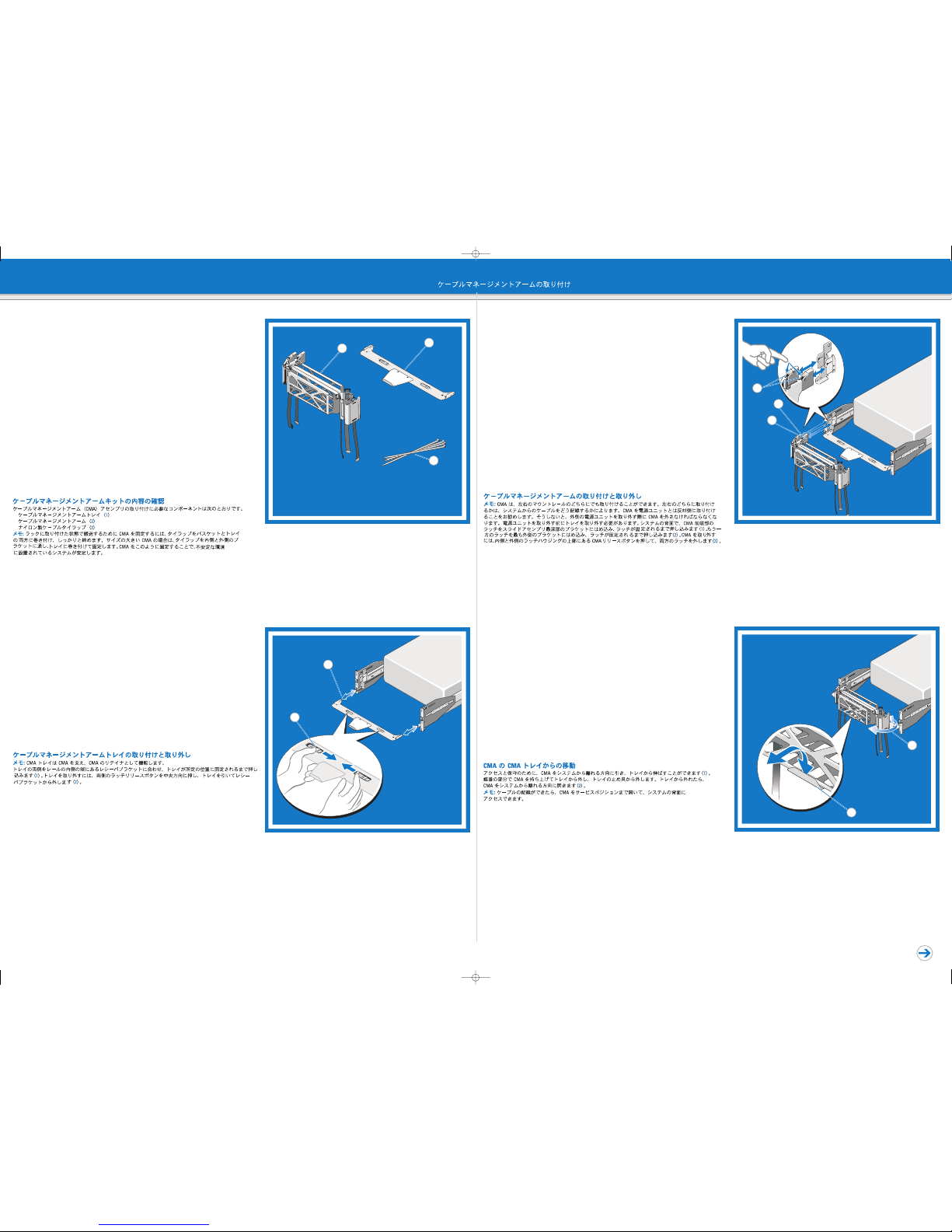
CMA Installation Instructions
Printed in China.
Imprimé en Chine.
Gedruckt in China.
Impreso en China.
Printed on recycled paper.
Instructions d'installation
du passe-câbles
Installationsanweisungen
für den Kabelführungsarm
Instrucciones de instalación
del brazo para tendido de cables
NNootteess,,CCaauuttiioonnssaannddWWaarrnniinnggss
A NNOOTTEE:indicates important information that helps you make better use of your computer.
A CCAAUUTTIIOONN:indicates potential damage to hardware or loss of data if instructions are not followed.
A WWAARRNNIINNGG:iinnddiiccaatteessaappootteennttiiaallffoorrpprrooppeerrttyyddaammaaggee,,ppeerrssoonnaalliinnjjuurryy,,oorrddeeaatthh..
RReemmaarrqquueess,,PPrrééccaauuttiioonnsseettAAvveerrttiisssseemmeennttss
Une RREEMMAARRQQUUEEindique des informations importantes qui peuvent vous aider à mieux utiliser
votre ordinateur.
Une PPRRÉÉCCAAUUTTIIOONNvous avertit d'un risque de dommage matériel ou de perte de données en cas
de non-respect des instructions données.
Un AAVVEERRTTIISSSSEEMMEENNTTvvoouussaavveerrttiittdd''uunnrriissqquueedd''eennddoommmmaaggeemmeennttdduummaattéérriieell,,ddeebblleessssuurreeccoorrppoorreellllee
oouuddeemmoorrtt..
AAnnmmeerrkkuunnggeenn,,VVoorrssiicchhttsshhiinnwweeiisseeuunnddWWaarrnnuunnggeenn
Eine AANNMMEERRKKUUNNGG:macht auf wichtige Informationen aufmerksam, mit denen Sie das System besser
einsetzen können.
Ein VVOORRSSIICCHHTTSSHHIINNWWEEIISS:warnt vor möglichen Beschädigungen der Hardware oder vor Datenverlust,
falls die Anweisungen nicht befolgt werden.
Eine WWAARRNNUUNNGG:wweeiissttaauuffGGeeffaahhrreennqquueelllleennhhiinn,,ddiieemmaatteerriieelllleeSScchhääddeenn,,VVeerrlleettzzuunnggeennooddeerrssooggaarr
ddeennTTooddvvoonnPPeerrssoonneennzzuurrFFoollggeehhaabbeennkköönnnneenn..
NNoottaass,,pprreeccaauucciioonneessyyaaddvveerrtteenncciiaass
Una NNOOTTAA:proporciona información importante que le ayudará a utilizar mejor el ordenador.
Un mensaje de PPRREECCAAUUCCIIÓÓNN:indica la posibilidad de daños en el hardware o la pérdida de datos
si no se siguen las instrucciones.
Un mensaje de AADDVVEERRTTEENNCCIIAA:iinnddiiccaaeellrriieessggooddeeddaaññoossmmaatteerriiaalleess,,lleessiioonneessooiinncclluussoollaammuueer
rttee..
WWAARRNNIINNGG::TThhiissiissaaccoonnddeennsseeddrreeffeerreennccee..RReeaaddtthheessaaffeettyyiinnssttrruuccttiioonnssiinnyyoouurr
Safety,
Environmental, and Regulatory Information
bbooookklleettbbeeffoorreeyyoouubbeeggiinn..
WWAARRNNIINNGG::OOnnllyyttrraaiinneeddsseerrvviicceetteecchhnniicciiaannssaarreeaauutthhoorriizzeeddttoorreemmoovveetthheessyysstteemmccoovveerraanndd
aacccceessssaannyyoofftthheeccoommppoonneennttssiinnssiiddeetthheessyysstteemm..BBeeffoorreeyyoouubbeeggiinn,,rreevviieewwtthheessaaffeettyy
iinnssttrruuccttiioonnsstthhaattccaammeewwiitthhtthheessyysstteemm..
NNOOTTEE::The illustrations in this document are not intended to represent a specific server. These
installation instructions show a 3U Cable Management Arm installation. Other CMAs may vary
slightly in appearance.
AAVVEERRTTIISSSSEEMMEENNTT::cceeddooccuummeenntteessttuunniiqquueemmeennttuunnccoonnddeennsséé..VVeeuuiilllleezzlliirreelleelliivvrreettrreellaattiiffàà
la sécurité, l'environnement et les réglementations
aavvaannttddeeccoommmmeenncceerr..
AAVVEERRTTIISSSSEEMMEENNTT::sseeuullsslleesstteecchhnniicciieennssddeemmaaiinntteennaanncceeqquuaalliiffiiééssssoonntthhaabbiilliittééssààrreettiirreerrlleeccaappoott
dduussyyssttèèmmeeppoouurraaccccééddeerraauuxxccoommppoossaannttssiinntteerrnneess..VVeeuuiilllleezzlliirreelleessccoonnssiiggnneessddeessééccuurriittéé
ffoouurrnniieessaavveecclleessyyssttèèmmeeaavvaannttddeeccoommmmeenncceerr..
RREEMMAARRQQUUEE::les illustrations figurant dans ce document ne représentent pas de serveur
spécifique. Ces instructions présentent l'installation d'un passe-câbles pour un système
à 3 unités. L'apparence des passe-câbles peut varier selon les modèles.
WWAARRNNUUNNGG::DDiieesseessDDookkuummeennttsstteelllltteeiinneeK
Kuurrzzaannlleeiittuunnggddaarr..BBeevvoorrSSiieemmiittddeerrMMoonnttaaggeebbeeggiinnnneenn,,
lleesseennSSiieebbiitttteeddiieeSSiicchheerrhheeiittsshhiinnwweeiisseeiinnddeer
rBBrroosscchhüürree
Sicherheits-, Umgebungs- und
Betriebsbestimmungen
..
WWAARRNNUUNNGG::NNuurrzzuuggeellaasssseenneeSSeerrvviicceetteecchhnniikkeerrddüürrffeennddiieeGGeehhääuusseeaabbddeecckkuunnggeennttffeerrnneenn
uunnddaauuffddiieeKKoommppoonneen
ntteenniimmIInnnneerrnnddeessSSyysstteemmsszzuuggrreeiiffeenn..BBeevvoorrSSiieebbeeggiinnnneenn,,lleesseennSSiiee
ddiieeSSiicchheerrhheeiittsshhiinnwweeiissee,,ddiieeSSiiee
zzuussaammmmeennmmiittIIhhrreemmSSyysstteemmeerrhhaalltteennhhaabbeenn..
AANNMMEERRKKUUNNGG::Die Abbildungen in diesem Dokument sollen keinen bestimmten Server darstellen.
Diese Anweisungen zeigen die Installation eines 3U-Kabelführungsarms. Andere Kabelführungs-
arme können im Erscheinungsbild leicht abweichen.
AADDVVEERRTTEENNCCIIAA::EEsstteeddooccuummeennttooeessuunnaarreeffeerreenncciiaarreessuummiiddaa..LLeeaallaassiinnssttrruucccciioonneessddeesseegguurriiddaadd
iinncclluuiiddaasseenneellffoolllleettoo
IInnffoorrmmaacciióónnssoobbrreesseegguurriiddaadd
,,mmeeddiiooaammbbiieenntteeyynnoorrmmaattiivvaassaanntteess
ddeeeemmppeezzaarr..
AADDVVEERRTTEENNCCIIAA::LLoossttééccnniiccoossddeesseerrvviicciiooeessppeecciiaalliizzaaddoossssoonnllaassúúnniiccaassppeerrssoonnaassaauuttoorriizzaaddaass
ppaarraarreettiirraarrllaassccuubbiieerrttaassyyaacccceeddeerraalloossccoommppoonneenntteessiinntteerrnnoossddeellssiisstteemmaa..AAnntteessddeeeemmppeezzaarr,,
rreevviisseellaassiinnssttrruucccciioonneessddeesseegguurriiddaaddiinncclluuiiddaassccoonneellssiisstteemmaa..
NNOOTTAA::Las ilustraciones de este documento no representan un servidor específico. En estas
instrucciones se muestra la instalación de un brazo para tendido de cables 3U. Es posible que
otros brazos para tendido de cables tengan un aspecto ligeramente diferente.
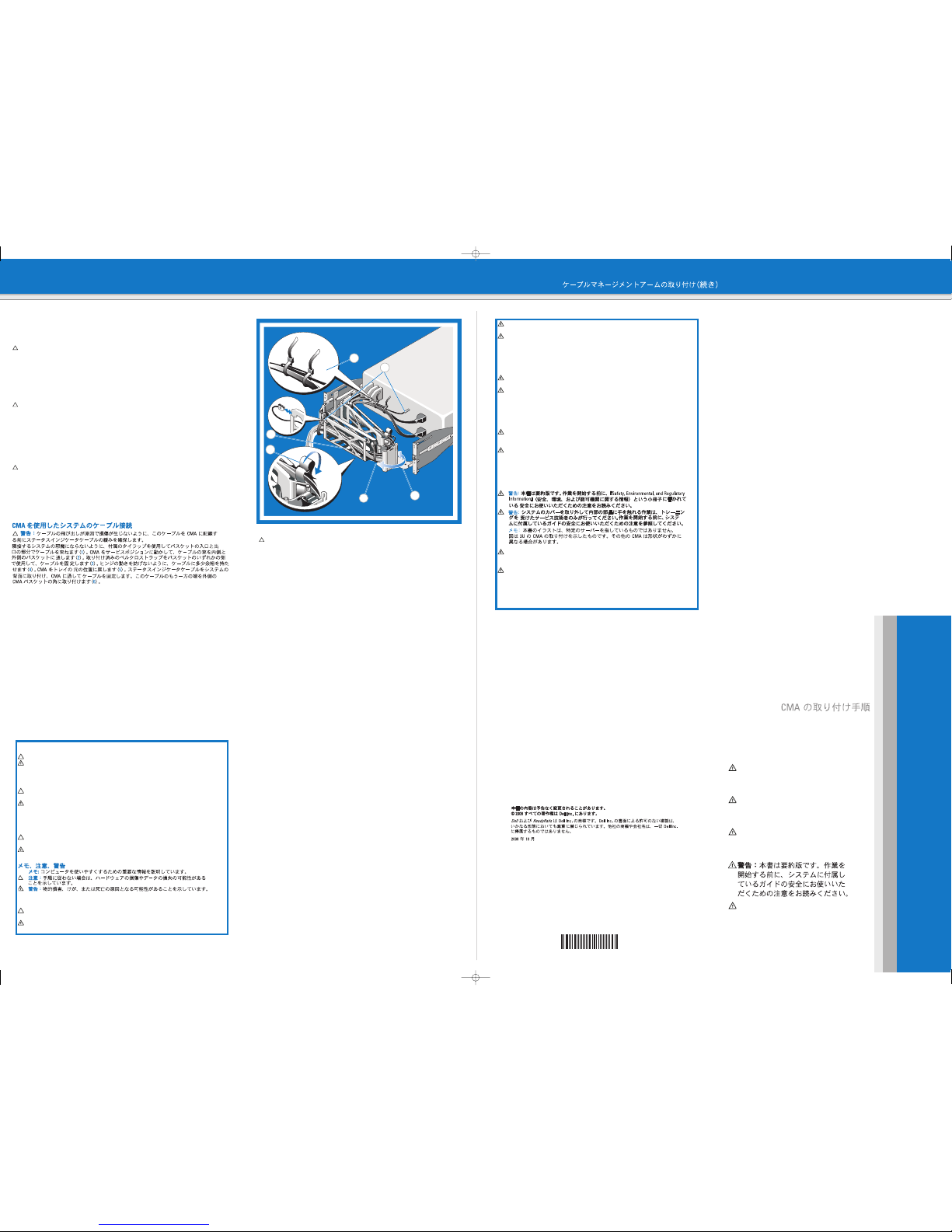
Cabling the System Using the CMA
CCAAUUTTIIOONN:To avoid potential damage from protruding cables, secure any slack in the status indicator cable
before routing this cable through the CMA.
Using the tie wraps provided, bundle the cables together as they enter and exit the baskets so they do not
interfere with adjacent systems (11). With the CMA in the service position, route the cable bundle through the inner
and outer baskets (22). Use the preinstalled Velcro straps on either end of the baskets to secure the cables (33).
Adjust the cable slack as needed at the hinge postion (44). Swing the CMA back into place on the tray (55). Install
the status indicator cable at the back of the system and secure the cable by routing it through the CMA. Attach
the other end of this cable to the corner of the outer CMA basket. (66).
Câblage du système à l'aide du passe-câbles
PPRRÉÉCCAAUUTTIIOONN:pour éviter tout dommage dû à des câbles dépassant du système, le câble du voyant d'état
ne doit pas présenter de mou avant son acheminement via le passe-câbles.
À l'aide des fixe-câbles, regroupez les câbles et faites-les passer dans les paniers afin qu'ils n'interfèrent pas
avec les systèmes adjacents (11). Mettez le passe-câbles en position de service, puis faites passer le faisceau
de câbles dans les paniers interne et externe (22). À l'aide des bandes Velcro préinstallées sur l'une ou l'autre
extrémité des paniers, fixez les câbles (33). Ajustez les câbles pour qu'il n'y ait pas de mou au niveau de la
charnière (44). Faites pivoter le passe-câbles pour le replacer dans le fixe-câbles (55). Installez le câble du voyant
d'état à l'arrière du système et sécurisez-le en le glissant dans le passe-câbles. Fixez l'autre extrémité de câble
au coin du panier externe du passe-câbles. (66).
Verkabeln des Systems mit dem Kabelführungsarm
VVOORRSSIICCHHTT:Um mögliche Schäden an vorstehenden Kabeln zu vermeiden, sichern Sie eine etwaige Überlänge
des Statusanzeigekabels, bevor Sie dieses Kabel im Kabelführungsarm verlegen.
Bündeln Sie mit den Kabelbindern die Kabel beim Eintritt und Austritt an den Kabeltunneln, so dass sie nicht mit
benachbarten Systemen in Konflikt geraten (11). Verlegen Sie Kabel durch den inneren und äußeren Kabeltunnel,
wobei sich der Kabelführungsarm in der Wartungsposition befindet (2). Sichern Sie die Kabel an den Enden
der Kabeltunnel mit den vorinstallierten Klettbändern (3). Passen Sie das Kabelspiel an der Scharnierposition
nach Bedarf an (4). Schwenken Sie den Kabelführungsarm zurück auf die Auflage (5). Installieren Sie das
Statusanzeigekabel auf der Systemrückseite und sichern Sie das Kabel, indem Sie es im Kabelführungsarm
verlegen. Befestigen Sie das andere Ende des Kabels an der Ecke des äußeren Kabelführungstunnels (66).
5
1
4
2
5
3
6
IInnffoorrmmaattiioonniinntthhiissddooccuummeennttiissssuubbjjeeccttttoocchhaannggeewwiitthhoouuttnnoottiiccee..
©©22000088DDeellllIInncc..AAllllrriigghhttssrreesseerrvveedd..
Dell
and
ReadyRails
are trademarks of Dell Inc. Reproduction in any manner whatsoever without the
written permission of Dell Inc. is strictly prohibited. Dell disclaims proprietary interest in the marks
and names of others.
October 2008
LLeessiinnffoorrmmaattiioonnssccoonntteennuueessddaannsscceeddooccuummeennttppeeuuvveennttêêttrreemmooddiiffiiééeessssaannsspprrééaavviiss..
©©22000088DDeellllIInnc
c..TToouussddrrooiittssrréésseerrvvééss..
Dell
et
ReadyRails
sont des marques de Dell Inc. La reproduction de ce document de quelque manière
que ce soit sans l'autorisation écrite de Dell Inc. est strictement interdite. Dell ne revendique aucun
droit propriétaire sur les marques et noms des autres sociétés.
Octobre 2008
DDiieeiinnddiieesseemmDDookkuummeenntteenntthhaalltteenneennIInnffoorrmmaattiioonneennkköönnnneennoohhnneeVVoorraannkküünnddiigguunnggggeeäännddeerrttwweerrddeenn..
©©2
2000088DDeellllIInncc..AAlllleeRReecchhtteevvoorrbbeehhaalltteenn..
Dell
und
ReadyRails
sind Marken von Dell Inc. Die Reproduktion dieses Dokuments in jeglicher Form ist
ohne vorherige schriftliche Genehmigung von Dell Inc. streng verboten. Dell erhebt keinen Anspruch
auf die Warenzeichen und Handelsnamen anderer Hersteller.
Oktober 2008
LLaaiinnffoorrmmaacciióónnccoonntteenniiddaaeenneesstteeddooccuummeennttooppuueeddeemmooddiiffiiccaarrsseessiinnnnoottiiffiiccaacciióónnpprreevviiaa..
©©22000088DDeel
lllIInncc..TTooddoosslloossddeerreecchhoossrreesseerrvvaaddooss..
Dell
y
ReadyRails
son marcas comerciales de Dell Inc. Queda estrictamente prohibida la reproducción
de este documento en cualquier forma sin la autorización por escrito de Dell Inc. Dell renuncia a
cualquier interés sobre la propiedad de marcas y nombres de terceros.
Octubre de 2008
WARNING: This is a condensed
reference. Read the safety instructions
that ship with your system before
you begin.
AVERTISSEMENT : ce document est
uniquement un condensé. Veuillez lire
les consignes de sécurité fournies
avec le système avant de commencer.
WARNUNG: Dieses Dokument stellt eine
Kurzanleitung dar. Bevor Sie beginnen,
lesen Sie die im Lieferumfang Ihres
Systems enthaltenen Sicherheitshinweise.
ADVERTENCIA: Este documento es
una referencia resumida. Lea las
instrucciones de seguridad suministradas
con el sistema antes de empezar.
Cable Management Arm Installation (continued) IInnssttaallllaattiioonndduuppaassssee--ccââbblleess((ssuuiittee))||IInnssttaallllaattiioonnddeessKKaabbeellffüühhrruunnggssaarrmmss((ffoorrttggeesseettzztt))||||IInnssttaallaacciióónnddeellbbrraazzooppaarraatteennddiiddooddeeccaabblleess((ccoonnttiinnuuaacciióónn))
Cableado del sistema mediante el brazo para tendido de cables
PPRREECCAAUUCCIIÓÓNN:Para evitar posibles daños debidos a cables que sobresalen, ajuste la holgura del
cable de indicador de estado antes de pasar este cable por el brazo para tendido de cables.
Mediante las abrazaderas proporcionadas, agrupe los cables al entrar y salir de los soportes de modo
que no interfieran con los sistemas adyacentes (11). Con el brazo para tendido de cables en la posición
de mantenimiento, pase el grupo de cables por los soportes interno y externo (22). Utilice las cintas de
velcro preinstaladas en cada extremo de los soportes para fijar los cables (33). Realice los ajustes de
holgura necesarios en los cables en las posiciones de las bisagras (44). Vuelva a girar el brazo para
tendido de cables para que encaje en la bandeja (55). Instale el cable de indicador de estado en la parte
posterior del sistema y fíjelo pasándolo por el brazo para tendido de cables. Fije el otro extremo de este
cable a la esquina del soporte externo del brazo para tendido de cables. (66).
F880Kcc0.qxp 30/10/2008 15:13 Page 2

Other manuals for PowerEdge T710

14

This manual suits for next models

5

Other Dell Server manuals

Dell PowerEdge T620 User manual

Dell

Dell PowerEdge T620 User manual

Dell DL4300 User manual

Dell

Dell DL4300 User manual

Dell External OEMR XL R210II Quick start guide

Dell

Dell External OEMR XL R210II Quick start guide

Dell PowerEdge T105 Systems User manual

Dell

Dell PowerEdge T105 Systems User manual

Dell POWEREDGE 4300 User manual

Dell

Dell POWEREDGE 4300 User manual

Dell PowerEdge 2450 Manual

Dell

Dell PowerEdge 2450 Manual

Dell Dimension 2200 User manual

Dell

Dell Dimension 2200 User manual

Dell OptiPlex FX130 User manual

Dell

Dell OptiPlex FX130 User manual

Dell PowerEdge 1950 Technical manual

Dell

Dell PowerEdge 1950 Technical manual

Dell PowerEdge R510 Quick start guide

Dell

Dell PowerEdge R510 Quick start guide

Dell PowerEdge M630 User manual

Dell

Dell PowerEdge M630 User manual

Dell PowerEdge PDU Managed LED User manual

Dell

Dell PowerEdge PDU Managed LED User manual

Dell PowerEdge C1100 User manual

Dell

Dell PowerEdge C1100 User manual

Dell POWEREDGE T300 User manual

Dell

Dell POWEREDGE T300 User manual

Dell PowerEdge T310 User manual

Dell

Dell PowerEdge T310 User manual

Dell POWEREDGE 4300 User manual

Dell

Dell POWEREDGE 4300 User manual

Dell PowerEdge M605 User manual

Dell

Dell PowerEdge M605 User manual

Dell PowerEdge C5230 User manual

Dell

Dell PowerEdge C5230 User manual

Dell 8 User manual

Dell

Dell 8 User manual

Dell PowerEdge R610 User manual

Dell

Dell PowerEdge R610 User manual

Dell PowerEdge M620 Quick start guide

Dell

Dell PowerEdge M620 Quick start guide

Dell PowerEdge FC830 User manual

Dell

Dell PowerEdge FC830 User manual

Dell Dimension 4100 User manual

Dell

Dell Dimension 4100 User manual

Dell PowerEdge R410 User manual

Dell

Dell PowerEdge R410 User manual

Popular Server manuals by other brands

Overland Storage SnapServer 110 Configuration and hardware options guide

Overland Storage

Overland Storage SnapServer 110 Configuration and hardware options guide

Neteon GW312 quick start guide

Neteon

Neteon GW312 quick start guide

UNIVIEW DVS4000 Series quick guide

UNIVIEW

UNIVIEW DVS4000 Series quick guide

Axis Camera Station S1216 Tower installation guide

Axis

Axis Camera Station S1216 Tower installation guide

Advantech ADAM-4571 user manual

Advantech

Advantech ADAM-4571 user manual

Canon imagePRESS A3200 Installation and service guide

Canon

Canon imagePRESS A3200 Installation and service guide

Siemens APOGEE Ethernet Microserver 2100 installation instructions

Siemens

Siemens APOGEE Ethernet Microserver 2100 installation instructions

Lenovo x3550 M4 Installation and service guide

Lenovo

Lenovo x3550 M4 Installation and service guide

Gigabyte R263-Z30-AAH1 user manual

Gigabyte

Gigabyte R263-Z30-AAH1 user manual

Fujitsu PRIMERGY BX920 S2 Options guide

Fujitsu

Fujitsu PRIMERGY BX920 S2 Options guide

Lenovo ThinkServer RD550 User guide and hardware maintenance manual

Lenovo

Lenovo ThinkServer RD550 User guide and hardware maintenance manual

Avaya Definity Enterprise Communications Server Operation manual

Avaya

Avaya Definity Enterprise Communications Server Operation manual

Supermicro SuperServer SYS-521AD-TN2 user manual

Supermicro

Supermicro SuperServer SYS-521AD-TN2 user manual

Lenovo ThinkServer TD200 Hardware Maintenance Manual

Lenovo

Lenovo ThinkServer TD200 Hardware Maintenance Manual

HP ML350 - ProLiant - G2 Quickspecs

HP

HP ML350 - ProLiant - G2 Quickspecs

Compaq ProLiant ML350 (G2) Service overview

Compaq

Compaq ProLiant ML350 (G2) Service overview

Huawei RH2488 V2 Server BMC user guide

Huawei

Huawei RH2488 V2 Server BMC user guide

HP ProLiant DL385p Generation 8 Quickspecs

HP

HP ProLiant DL385p Generation 8 Quickspecs

manuals.online logo
manuals.online logoBrands
  • About & Mission
  • Contact us
  • Privacy Policy
  • Terms and Conditions

Copyright 2025 Manuals.Online. All Rights Reserved.