dellonda DG98 User manual
Model No. DG98, DG99
Thank you for purchasing a Dellonda product. Manufactured to a high standard, this product will,
if used according to these instructions, and properly maintained, give you years of trouble free performance.
www.dellonda.co.uk
Dellonda Freestanding Gas Pyramid Patio Heater Outdoor
Garden Glass Tube 13kW
DG98 DG99 Issue:2 27/04/2021

2
Important Information
Please read these instructions carefully. Note the safe operational requirements, warnings & cautions. Use the product correctly and with care
for the purpose for which it is intended. Failure to do so may cause damage and/or personal injury and will invalidate the warranty. Keep these
instructions safe for future use.
Refer to
instruction
manual
Wear
Gloves
Specication label
About the Product
Innovative design of Gas Flame Pyramid Patio Heaters. These contemporary freestanding patio heaters produce a pleasant, heated working/
relaxing environment and are ideal for both commercial and domestic settings including open workshops, boat yards, patios, forecourts, gardens
and terraces. Standing at 2.27m tall, when lit the heaters produce a real ame encompassed by a glass tube which heats the surrounding area,
a metal reector makes sure heat is directed downwards and outwards. The units feature variable heat output controls and a fully enclosed gas
cylinder chamber with safety tip-over switch. Available in black or stainless steel and supplied with regulator and hose assembly for use with
propane patio gas bottles. These products should only be used in a well ventilated area.
Specication
Model ............................................................................DG98 .............................................................................................. DG99
Fuel Consumption:.....................................................945g/hr ........................................................................................... 945g/hr
Fuel:......................................................................... Propane ......................................................................................... Propane
Heated Area:....................................................................8m² ................................................................................................. 8m²
Output: ..........................................................................13kW .............................................................................................. 13kW
Product Dimensions (W x H):..........................520 x 2270mm ................................................................................520 x 2270mm
Maximum Gas Bottle Size (W x H):................Ø320 x 700mm ............................................................................... Ø320 x 700mm
Safety Instructions
• Read the installation, operating and maintenance instructions thoroughly before installing or using this equipment.
• If there is a smell of gas: shut off the gas to the appliance, extinguish any open ames. If odour continues contact gas supplier.
• DO NOT store or use petrol or other ammable substances inside the housing of the heater.
• DO NOT store or use petrol or other ammable liquids or gases in the vicinity of the heater.
• DO NOT store a gas cylinder that is not connected for use in the vicinity of this or any other appliance.
• WARNING! DO NOT use indoors. For use outdoors or in amply ventilated areas.
• An amply ventilated area is one that has a minimum of 25% of the surface area open, see g.1. (The surface area is the sum of the wall surface.)
• WARNING! Not intended to be installed in recreational vehicles and/or boats.
• WARNING! Improper installation, adjustment, alteration, service or maintenance can cause injury or property damage.
• Installation and repair must be carried out by a qualied person.
• DO NOT attempt to alter in any way.
• This product must be installed and the gas cylinder stored in accordance with the local regulations in force.
• DO NOT obstruct the ventilation holes of the cylinder housing.
• DO NOT move/transport the appliance when in operation. Shut off the gas cylinder at the regulator before moving.
• DO NOT move/transport the heater until it has cooled down.
• Use only the type of gas and the type of cylinder specied by the manufacturer.
• The LP cylinder used with the patio heater must meet the following size requirements: Diameter 31.8cm x height 58cm, 15kg maximum capacity.
• In case of violent wind precautions must be taken against tilting of the appliance.
• Only use on level ground, capable of supporting the weight of the heater and the gas cylinder.
• DO NOT connect the gas cylinder directly to the appliance without a regulator. Use only the type of gas specied in the instructions.
• The whole gas system (hose, regulator, pilot or burner) should be inspected for leaks or damage before use and at least annually, by a suitably
qualied person.
• All leak testing should be done with an appropriate gas leak detection/soap solution. Never use an open ame to check for leaks.
• DO NOT use the heater until all connections have been leak tested.
fig.1
3
• Turn off the gas immediately if a gas smell is detected. Turn cylinder valve OFF. If the leak is at the hose/regulator connection tighten the
connection and perform another leak test. If bubbles continue appearing contact your supplier. If the leak is at the regulator/cylinder connection
disconnect from cylinder, reconnect and perform another leak check. If soap bubbles are still seen, cylinder valve is defective. Return cylinder to
its place of purchase.
• Keep the ventilation opening of the cylinder enclosure free and clear of debris.
• DO NOT paint the radiant screen, control panel or top canopy reector.
• Control compartment, burner and circulation air passageways of the heater must be kept clean.
• Turn off gas whilst not in use.
• LP regulator/hose assembly must be a protected from accidental damage.
• Any guard removed for servicing/maintenance must be replaced before operation.
• Keeps adults and children away from the high temperature surfaces, to avoid burns and ignition of clothing.
• Children should be carefully supervised when they are in the vicinity of the heater.
• DO NOT hang clothing or other ammable materials on the heater or place them near the heater.
Heater Stand and Location
• The heater is primarily for outdoor use only. Always ensure that adequate fresh air ventilation is provided.
• Always maintain proper clearance to non protected combustible materials i.e. top 100 cm and sides 100 cm minimum.
• Heater must be placed on level rm ground.
• Never operate heater in an explosive atmosphere like in areas where gasoline or other ammable liquids or vapours are stored.
• To protect heater from strong wind, anchor the base securely to the ground with screws.
• Gas Requirements
• This heater is primarily designed to be used with propane gas.
• Butane gas may also be used with the appropriate regulator however butane freezes at zero degrees so will not be ideal to be used during cold
temperatures.
• A dented, rusted or damaged cylinder may be hazardous and should be checked by your gas supplier before being used with this heater.
• Never connect an unregulated cylinder to the heater.
Contents
(Model No. DG10001; 37mbar)

4
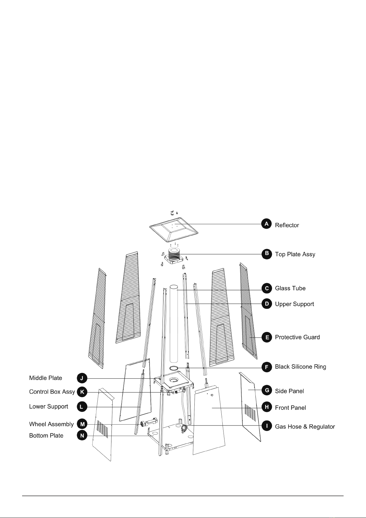
Assembly
• To assist connecting the regulator, carefully place the rubber hose into an insulated cup of boiling hot water. This allows the rubber hose to
expand and allow the regulator to be connected easily. After connecting the regulator, tighten the hose clip with a screwdriver.
• 1. Assemble the wheel assembly (M) to the bottom plate (N). Fix the wheel assembly (M) to the bottom plate (N) using 4pcs bolt M8x12 (EE) and
4pcs ange nut M8 (FF).
• 2. Insert the pins of the bottom plate (N) to the holes of lower support (L), press to secure the pins. Using 12pcs screw 3/16” (DD) to secure the
lower support (L) and bottom plate (N). Using 8pcs screw 3/16” (DD) to secure the lower support (L) and middle plate (J).
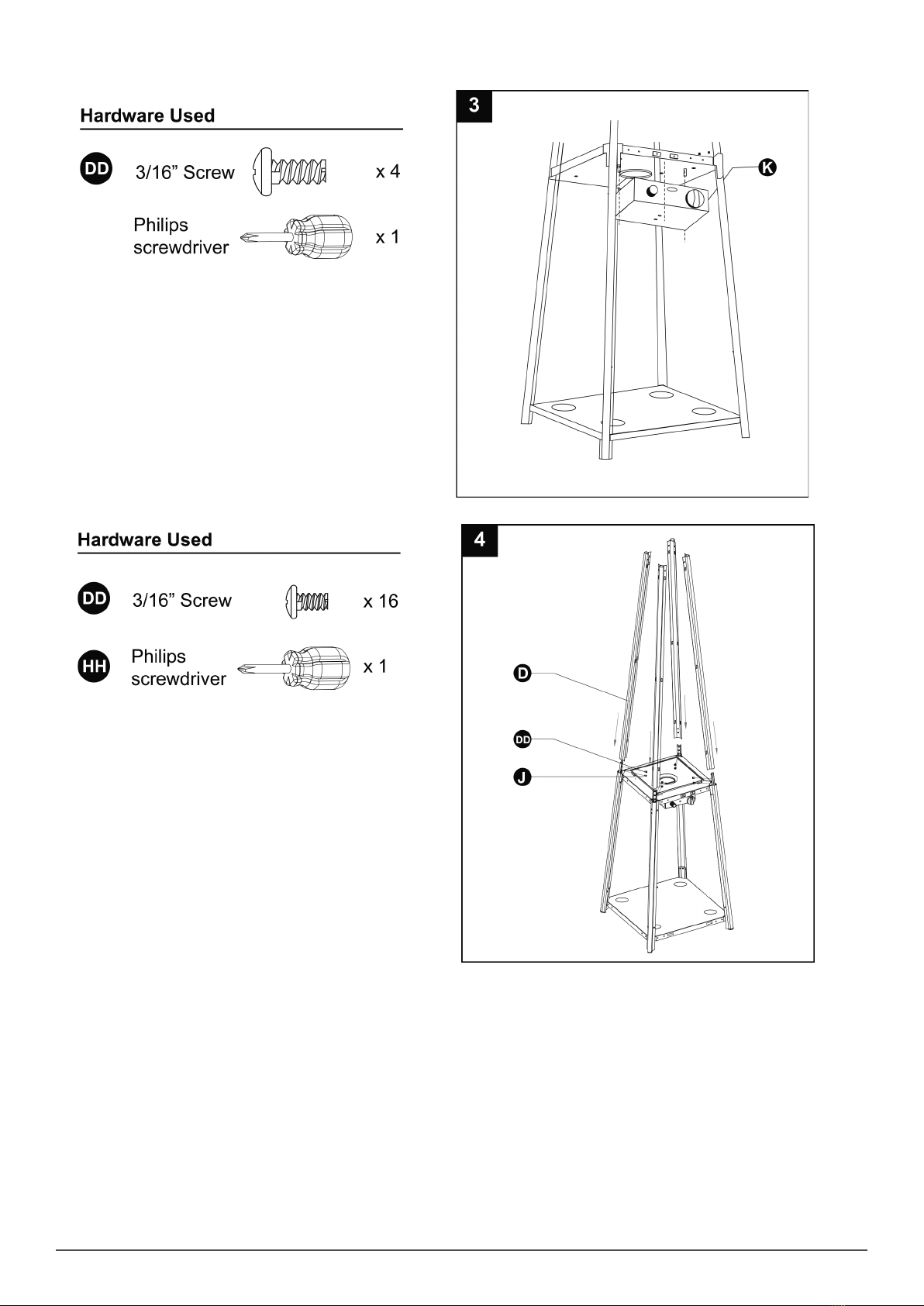
5
• 3. Assemble control box assy (K). Fix the Control Box Assy (K) to the Middle Plate (J), using 4pcs screw 3/16’ (DD)’.
• Additional Note : Unscrew the red ignition button and insert an AAA Battery
• 4. Assemble the upper support (D). Insert the 4pcs upper support (D) to the middle plate (J). Secure them with 16pcs screw 3/16” (DD)
This manual suits for next models
1
Table of contents
Other dellonda Patio Heater manuals


Popular Patio Heater manuals by other brands


OZONA
OZONA Heatflow IF010997 Safety instructions and operation manual

theBBQshop
theBBQshop 51611010 Safety, Installation, Operation and Maintenance

Matrix
Matrix PV009-200KB Safety instructions and operation manual

DCS
DCS PHFS-P4 Use and care and installation guide

Blumfeldt
Blumfeldt Hitzkopf manual

Nexgrill
Nexgrill 920-0049 Installation instructions and owner's manuals