RS-422/485 Multiport Serial PCI Card
1
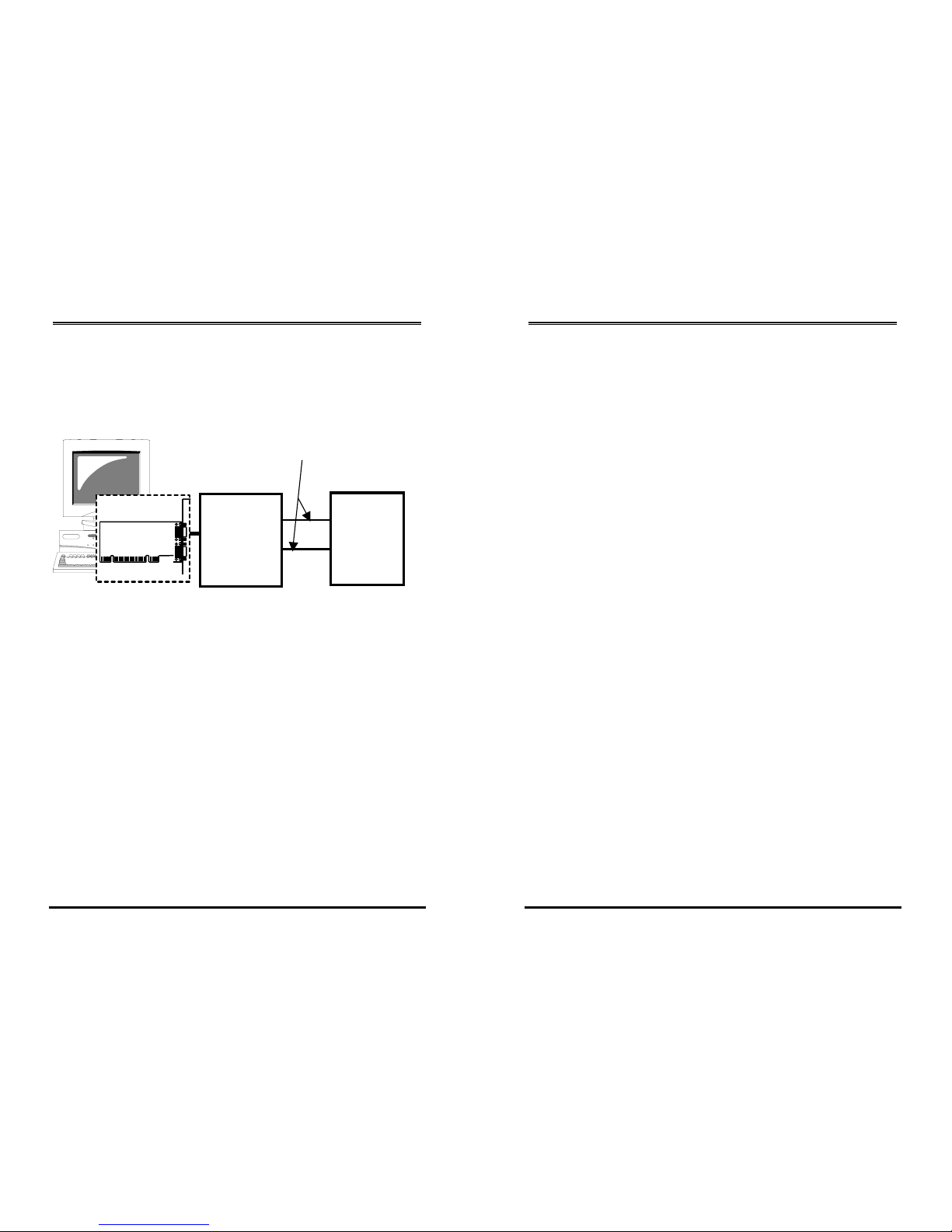
1. Introduction
Congratulation on your purchasing this high performance
RS-422/485 multiport serial PCI card. The card is high speed PCI
bus based and plug-and-play compliant. It works at 2-wire
(with Auto Transceiver Turn Around feature, ATTATM) and 4-wire
configuration. Its UARTs are fully 16C950 (128-byte FIFO)
featured and compatible with most of the serial devices
available from the market.
Features:
Fully PCI Bus Specifications 2.2 and Power Management 1.0
compliant
128-byte on-chip FIFO and arbitrary trigger levels and
interrupts, and automatic hardware/software flow control
Up to 921.6 Kbps baud rate, over 700 Kbps data throughput
5,6,7,8,9-bits data framing
Precise RS-485 ATTATM (Auto Transceiver Turn Around) feature
to disable the line driver by hardware
Supports echo mode to help software determining
unexpected bus collisions
Universal PCI compatible with 3.3/5V PCI and PCI-X buses
Optional 15KV ESD surge and optical isolation protection
models are available
Supports Win98/Me, NT, Windows 2000 and XP,2003, and
Linux
RS-422/485 Multiport Serial PCI Card
18
8.2 RS-422 (Transmitter buffer is always
enabled)
Please note that the RS-422/485 PCI Card supports 4-wire RS-422
mode. In this mode, the data was sent and received
independently. So you need to connect them with the
cross-over, twisted pair cable.
For the model with DB9 connectors, it also provides two
handshaking signials RTS+/RTS- and CTS+/CTS- to do the
hardware flow control. In this case, the wiring will be as follows:
RS-422/485 PCI Card
TXD+
TXD-
RXD+(485)
RXD-(485)
TX+
TX-
RX+
RX-
4-wire twisted pair cable
RS-422/485 PCI Card RS-422 Device
TXD+
TXD-
RXD+
RXD-
RTS+
RTS-
CTS+
CTS-
RS-422 Device
TXD+
TXD-
RXD+
RXD-
RTS+
RTS-
CTS+
CTS-