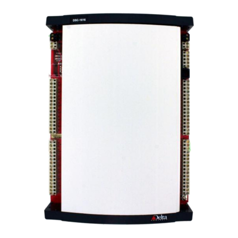
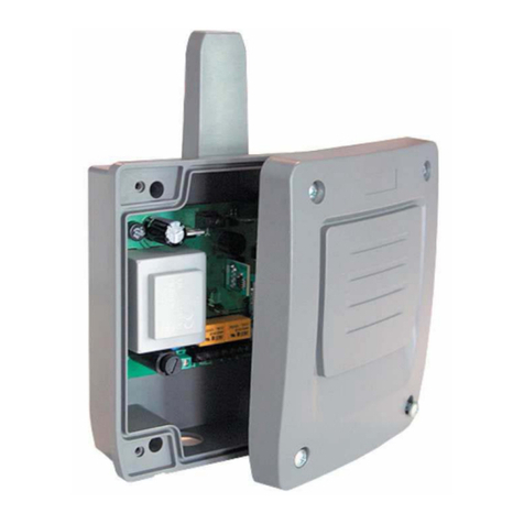
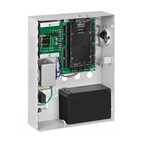
Delta Controls ADM-2W704 User guide

Delta Controls
Access Door Module Page 1 of 26
INSTALLATION & APPLICATION GUIDE
Access Door Module
ADM-2W704 (Rev 1.3)
Document Edition 1.2
PRODUCT DESCRIPTION
The Access Door Module is an intelligent device used
for access control of two single direction doors, or one
bi-directional door. It is used in conjunction with
Delta’s new generation of BACnet Controllers.
When connected to an Access System Manager on the
Delta LINKnet network, it provides programmable
remote door access control and expanded I/O
capabilities.
Access Door Modules can be networked together, to a
maximum of 12 Access Door Modules to provide
access control of up to 24 doors.
TABLE OF CONTENTS
PRODUCT DESCRIPTION ................................................................................................................................................... 1
TABLE OF CONTENTS ........................................................................................................................................................ 1
MODEL NUMBERS .............................................................................................................................................................. 2
UL AUTHORIZED ACCESSORIES ..................................................................................................................................... 2
OTHER ACCESSORIES FOR USE IN NON-UL APPLICATIONS..................................................................................... 2
PACKAGE CONTENTS ........................................................................................................................................................ 2
REQUIRED TOOLS............................................................................................................................................................... 2
OTHER RELEVANT DOCUMENTS.................................................................................................................................... 3
PRODUCT SPECIFICATIONS.............................................................................................................................................. 3
UL STANDARDS COMPLIANCE........................................................................................................................................ 5
BOARD LAYOUT (ACCESS DOOR MODULE)................................................................................................................. 6
INDICATORS......................................................................................................................................................................... 7
CONTROLLER ADDRESS DIP SWITCHES ....................................................................................................................... 7
MOUNTING........................................................................................................................................................................... 7
POWER WIRING................................................................................................................................................................... 8
BATTERY BACKUP WIRING (NOT TO BE CONNECTED IN UL APPLICATIONS) ....................................................8
INPUT WIRING................................................................................................................................................................... 11
OUTPUT WIRING............................................................................................................................................................... 20
LINKNET NETWORK & CABLING REQUIREMENTS................................................................................................... 22
NETWORK TOPOLOGY (CONFIGURATION NOT EVALUATED BY UL).................................................................. 23
COMMUNICATIONS SETUP............................................................................................................................................. 24
CAUTIONS AND WARNINGS........................................................................................................................................... 24
COMPLIANCE DECLARATIONS...................................................................................................................................... 25

Access Door Module ADM-2W704 (Rev 1.3) Installation & Application Guide
Page 2 of 26 Access Door Module
MODEL NUMBERS
Features ADM-2W704
Controller & Enclosure
UL AUTHORIZED ACCESSORIES
•AWID, Sentinel-Prox SR-2400 4 to 5.5 inch Read Range, Metal Compensated, Indoor
O
THER
A
CCESSORIES FOR USE IN NON
-UL
APPLICATIONS
•R10 - 6100 HID iClass Mullion Indoor/Outdoor Smart Card Reader up to 3½”
•R30 - 6110 HID iClass European/Asian Indoor/Outdoor Smart Card Reader up to 4”
•R40 - 6120 HID iClass Single Gang Indoor/Outdoor Smart Card Reader up to 4¼”
•200X iClass Card HID Smart Card for Direct Image & Thermal Transfer
•206X iClass Tag HID Smart Card as Tag with Adhesive Back
•205X iClass Key HID Smart Card in molded plastic key fob
•Sentinel-Prox HP-6840 6 to 8 inch Read Range, Single Gang Box Mount
•Sentinel-Prox SR-2400 4 to 5.5 inch Read Range, Metal Compensated, Indoor/Outdoor
•Sentinel-Prox MM-6800 6 to 8 inch Read Range, Metal Compensated, Indoor/Outdoor
•Sentinel-Prox SP-6820 6 to 8 inch Read Range, Single Gang Box Mount
•Sentinel-Prox MR-1824 18 to 24 inch Read Range, Dimensions Only 8”x 8” x 1”, Indoor/Outdoor
•Sentinel-Prox MR-1824 MC Metal Compensated Version
•Prox-Line – GR Graphics Quality, both sides, ISO Compliant
•Prox-Line – CS “Clam Shell” style Prox Badge, Pre-Punched in Portrait Orientation
•Prox-Line – KT Proximity Key Tag (Key Fob)
P
ACKAGE
C
ONTENTS
•Access Door Module Board, ADM-2W704 (Rev 1.3)
•Stylized Enclosure for quick mounting
•Access Door Module ADM-2W704 (Rev 1.3) Installation & Application Guide
•Package containing 8-10K Resistors for EOL resistors and 1 pre-wired Battery Connector
R
EQUIRED
T
OOLS
•Terminal flat head screwdriver
•Wire cutters and strippers
•Screws and screw driver for mounting controller

Delta Controls
Access Door Module Page 3 of 26
OTHER RELEVANT DOCUMENTS
•Access Control System Technical Reference Manual
•Access Control System V3.30 Release Notes
•RS-485 Network Installation Guide (DOC818-11)
•ORCAview Operator Guide
•V3.30 ORCAview Technical Reference Manual
•V3.30 Release Notes
•Delta Controls System Description
P
RODUCT
S
PECIFICATIONS
Power Requirements
•24 VAC, 50/60Hz, 75 VA (dedicated transformer) Class 2 Device
•4A Slow Blow Fuse for controller and device power
•7.0 AH Lead Acid Battery Connection (for battery charging and battery back-up of the controller, as
well as all devices connected and powered from the controller)
•DC Power out +14 VDC @ 0.25A with a resetable fuse (can supply one Access System Manager
with battery backup)
•Card reader power +5 VDC @ 50mA or +12 VDC @ 160mA for each card reader individually fused
with a resetable fuse
•Door Lock power +12 VDC @ 350mA for each lock individually fused with a resetable fuse
•Auxiliary DC Power out +12 VDC @ 50mA fused with a resetable fuse
Ambient Ratings
•32º to 131º F (0º to 55º C)
•10 to 90% RH (non-condensing)
Communication Ports
NET1 - Main LAN (LINKnet)
•Communications Speed @ 76,800 BPS
•Maximum one Access Door Modules per Access System Manager (ASM)
•Visual LED status of network activity

Access Door Module ADM-2W704 (Rev 1.3) Installation & Application Guide
Page 4 of 26 Access Door Module
Inputs
•2 Wiegand Devices
•5 Type 1,2,3,4 EOL Supervised Inputs
o2 Door Contacts
o2 Auxiliary Inputs (i.e. tamper from card reader, motion detector, etc)
o1 Tamper Input for cabinet
•2 Request to Exit Inputs (internally wired to door strike output to reduce field wiring)
•9 Internal Inputs for controller status
o2 Door Strike/Magnetic Lock Power Status
o1 Auxiliary Power Status
o1 AC Power Status
o1 Battery Status
o2 Door +5 VDC Power Status
o2 Door +12 VDC Power Status
Outputs
•2 Door Locks, Form C Relay (rated 24VDC/AC @ 5A) with MOV protection, internally supplied
with +12 VDC as above.
•2 Auxiliary Relays, Form C Relay 24VDC/AC @ 5A with MOV protection (N.O. and N.C. contacts
available)
•4 LED Outputs for control of LEDs on Card readers. Open-collector current sink maximum 24VDC
@50mA current limited (LED or Buzzer output)
Technology
•8 bit Processor c/w internal A/D, Flash, and RAM
Device Addressing
•Set via DIP switch for LINKnet Address (0 to 12 per LINKnet segment)
Size
Controller & Enclosure
•8” x 9.5” x 2.5” (20.3 cm x 24.1 cm x 6.4 cm)
Weight (c/w Enclosure)
•Controller & Enclosure = 1.2 lb. (547 g.)

Delta Controls
Access Door Module Page 5 of 26
UL STANDARDS COMPLIANCE
This system has been tested by Underwriters Laboratories, Inc. for UL Indoor requirements per Standard UL
294, Access Control System Units. It has been tested for compliance with Listed Proximity Card Reader
Sentinel-Prox SR-2400 only.
The only configuration evaluated by UL is a system containing one ASM-24E, one ADM-2W704, an UL
Listed Transformer Basic Electric Industrial Cat. No. 7511 CBDH, ENC761 enclosure, and Applied Wireless
Listed Proximity Card Reader, Sentinel-Prox SR-2400. The system employs Wiegand 26 communication
protocol and was verified in the evaluation.
UL has not evaluated the following features of the ADM-2W704 and therefore should not to be connected in
UL applications: Battery Backup, Auxiliary Power, Request to Exit, or Auxiliary Relay Outputs. Any items not
evaluated by UL shall not be connected to the system in UL applications or installations.
All Read Ranges specified in this Manual are nominal and are dependent upon environmental and credential
electrical parameters and have not been evaluated by UL.
Product has been evaluated for the following levels in accordance with UL294 6th Edition:
•Destructive Attack – Level I
•Line Security – Level I
•Endurance – Level IV
•Standby Power – Level I
•Battery capacity for loss of primary power 0 hours

Access Door Module ADM-2W704 (Rev 1.3) Installation & Application Guide
Page 6 of 26 Access Door Module
BOARD LAYOUT (ACCESS DOOR MODULE)
All Terminal Class 2

Delta Controls
Access Door Module Page 7 of 26
INDICATORS
LED Function Description
AC PWR OK AC Power Indicator This green LED is on when the 24 VAC Power is
present on the device. If no 24 VAC Power
transformer is connected or the fuse (F1) is blown,
the LED will be off.
Network
(NET1) RS-485 Communication Status
Indicators for NET1 (LINKnet) Green LEDs flash to indicate when the device is
transmitting data through the associated port, and
red LEDs flash to indicate when the device is
receiving data through the port.
Outputs
(OP1 – OP9) Each green Output LED displays the
status of its corresponding output The green LED is on or off to match the binary
status of the associated output.
CONTROLLER ADDRESS DIP SWITCHES
Each individual DIP switch represents a pre-defined value (as printed on PCB beside the address block),
which added together forms the device address. LINKnet device addresses must be between 1 and 12 for the
device to communicate with its’ master device. Each LINKnet device must have a unique device address in
this range.
M
OUNTING
The Access Door Module is designed for quick and easy mounting in a number of locations. Normally this
should be within a secured enclosure.
A tamper switch should always be wired to the Access Door Module, indicating when someone enters the
enclosure and tampers with the Access Door Module. Any standard switch that will mount inside the
enclosure can be used. The tamper switch can be wired so that the circuit is monitored using an EOL circuit
(see Input Wiring below for details).

Access Door Module ADM-2W704 (Rev 1.3) Installation & Application Guide
Page 8 of 26 Access Door Module
POWER WIRING
All power wiring must be completed by a licensed electrician and conform to the National Electrical Code,
ANSI/NFPA 70, and local codes and regulations.
The Access Door Module must be powered by the UL listed, 24VAC, 50/60 Hz Basic Electric transformer,
Model 7511CBDH, or equivalent. Connect low voltage power (24VAC) from the UL listed transformer to the
AC power terminals, marked as 24~.
•The Access Door Module needs to use its own dedicated transformer as its 24 VAC
power source. You may not connect several controllers to the same transformer.
•Use 14 AWG minimum for wiring the AC in (i.e.120VAC) side of the UL listed
transformer, per NEC requirements.
•Keep adequate spacings between battery, power limited field wiring and AC in.
Suggest using UL recognized cable ties. Minimum .25” separation must be provided.
•Use proper strain relief for any flexible wiring.
•Use bushings on rough surfaces to protect cabling from abrasion.
•Do not wire power cord behind electrical enclosure.
•All terminals are acceptable for Class 2 Circuit connections only
•Use copper conductors only
•Apply minimum 6.0 lb-in torque for tightening field wires into the terminal blocks
BATTERY BACKUP WIRING (NOT TO BE CONNECTED IN UL APPLICATIONS)
The Access Door Module has been designed with a battery circuit to provide the option of both battery
charging and battery backup for the controller. The battery backup supplies power to the controller, its
output devices (if power from the board), and Auxiliary power connections. Battery backup should be used
when using Magnetic Locks on any doors that you would like to keep locked when there is a power failure or
having the Access Control System be functional in the event of a power loss.
The battery charging circuit has been designed for the following battery specifications:
•7 Amp Hours
•Sealed Lead Acid battery only
•Capable of both a trickle charge and bulk charge
•Use supplied 0.25” Faston Lugs for connecting battery
Using a 7 AH Battery, the table below shows approximately how long the battery will last when fully
charged. (Not evaluated by UL)
Lock Duty (Battery Full Charge) Battery Back-up Time (hours)
No lock activity, with Access System Manager backed-up
8
50% duty lock activity, with Access System Manager backed-up
5
100% duty lock activity, with Access System Manager backed-up
4
No lock activity
12
50% duty lock activity
6
100% duty lock activity
4
Note: Battery back-up times are approximations based on loads specified with a new battery. Old
batteries will not perform as well due to normal battery degradation.

Delta Controls
Access Door Module Page 9 of 26
24 VAC Access Door Module Power Connection Wiring Detail
Battery Connection Wiring Detail (Not evaluated by UL)

Access Door Module ADM-2W704 (Rev 1.3) Installation & Application Guide
Page 10 of 26 Access Door Module
DC Power Out Used Power and Battery Backup Access System Manager
Auxiliary Power Wiring (Not Evaluated by UL)

Delta Controls
Access Door Module Page 11 of 26
INPUT WIRING
There are 2 input types on the Access Door Module:
•Wiegand Inputs
•Regular Contact/Resistive Inputs (supplied with 10 – 10K ¼ Watt resistors for EOL circuits)
Wiegand Inputs are for card readers, keypads, biometric devices, etc, using the standard Wiegand Input signals
on WD0 and WD1. See table below for input assignment and numbering.
Regular inputs are resistive 10K Ohm pull-up inputs and are used for Door Contact, Request to Exit, etc.
Inputs follow the same general wiring connection diagrams as other Delta products, with the exception that you
can use EOL circuits to monitor the input wiring for open or short circuits. When EOL circuits are in place the
input must be created as a Multistate Input (MI) with the proper Multistate Input Configuration (MIC) for the
scale range. For details on the MIC scale range refer to the Technical Reference Manual. See below for
wiring details when using EOL circuits.
The Request to Exit input is configured based on the type of Door Lock that you are going to use. Placing a
jumper in the proper terminals on the board configures the Request to Exit input. Product is shipped
configured as a Fail Secure door. See diagram below.
The tamper switch input is connected to a standard single contact switch such as the Locknetics Security
Model 7766 (either the N.O. or N.C. action can be set-up in the input object) to monitor intrusion of the Access
Door Module’s enclosure.
Input Table
Input
Door
Function
Wiegand Reader A Wiegand Device input
Wiegand Reader
B
Wiegand Device input
BI1/MI1
A
Door Contact
BI2/MI2
A
Request to Exit Status
AI3/BI3/MI3 A Auxiliary Input (Not to be used in UL applications)
BI4
A
Door Strike/Magnetic Lock Power Status (Software input)
BI5/MI5
B
Door Contact
BI6/MI6
B
Request to Exit Status
AI7/BI7/MI7 B Auxiliary Input (Not to be used in UL applications)
BI8
B
Door Strike/Magnetic Lock Power Status (Software input)
AI9/BI9/MI9
N/A
Tamper Switch – can be used as an auxiliary input if not used
BI10
N/A
Auxiliary Power Status (On power Ok)
BI11 N/A AC Power Status (On AC Power Ok)
BI12
N/A
Battery Status (On Battery Ok)
BI13
A
+5 VDC Card reader Power Status (On +5 VDC Power Ok)
BI14
A
+12 VDC Card reader Power Status (On +12 VDC Power Ok)
BI15 B +5 VDC Card reader Power Status (On +5 VDC Power Ok)
BI16
B
+12 VDC Card reader Power Status (On +12 VDC Power Ok)
Note: Inputs in Italics are not physical inputs. They are internal inputs on the Access Door Module that report
the status of the Access Door Module.

Access Door Module ADM-2W704 (Rev 1.3) Installation & Application Guide
Page 12 of 26 Access Door Module
Wiegand Device Wiring (examples using HID and AWID card readers)
Wiegand Device wiring details are shown below. The +5 VDC power for card readers is from a switched
power supply and is used with Wiegand magnetic stripe readers, etc. It is recommended, when using proximity
card readers, that you should use the +12 VDC power supplied by the board for maximum read distance. The
Access Door Module +12 VDC is a linear power supply (which is required by most proximity card reader
manufacturers).
You should follow the wiring and wire type specifications of the card reader manufacturer that you are using.
Below is the typical wire type and distance specified by most card reader manufacturers; these are the
specifications for the card readers supplied by Delta Controls Inc. Card readers should always be grounded
properly to ensure proper operation (refer to the manufacturers installation data).
Wire Size #22 AWG (0.6mm Dia.) #18 AWG (1.2mm Dia.)
Wiegand Reader 500 ft (152 meters)
980 ft (300 meters)
RS-232 45 ft (15 meters) 45 ft (15 meters)
HID iCLASS Rxx Smart Card Reader Wiring

Delta Controls
Access Door Module Page 13 of 26
AWID/HID Prox Card Reader Wiring

Access Door Module ADM-2W704 (Rev 1.3) Installation & Application Guide
Page 14 of 26 Access Door Module
Request to Exit Input (Not Evaluated by UL)
The Request to Exit input has 2 components; the first is the Request to Exit Status that is monitored by
software, to give the operator the status of the button. The second component is the contact on the Request to
Exit button that interrupts the Door Lock signal to allow egress. The Request to Exit push button must have
both an N.O. contact and an N.C. contact to retrieve the status and to interrupt the Door Lock for egress. The
table and diagram below show how the Request to Exit should be configured and wired for the Door Lock type
chosen.
When using a Type 3 or Type 4 EOL Circuit and a Request to Exit button that has a single pole switch, make
sure that the 10K Ohm resistor is on the input leg of the circuit, not the ground side of the circuit, or the Door
Lock and/or Request to Exit status may not work properly, as shown below. Optional EOL Circuit resistors
are shown for EOL Circuit Types 3 and 4.
RTE Configuration and Wiring
The product is shipped configured for Fail Secure doors.
Door Lock RTE Status RTE Contact Jumper
Fail Safe N.O. N.C. 2-3
Fail Secure N.C. N.O. 1-2

Delta Controls
Access Door Module Page 15 of 26
If no RTE is being used, you must configure the circuit. If the Door Lock is configured as fail-safe, a jumper
needs to be put in place of the RTE Contact. The diagram below shows how the RTE circuit is configured
when not using an RTE device.
Note: Fail secure only allowed where NFPA 101or local authorities allow.

Access Door Module ADM-2W704 (Rev 1.3) Installation & Application Guide
Page 16 of 26 Access Door Module
No RTE Configuration and Wiring
Door Lock RTE Status RTE Contact Lock Configure
Jumper
Fail Safe N.O. N.C. 2-3 4-5
Fail Secure N.C. N.O. 1-2 N/A
EOL Circuits
Any of the inputs, other than the Wiegand Inputs, can be wired to be monitored/supervised circuits able to
detect problems or tampering with wiring. The 4 types, Type 1,2,3, and 4, of monitored circuits that Delta
Controls supports are described with the diagrams below. Each EOL circuit is based on 10K Ohm (±5%)
resistors. EOL resistors should be installed at the end of the line (at the device), not at the Access Door Module
(controller). Placing an EOL at the Access Door Module renders the circuit unmonitored, as it will only
monitor to the point of the controller connection.
Delta Controls recommends using EOL Types 3 & 4 if input wiring is to be monitored as they
provided the most information regarding the condition of the input circuit (wiring).
Scale Ranges (MIC objects) have been provided with the release CD-ROM, that should be used for these types
of inputs. You must use the MIC Objects provided as the software controlling Door Locks for the values in
pre-defined spots.

Delta Controls
Access Door Module Page 17 of 26
Type 1 EOL Circuit (Normally Closed Contact)
Used to monitor a Normally Closed contact, this EOL supervised circuit will give you a Trouble signal, in
addition to the Normal and Alarm signals, to let you know if the circuit has been shorted (contact bypassed). It
does not give Trouble indication of an Open circuit (wires cut), but it will cause an alarm condition.
Type 2 EOL Circuit (Normally Open Contact)
This EOL Circuit is used to monitor/supervise a Normally Open contact, to indicate Trouble when there is an
Open Circuit (wires cut). A short circuit (contact bypassed) will not indicate Trouble, but will generate an
Alarm condition.
Contact Door Contact Voltage Range
Type 1 - Normally Closed Contact
Switch Closed
Switch Open
Circuit Shorted
Door Open
Door Closed
Trouble
1.17 - 3.62
3.63 - 5.00
0.00 - 1.16
10
KOhm
N.C.
21
Input
Request to Exit
Door Close
Request to Exit
Trouble
Contact Door Contact Voltage Range
Type 2 - Normally Open Contact
Switch Closed
Switch Open
Circuit Open
Door Closed
Door Open
Trouble
0.00 - 1.16
1.17 - 3.62
3.63 - 5.00
10
KOhm
2
1
Input
N.O.
Request to Exit
Request to Exit
Door Close
Trouble

Access Door Module ADM-2W704 (Rev 1.3) Installation & Application Guide
Page 18 of 26 Access Door Module
Type 3 EOL Circuit (Normally Closed Contact)
This EOL Circuit is used to monitor/supervise a Normally Closed contact, to indicate Trouble when there is
either a Short Circuit (contact bypassed) or Open Circuit (wires cut). This supervised circuit gives the most
feedback on the input’s condition, along with Type 4 for Normally Open contacts.
When using a Type 3 or Type 4 EOL Circuit and a Request to Exit button that has a single pole switch, make
sure that the 10K Ohm resistor is on the input leg of the circuit, not the ground side of the circuit, or the Door
Lock and/or Request to Exit status may not work properly, as shown below.
Contact Door Contact Voltage Range
Type 3 - Normally Closed Contact
Switch Closed
Switch Open
Circuit Open
Circuit Short
Door Open
Door Closed
Trouble (open)
Trouble (shorted)
1.17 - 2.89
2.90 - 4.02
4.03 - 5.00
0.00 - 1.16
10
KOhm
21
Input
10
KOhm
N.C.
Request to Exit
Door Close
Request to Exit
Trouble (open)
Trouble (shorted)

Delta Controls
Access Door Module Page 19 of 26
Type 4 EOL Circuit (Normally Open Contact)
This EOL Circuit is used to monitor/supervise a Normally Open contact, to indicate Trouble when there is
either a Short Circuit (contact bypassed) or an Open Circuit (wires cut). This supervised circuit gives the most
feedback on the input’s condition, along with Type 3 for Normally Closed contacts.
When using the Type 3 or Type 4 EOL Circuit and a Request to Exit button that has a single pole switch, make
sure that the 10K Ohm resistor is on the input leg of the circuit, not the ground side of the circuit, or the Door
Lock and/or Request to Exit status may not work properly, as shown below.
Contact Door Contact Voltage Range
Type 4 - Normally Open Contact
Switch Closed
Switch Open
Cicuit Open
Circuit Short
Door Closed
Door Open
Trouble (open)
Trouble (shorted)
1.17 - 2.89
2.90 - 4.02
4.02 - 5.00
0.00 - 1.16
10
KOhm
21
Input
10
KOhm
N.O.
Request to Exit
Request to Exit
Door Close
Trouble (open)
Trouble (shorted)

Access Door Module ADM-2W704 (Rev 1.3) Installation & Application Guide
Page 20 of 26 Access Door Module
OUTPUT WIRING
The Outputs on the Access Door Module, like the inputs, are not general outputs. They typically have specific
operations. There is an auxiliary output for each door on the board that gives you an SPDT relay output.
Outputs on the Access Door Module follow the same general wiring connection diagrams as other Delta
products. Refer to separate documentation for additional details regarding this wiring.
Output Table
Output Door Function
BO1 A Door Strike
BO2 A Auxiliary Relay Output (SPDT) (Not to be connected in UL applications)
BO3 A LED1
BO4 A LED2
BO5 B Door Strike
BO6 B Auxiliary Relay Output (SPDT) (Not to be connected in UL applications)
BO7 B LED1
BO8 B LED2
BO9 N/A Trouble LED
Door Lock Wiring Detail
The Door Lock output is wired straight back to the Access Door Module as shown below. The Access Door
Module supplies +12VDC @ 350 mA maximum for powering the Door Lock. Therefore only +12VDC Door
Locks can be wired directly to the board, as shown below. If the Door Lock draws more than 350mA, then the
Door Lock should be wired as shown in the following diagram.
If a voltage other than +12VDC or an AC voltage is needed for the Door Lock, a DC Relay and a separate
power supply to control the Door Lock is needed, see wiring detail below. This wiring configuration can also
be used when the Door Lock draws more than 500mA.
WARNING
When a Door Lock is connected this way, the Door Lock will not be battery backed-up by the
board, but needs to be battery backed-up from it’s own source.
Table of contents
Other Delta Controls IP Access Controllers manuals
