Delta Controls ASM-24 User guide

Access System Manager Page 1 of 18
INSTALLATION & APPLICATION GUIDE
Access System Manager
ASM-24 (Rev 1.2)
Document Edition 1.1
PRODUCT DESCRIPTION
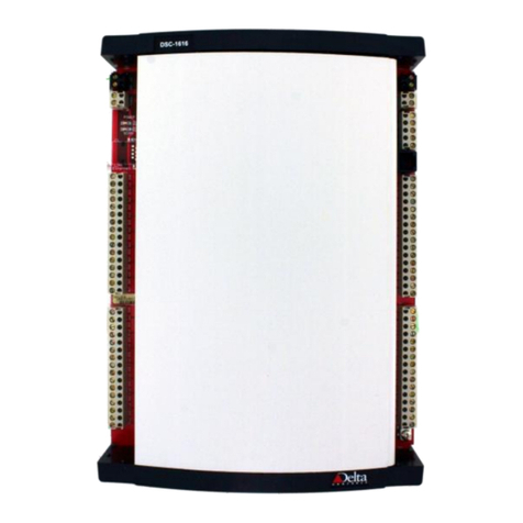
The Access System Manager is a Native BACnet
Controller that communicates on a BACnet MS/TP or
Ethernet LAN using the BACnet protocol.
The Access System Manager is an intelligent
controller specifically designed for access control
applications. While this controller has no I/O it
provides access control capabilities through a network
of Door Modules which act as extended I/O to the
Access System Manager.
TABLE OF CONTENTS
PRODUCT DESCRIPTION.................................................................................................................................1
MODEL NUMBERS............................................................................................................................................2
ACCESSORIES....................................................................................................................................................2
PACKAGE CONTENTS......................................................................................................................................2
REQUIRED TOOLS.............................................................................................................................................2
OTHER RELEVANT DOCUMENTS..................................................................................................................2
PRODUCT SPECIFICATIONS ...........................................................................................................................3
BOARD LAYOUT (ACCESS SYSTEM MANAGER).......................................................................................5
INDICATORS ......................................................................................................................................................6
JUMPER CONFIGURATION..............................................................................................................................7
CONTROLLER ADDRESS DIP SWITCHES.....................................................................................................8
MOUNTING.........................................................................................................................................................8
POWER WIRING.................................................................................................................................................8
NETWORK TOPOLOGY..................................................................................................................................10
SERIAL (RS232) NETWORKS & CABLING REQUIREMENTS...................................................................11
MODEM (RS232) NETWORKS & CABLING REQUIREMENTS .................................................................12
ETHERNET NETWORKS & CABLING REQUIREMENTS...........................................................................13
LINKNET AND MS/TP NETWORKS & CABLING REQUIREMENTS........................................................15
COMMUNICATIONS SETUP ..........................................................................................................................16
CAUTIONS AND WARNINGS ........................................................................................................................16
COMPLIANCE DECLARATIONS...................................................................................................................17

Access System Manager ASM-24 (Rev 1.2) Installation & Application Guide
Page 2 of 18 Access System Manager
MODEL NUMBERS
Features ASM-24 ASM-24E
Controller & Enclosure !!
Communicates on MS/TP LAN !!
Communicates on Ethernet !
ACCESSORIES
•ADM-2W704 Delta Controls, Access Door Module
PACKAGE CONTENTS
•Access System Manager Board, ASM-24 (Rev 1.2)
•Stylized Enclosure for quick mounting
•Access System Manager ASM-24 (Rev 1.2) Installation & Application Guide
REQUIRED TOOLS
•Terminal flat head screwdriver
•Wire cutters and strippers
•Screws and screw driver for mounting controller
OTHER RELEVANT DOCUMENTS
•Access Control System Technical Reference Manual
•Access Control System V3.22 Release Notes
•RS-485 Network Installation Guide (DOC818-11)
•ORCAview Operator Guide
•V3.22 ORCAview Technical Reference Manual
•V3.22 Release Notes
•Delta Controls System Description

Delta Controls
Access System Manager Page 3 of 18
PRODUCT SPECIFICATIONS
Power Requirements
•24 VAC (dedicated transformer) or +12 VDC @ 0.25A (supplied by the ADM-2W704)
•40 VA
•Class II
Ambient Ratings
•32º to 131º F (0º to 55º C)
•10 to 90% RH (non-condensing)
Communication Ports
NET1 - Main LAN (MS/TP)
•Communications Speed @ 9,600, 19,200, 38,400 or 76,800 bps
•Maximum of 99 nodes per MS/TP segment
•Visual LED status of network activity
NET2 - Sub LAN (LINKnet or MS/TP)
•Communications Speed @ 9,600, 19,200, 38,400 or 76,800 bps
•For Linknet: Maximum of 12 Access Door Modules per Access System Manager (ASM-24)
•For MS/TP: Maximum of 99 nodes per MS/TP segment
•Visual LED status of network activity
Ethernet (ASM-24E only)
•10 Base-T
•Visual LED Status of network activity
Serial Port (RS232)
•Communications Speed @ 9,600, 19,200 or 38,400 bps
•Point-To-Point, EIA 232 (Clause 10)
Inputs
•None
Outputs
•None
Technology
•16-bit Processor
•1 MB (8 Mb) Flash Memory
•512 KB SRAM memory
•Real-time Clock with Lithium Battery for Clock & SRAM backup
•Visual LED status indication of CPU and SCAN Status
Device Addressing
•Set via DIP switch and jumpers, or Software Setup
•DIP switch Address Range: 1 to 99 per network segment
•Software Address Range: As per the BACnet standard
•Supports DNA – Delta’s intuitive addressing scheme

Access System Manager ASM-24 (Rev 1.2) Installation & Application Guide
Page 4 of 18 Access System Manager
Size
Controller & Enclosure
•5.75” x 8.25” x 2.25” (14.6 cm x 21 cm x 5.6 cm)
Weight (c/w Enclosure)
•Controller & Enclosure = 0.75 lb. (342 g.)

Delta Controls
Access System Manager Page 5 of 18
BOARD LAYOUT (ACCESS SYSTEM MANAGER)
F1
2 AMP
SLO-BLO
Off On
1
2
4
8
16
32
64
128
698135 Rev 1.0
Delta Controls © 2001
ADDRESS
AREA
SYSTEM
SUBNET
DNA
RUN
CLEAR
Run/clear jumper
54
RS232
RS232
123
TX
GND
RX
DCD
DTR
RX
TX
21
RS485
+ NET2 -
ACT
Link
POWER
SCAN
21
RS-485
TX
+ NET1 -
RX
POWER
24~
GND
21
AC
PWR IN
DNA jumper Area / System /
Subnet jumper Device Addressing
DIP Switches
Service Port
Net 2 MS/TP or
(RS485) Linknet
Ethernet Port
Expansion
Slot
(future use)
Ethernet
Activity
Ethernet Link
Scan
AC Power Status
Net 1
MS/TP
(RS485)
24 VAC

Access System Manager ASM-24 (Rev 1.2) Installation & Application Guide
Page 6 of 18 Access System Manager
INDICATORS
LED Function Description
AC POWER AC Power Indicator This red LED is on when the 24 VAC Power is
present on the device. If no 24 VAC Power
transformer is connected or the fuse (F1) is blown,
the LED will be off.
SCAN LED Indicates the scan rate of the ASM. This red LED will flash on and off at different
speeds indicating the scan rate at which it is
running.
Network
(NET1) RS-485 Communication Status
Indicators for NET1 The Green LED will flash to indicate when the
device is transmitting data through the associated
port, and the red LED will flash to indicate when
the device is receiving data through the port.
Network
(NET2) RS-485 Communication Status
Indicators for NET2 The Green LED will flash to indicate when the
device is transmitting data through the associated
port, and the red LED will flash to indicate when
the device is receiving data through the port.
LINK LED 10 Base-T Communication Status of
the Ethernet port. The green LED is on when the ASM successfully
connects to an Ethernet network segment. When
the LED is off, the Ethernet cable is either
disconnected or not working correctly.
ACT LED Ethernet network Activity. When the green LED blinks on for a second, it
indicates Ethernet Activity for that port.

Delta Controls
Access System Manager Page 7 of 18
JUMPER CONFIGURATION
AREA
SYSTEM
<Default>
SUBNET
DEVICE TYPE
Various products have the capability of being configured as one of several
possible device types, which represents the network level that it will reside
on in the network architecture (Area, System, Subnet). Other than the one
device acting as a router, all other devices on the same network segment
must be configured the same. Controller may be configured as follows:
Area "Configures the device as an Area level device.
System <Default> "Configures the device as a System level device.
Subnet "Configures the devices as a Subnet level device on a subnet of
similar devices.
For further information, refer to the Delta Controls System Description
Document.
NOTE: This also determines where the DIP or MAC address is mapped
into the devices BACnet address and which other portions of its BACnet
address are inherited when DNA is enabled.
ENABLED
<Default>
DNA DERIVED NETWORK ADDRESSING (DNA)
Derived Network Addressing (DNA), which is dependent on the Device
Type setting and refers to the ability of inheriting portions of its address
from higher-up device’s, is enabled when the jumper is in place across the
jumper pins, and disabled when the jumper is removed.
Enabled <Default> "With the jumper in place, the controller
automatically obtains portions of its overall BACnet device
address (as related to Area and possibly System) from higher-up
devices on the network. This is the preferred method of
addressing the controller in a system of Delta devices.
Disabled "Without the jumper, the controller does not obtain any
portions of its address from higher-up devices. Instead, default
numbers are assumed (for Area, and System or Subnet), which
may be modified via software. This method of addressing is
likely most useful when the controller is installed in an OEM or
other vendor installation and Delta products do not exist higher-
up in the network architecture or where address ranges are pre-
assigned for the installation.
NOTE: Whether or not Derived Network Addressing is enabled, the
Addressing DIP switches are always used to set the device MAC address
and the Subnet device number in the overall BACnet device address.

Access System Manager ASM-24 (Rev 1.2) Installation & Application Guide
Page 8 of 18 Access System Manager
RUN
<Default>
CLEAR
SRAM MEMORY CLEAR
A jumper is provided so it is possible when necessary to clear out the
SRAM, where the device database resides (including object definitions,
GCL programming, and trend data).
Run <Default> "The battery is connected in circuit and maintains
SRAM memory, even when 24 VAC power is removed from the
product, thereby maintaining both the integrity of the database
and the internal time of the on-board Real Time Clock (for as
long as the battery lasts). This jumper position is required
before applying power for the device to operate properly.
Clear "The battery is removed from circuit and the SRAM memory is
cleared, dumping the database. The internal time of the on-
board Real Time Clock is also reset. This jumper position is
also recommended if the product will be stored for prolonged
periods.
CONTROLLER ADDRESS DIP SWITCHES
Each individual DIP switch represents a pre-defined value (as printed on PCB beside the address block),
which added together forms the device address.
MOUNTING
The Access Control Manager is designed for quick and easy mounting in a number of locations. Normally
this should be within a secured enclosure.
When mounting an ASM, you should always mount an Access Door Module within the same cabinet so a
tamper switch can be wired to the Door Module, giving indication of someone entering the enclosure and
possibly tampering with the Door Module and the ASM. Any standard switch that will mount inside the
enclosure can be used. The tamper switch can be wired so that the circuit is monitored using an EOL circuit
(see ADM-2W704 Installation Guide under Input Wiring for details).
POWER WIRING
The Access System Manager is designed to be powered by either a 24VAC Transformer rated at 40 VA or
the DC Power Out (+12VDC @ 0.25 A) terminal of the ADM-2W704.
WARNING
The Access System Manager needs to be connected properly from the DC Power Out terminal
of the Access Door Module. If you do not connect ground with ground, it may damage the
ASM controller and it will not function properly.

Delta Controls
Access System Manager Page 9 of 18
24 VAC Access System Manager Power Connection wiring detail
Door Module Power Out used power and battery backup Access System Manager

Access System Manager ASM-24 (Rev 1.2) Installation & Application Guide
Page 10 of 18 Access System Manager
NETWORK TOPOLOGY
With V3.22 firmware the Access System Manager is a system device that acts as the master controller, for all
Access Door Module devices connected from Net2. Up to 12 - Access Door Modules can be connected to a
single Access System Manager.
LinkNet Notes:
1. Follow guidelines for RS485/MSTP
wiring and termination at all times to
ensure proper operation of the
LINKnet LAN. See RS-485 Network
Installation Guide (DOC818-11).
2. Ensure the cable is installed as a
daisy-chain from one device to the
next. (4000'/1200m max.
distance).
3. Ensure you install MS/TP/LINKnet
terminator boards when you have
more than 1 or 2 devices.
4. There are a maximum of 12 -
Access Door Modules on LINKnet.
ASM
(Access System
Manager)
ADM
Access Door
Module
TRM
ADM
Access Door
Module
TRM
LINKnet subLAN
#
ASM c/w V3.22
firmware
(i.e., ASM-24E)
Products
RS-485
NET1 NET1
Ethernet
ORCAview
OWS
ASM & OWS Note:
The Access System Manager can exist on an Ethernet
network with other controllers (DCUs and/or DSCs) and the
ORCAview software. It can also reside on either a BACnet
(MS/TP) Network (System Level) within the same building
with other controllers and the ORCAView software.
ORCAview software can connect to the Access System
Manager via an RS232 (PTP) connection.
Ethernet
112to
ADM
Access Door
Module
NET1
Net 2
RS-485
Net 1
Hub
DSC
(HVAC
Controllers)
#
DSC1212 c/w V3.22
#
Any Delta Product
w/ Ethernet and
V3.22
firmware
(i.e., DSC-1212E)
Products
RS-485
Net 1 Ethernet

Delta Controls
Access System Manager Page 11 of 18
SERIAL (RS232) NETWORKS & CABLING REQUIREMENTS
To ensure proper network communications, particularly RS232, its strongly recommended that you use tested serial
cable and the proper networking requirements:
Item Description
Cabling Direct RS-232 connection to a ASM requires the use of a serial cable. The serial cable
is available from Delta Controls.
•RS232 (CBL930-1 or CBL930-2)
Serial Cables available from Delta Controls
Product Number Description
CBL930-1 FEMALE DB25 connector, Wieland connector, 10 ft. (3 m)
CBL930-2 FEMALE DB9 connector, Wieland connector, 10 ft. (3 m)
The cable end with the DB25 or DB9 connector connects to a COM port on your
PC. The other end connects to the COM 1 port on the ASM, as shown in the
following figures.
RS-232 Cable With DB9
RS-232
Cable
With
DB25
ASM
F1
2 AMP
SLO-BLO
OffOn 1
2
4
8
16
32
64
128
698135 Rev 1.0
DeltaControls © 2001
ADDRESS
AREA
SYSTEM
SUBNET
DNA
RUN
CLEAR
54
RS232
123
TX
GND
RX
DCD
DTR
RX
TX
21
RS485
+NET2 -
ACT
Link
POWER
SCAN
21
RS-485
TX
+NET1 -
RX
POWER
24~
GND
21
AC
PWR IN
25 pin D connector
PC End of Cable
RS-232 Cable Pin Out at
Female DB25 Connector
DB25 Pins
TX (2)
RX (3)
GND (7)
54
RS232
123
TX
GND
RX
DCD
DTR
COM 1
Shielded Multi-
Conductor Cable
12345678910111213
14 15 16 17 18 19 20 21 22 23 24 25

Access System Manager ASM-24 (Rev 1.2) Installation & Application Guide
Page 12 of 18 Access System Manager
MODEM (RS232) NETWORKS & CABLING REQUIREMENTS
To ensure proper network communications, particularly RS232, its strongly recommended that you use tested
modem cable and the proper networking requirements:
Item Description
Cabling The modem connection to the ASM requires a modem cable available from Delta
Controls. As a modem cable is a kind of serial cable.
•RS232 (CBL931-1)
Modem cable available from Delta Controls
Product Number Description
CBL931-1 MALE DB25 connector, Wieland connector, 10 ft (3 m)
Modem Cable With DB25
The cable end with the DB25 connector connects to the modem. The other end
connects to the COM 1 port on the ASM, as shown in the following figure.
12345678910111213
141516171819202122232425
F1
2 AMP
SLO-BLO
OffOn 1
2
4
8
16
32
64
128
698135 Rev 1.0
DeltaControls © 2001
ADDRESS
AREA
SYSTEM
SUBNET
DNA
RUN
CLEAR
54
RS232
123
TX
GND
RX
DCD
DTR
RX
TX
21
RS485
+NET2 -
ACT
Link
POWER
SCAN
21
RS-485
TX
+NET1 -
RX
POWER
24~
GND
21
AC
PWR IN
ASM
Modem Cable Pin Out at
Male DB25 Connector
25 pin D connector
(Modem End)
DTR (20)
DB25 Pins
DCD (8)
GND (7)
TX (3)
RX (2)
54
RS232
123
TX
GND
RX
DCD
DTR
COM 1 Shielded Multi-
Conductor Cable
DB25 Pins

Delta Controls
Access System Manager Page 13 of 18
ETHERNET NETWORKS & CABLING REQUIREMENTS
To ensure proper network communications, particularly with Ethernet 10 base-T, it is strongly recommended that
you use tested Ethernet cable and the proper networking requirements:
Item Description
Cabling For Ethernet networks it is recommended that you use tested Ethernet Cat5 Networking
cable.
•10 Base-T
Topology Ensure the cable is installed as a Star Formation from a Hub or as a Single Crossover cable
connecting two devices.
Ethernet Cable available from Delta Controls
Product Number Description
CBL937 Ethernet Crossover Cable, RJ-45 Connectors, 10 ft (3 m)
Direct Ethernet Connection to a ASM using Direct Connect (cross patch)
Cable
PC
F1
2 AMP
SLO-BLO
Off On 1
2
4
8
16
32
64
128
698135 Rev 1.0
Delta Controls © 2001
ADDRESS
AREA
SYSTEM
SUBNET
DNA
RUN
CLEAR
54
RS232
123
TX
GND
RX
DCD
DTR
RX
TX
21
RS485
+NET2 -
ACT
Link
POWER
SCAN
21
RS-485
TX
+NET1 -
RX
POWER
24~
GND
21
AC
PWR IN
Access
Controller
100m / 330ft. max.
Ethernet Connection through a Hub using Standard Patch (straight
patch) Cables
PC
F1
2 AMP
SLO-BLO
Off On 1
2
4
8
16
32
64
128
698135 Rev 1.0
Delta Controls © 2001
ADDRESS
AREA
SYSTEM
SUBNET
DNA
RUN
CLEAR
54
RS232
123
TX
GND
RX
DCD
DTR
RX
TX
21
RS485
+NET2 -
ACT
Link
POWER
SCAN
21
RS-485
TX
+NET1 -
RX
POWER
24~
GND
21
AC
PWR IN
HUB
Access
Controller
100m / 330ft. max.
100m / 330ft.
max.

Access System Manager ASM-24 (Rev 1.2) Installation & Application Guide
Page 14 of 18 Access System Manager
How to make a 10BaseT Ethernet cable
The following two types of 10BaseT Ethernet cables can be made for the ASM:
•the standard patch (straight patch) cable for connection through a hub
•the direct connect (cross patch) cable for direct connection to an ASM
Requirements "The following material is needed for a 10BaseT Ethernet cable:
Item
•two RJ-45 connectors
•RJ-45 crimping tool
•an Ethernet twisted pair cable (TPE CAT5 cable)
To make the Ethernet cables:
1. For either type of cable, sort out the pin numbers of the wires according to the sub-sections Standard
Patch Cable and Direct Connect Cable that follow.
2. Insert the correct wires under the corresponding pins inside a new RJ-45 connector.
3. Ensure the ends of the wires are pushed against the end of the connector and then clamp down the pins
using the correct RJ-45 crimping tool.
Standard Patch Cable
In making standard patch (straight patch) cables, connect the wires to the same pin number on both ends of
the cable, as follows.
Cable
sheath
1 TX+
2 TX-
3 RX+
4 BD1+
5 BD1-
6 RX-
7 BD2+
8 BD2-TX+ 1
TX- 2
RX+ 3
BD1+ 4
BD1- 5
RX- 6
BD2+ 7
BD2- 8
Pin # for left end
Pin # for right end 1
123
324
45678
5678

Delta Controls
Access System Manager Page 15 of 18
Direct Connect Cable (Crossover Cable)
In making direct connect (cross patch) cables, the wires must be crossed over so that transmit, receive and the
bi-directional signals are switched, as follows.
LINKNET AND MS/TP NETWORKS & CABLING REQUIREMENTS
To ensure network stability and reliable communications, particularly at high speeds on the LINKnet or MS/TP
networks for a number of devices, it is imperative that you adhere to the following network and cabling
requirements:
Item Description
Cabling For MS/TP and LINKnet networks it is recommended that you use network cabling that
matches the following specifications:
•Balanced 100 to 120 ohm nominal impedance Twisted Shielded Pair (TSP) Cable
•Nominal capacitance of 16 PF/FT or lower
•Nominal velocity of propagation of 66% or higher
Topology Ensure the cable is installed as a daisy chain from one device to the next.
Max. Controllers
(Access Door
Modules)
The maximum number of controllers per LINKnet network is 12.
Max. Controllers
for MS/TP The maximum number of controllers per MS/TP segment is 99.
Termination
Boards A termination board (TRM-768) must be installed at each end of each MS/TP network
segment – or two per MS/TP or LINKnet network. Ensure you do not overlook this in
laying out your network architecture and ordering product.
The LINKnet network must be connected to NET2 of the Access System Manager. The Access Door Modules
reside on the LINKnet network of the Access System Manager.
For more detailed information, including wiring, refer to the RS-485 Network Installation Guide (DOC818-11).
Pin # for left end
Pin # for ri
g
ht end 1
361
324
78245
5678
Cable
sheath
1 TX+
2 TX-
3 RX+
4 BD1+
5 BD1-
6 RX-
7 BD2+
8 BD2-TX+ 1
TX- 2
RX+ 3
BD1+ 4
BD1- 5
RX- 6
BD2+ 7
BD2- 8

Access System Manager ASM-24 (Rev 1.2) Installation & Application Guide
Page 16 of 18 Access System Manager
COMMUNICATIONS SETUP
The Access System Manager communicates on a MS/TP network at a default speed of 76,800 BPS, an
Ethernet segment or on RS232 defaulted at 9600 BPS. Refer to the V3.22 Technical Reference Manual for
further details on configuring the controllers network configuration, changing baud rates, etc.
See RS-485 Network Installation Guide (DOC818-11) for details on wiring and terminating the LINKnet and
MS/TP networks and devices.
CAUTIONS AND WARNINGS
WARNING
The Access System Manager is an Electrostatic sensitive device. Proper ESD protection
(ground strap) should be used when installing this product so that damage to the product does
not occur.

Delta Controls
Access System Manager Page 17 of 18
COMPLIANCE DECLARATIONS
FCC Compliance Information
This equipment has been tested and found to comply with the limits for a Class A digital device, pursuant to
part 15 of the FCC Rules. These limits are designed to provide reasonable protection against harmful
interference when the equipment is operated in a commercial environment. This equipment generates, uses,
and can radiate radio frequency energy and, if not installed and used in accordance with the instruction manual,
may cause harmful interference to radio communications. Operation of this equipment in a residential area is
likely to cause harmful interference in which case the user will be required to correct the interference at his
own expense.
Industry Canada Compliance Statement
ICES-003 This Class A digital apparatus meets all requirements of the Canadian Interference-Causing
Equipment Regulations
Cet appareil numérique de la Classe A Respecte toutes les exigences du Règlement sur le matérial
brouiller du Canada.

Access System Manager ASM-24 (Rev 1.2) Installation & Application Guide
Page 18 of 18 Access System Manager
CE - DECLARATION OF CONFORMITY
according to ISO/IEC Guide 22 and EN 45014
Manufacturer's Name: Delta Controls
Manufacturer's Address: 17850 56th Avenue
Surrey, British Columbia
Canada
V3S 1C7
declares that the product (s):
Product Name: Access System Manager
Model Numbers: ASM-24x
Product Options: All
conforms to the following Product Specifications:
EMC: EN 55022:1994 Radiated and Conducted Emissions Class A
EN 50082-1:1997 Generic Immunity Standard: Part 1. Residential
EN 61000-4-2:1995 ESD Immunity Level B
EN 61000-4-3:1996 RF Electromagnetic Field Immunity Level A
ENV 50204:1995 RF Electromagnetic Field Immunity (Keyed Carrier) Level A
EN 61000-4-4:1995 EFT/Burst Immunity Level B
EN 61000-4-5:1995 Surge Immunity Level B
EN 61000-4-6:1996 Conducted Immunity Level A
EN 61000-4-11 Voltage Dips / Interruptions Level B/C
Supplementary Information:
The product(s) herewith comply with the requirements of the EMC Directive
89/336/EEC. The product(s) were tested in a typical configuration.
Lee Dickson
Quality Assurance Manager
Table of contents
Other Delta Controls IP Access Controllers manuals
