manuals.online logo
Brands
  1. Home
  2. •
  3. Brands
  4. •
  5. Delta
  6. •
  7. Measuring Instrument
  8. •
  9. Delta UNO-C07X011 User manual

Delta UNO-C07X011 User manual

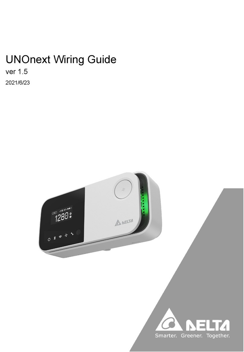
【UNOnext indoor air quality monitor】
Email: [email protected]
[email protected]
256 Yangguang Road, Neihu, Taipei 11491, Taiwan
TEL: +886-2-8797-2088
Delta Electronics, Inc.
Quick start guide ver 1.2
2020
【Overview】
【Display and button functions】
UNOnext is an all-in-one air quality monitor that can detect temperature, humidity, carbon dioxide, PM2.5,
PM10, total volatile organic compounds (VOCs), formaldehyde, carbon monoxide, and ozone, which can all
be monitored visually through sensors. It can be directly connected to a fresh air system to improve air
quality, which not only saves energy, but also lets users breathe fresh air with peace of mind. It is suitable for
many different types of environments, including residential buildings, commercial buildings, medical
institutions, and places sensitive to air quality, such as nursing homes and day care centers.
This product detects various types of air pollution that may have an adverse effect on the human body.
It provides NFC tags for easy opening of the APP and viewing real-time information on the site’s air quality.
Appearance Display layout
Function definition
The product has two functions which are “smart control” and “IAQ sensing", -- default is "IAQ sensing".
‧The power indicator lights up after power is connected. If the power indicator does not light up, please
make sure that the power cord is firmly installed.
‧The air quality indicator turns blue after the device is turned on, which means that it is booting up. After
booting is complete, it changes color according to the air quality status, in which green is good, yellow is
moderate, red is bad, and purple is polluted.
‧The product has built-in multiple sets of sensors, and the values are displayed in rotation. If the value of a
sensor exceeds the threshold, the warning icon is been displayed in the upper left of the screen.
‧In “smart control”. double-press the button (within 5 seconds) to change the fan speed and control mode.
The default is “smart control” and may be switched into the following modes. If the interval between key
presses is more than five seconds, the equipment is turned on and off. It will enter “smart control” when it
is turned on again. In "IAQ sensing", the button can turn on/off night mode (the screen and indicators
on/off).
【Detailed description】
Smart control layout IAQ sensing layout
‧Use the APP for Wi-Fi configuration. The APP provides instructions on operating procedures. Please verify
that the controller you purchased is the Wi-Fi version. The Wi-Fi connection indicator turns on after
connecting to Wi-Fi.
‧The product was calibrated in the factory, and no additional calibration is required. If a sensor value is
affected by the environment at your site, please contact the distributor for manual calibration.
‧This controller has built-in multiple sets of precision sensors. Collision and vibration during transportation
may affect its readings. It is recommended that you turn it on and install it, and then wait for about one hour
until the chamber reaches balance.
• After you turn on the device, the sensor needs to warm-up for 10 seconds or less for PM2.5, PM10, and
carbon dioxide, and 5 minutes for formaldehyde, carbon monoxide, ozone, and TVOC. Sensor data is
updated every 3 to 6 seconds (depending on the type of sensor).
•The CO2component is a precision instrument that provides automatic calibration. This product was
calibrated at the factory before shipping. After a week of continuous operation, it will automatically calibrate
every week. If the component encounters vibration when it is reinstalled in a different place, the data
values may drift.
【Note】Follow the instructions below to facilitate the automatic calibration of CO2components.
‧This product needs a continuous power supply, please install it in a fixed position
‧The indoor environment reaches the level of the outdoor environment for four consecutive hours each week
Appearance
Appearance
Multi-func. button
mode/fan speed/bind
IAQ indicator
Power
Bluetooth link
Wi-Fi link
Equipment status
Filter health
NFC tag
Sensor
values
By-pass
valve status
Fan speed
Filter health
Control
mode
Sensor category
Reminder of
exceeding
threshold
Turn off
ventilation
equipment
Smart
mode
Manual
control
low speed
Manual
control
medium
speed
Manual
control
high speed
‧“Smart mode” will turn ventilation equipment on and off depending on whether the air quality exceeds the
threshold or not. There are two control modes: Turbo and UNOECO. Users can set a threshold on the APP
to determine activation conditions.
Icon Smart mode plan Description
Turbo If it exceeds the threshold, the equipment will operate at full speed and
exchange air until the air quality improves.
UNOECO If it exceeds the threshold, the equipment will change fan speed relying on the
changing rate of the IAQ index to achieve low noise, power saving and health.
Indoor air quality indicator description
Indoor air quality indicator color (status) PM2.5 (ug/m3) PM10 (ug/m3) CO2 (ppm)
Green (Good) 0- 28 0- 60 400-800
Yellow (Moderate) 29- 35 61-75 801- 1000
Red (Bad) 36- 140 76- 3001001- 4000
Purple (Polluted) >140 >300 >4000
Function Screen layout Button function
Smart control Sensor values, control status
and mode, filter health
Switch control mode and fan speed
IAQ sensing Sensor values iteration Screen and indicator on/off switch
Pin Pin name Definition
1GNDGround
2AI1Analog input-1 External temperature sensor
3AI2 Analog input 2
4NO4 Digital output - HF
5NO3 Digital output - MF
6NO2 Digital output - LF
7NO1 Digital output – ON/OFF
8B2 Modbus slave B
9A2 Modbus slave A
10 B1 Modbus host B
11 A1 Modbus host A
12 GNDGround
13 Vin 9-24V DC input
14 Vout 9-24V DC output
Number Switch Definition ON OFF
1Modbus terminal resistor
2Modbus slave position [3]
3Modbus slave position [2]
4Modbus slave position [1]
5Modbus slave position [0]
6Maximum fan speed [1]
7Maximum fan speed [0]
8Control mode selection
* The above are the default states of the DIP switches
Table1. Terminal block pin function definition Table2. DIP switch function definition
【Note】The default activation standard for CO2is 1,000 ppm, PM2.5 is 28 ug/m3, PM10 is 60ug/m3,
which can be selected in the APP. The color of the indicator light is based on the default range.
Keep away from light
heat source
Keep away
from fire
Keep away from
cooking area
Do not use a
cleaning agent
Indoor use
only
Avoid
direct sunlight
Keep away from
air-conditioning outlet
【Installation precautions】
【Note】The temperature module built into this product has been calibrated in the factory, but the
accuracy may be impacted by the installation environment, such as nearness to a heat source or high
air flow. To get more accuracy, calibrate the product after installation. Wait for one hour after
installation for calibration. Please contact dealers and local sales for detailed information.
Adapter connector
Terminal block
DIP switchFilter reset
Wi-Fi power LED (red)
Wi-Fi connection LED (green)
【Wiring diagram – Connect the equipment via RS485.】
Power on verification
‧After the product has been installed, the power indicator lights up after the power is connected, and the air
quality indicator turns blue, which means the device is turning on at this time. If green or yellow appears, it
means that the device has completed booting and the current air quality status is displayed. If the power
indicator does not light up, please verify that the power cord is properly connected and that there is a
supply of power.
‧Wireless model has Bluetooth and Wi-Fi functionality. Users can go to the iPhone app store or Android play
store to download the APP.
【Installation guide】
Installation steps
‧The product is recommended to be installed at a height of 80-150 cm (31.5-59 inches).
‧Use the wall mount included in the box to install it on the wall, or install in a power box. The wall mount has
screw hole spacing (60mm and 84mm) suitable for power boxes in multiple countries, but the power box
must be installed horizontally as shown in Figure 1.
‧Verify that the power supply and data lines are laid out according to specifications before installation
‧As shown in Figure 2, install it on the wall mount and verify that all four buckles are installed and fixed.
‧As shown in Figure 3, use a hexagonal screwdriver to fasten the M4 hex socket screws to complete the installation
【Note】Power source notice
This product uses a 9-24V DC power supply. AC power must be converted to the required power source or
use the power adapter in the box. The output voltage Vout is the same with input voltage Vin. Output
voltage should be 12V when using a 12V power adapter.
Fig1. Fig 2. Fig3.
【Note】
The product supports control of energy recovery ventilation and inline fan. Regarding the compatibility
of equipment brands and models, please contact your dealer and local sales for technical evaluation
before purchasing.
Wiring diagram Fan speed levels Control interface
【Care and maintenance】
Place in an appropriate environment
‧This product is not waterproof. The installation location should be away from water sources, such as
beverages, basins, bathtubs, bathrooms and so on. Protect it from moisture in wet weather such as rain,
snow or fog.
‧To ensure the accuracy of the detector, the installation position should not be in the vicinity of sunlight or
other heat sources.
‧The interior has a variety of precision detectors. Avoid violent vibrations, which may cause the detector
reading values to shift, and a stable balance may take a longer time.
‧Operate at temperatures between 0oC and 50oC (32oF to 122oF). Do not expose the product to extreme
heat sources, such as radiators or fireplaces, that exceed 100oC (212oF).
‧Covering the device, or placing it in an enclosed space may cause it to inaccurately detect the air quality of
the room.
Using connectors and ports
Do not force the connector into the port. Check the port for foreign objects. If the connectors and ports do not
fit easily, it may be because they do not match each other. Make sure that the connector matches the port and
that the connector is aligned to the correct location corresponding to the port.
【Note】Not following instructions may result in damage to the product or other items.
12V GND B A
Connect A1 and B1 with the equipment’s A and B, the recommended wire to use is 22AWG Shielded Foil
Twisted-Pair (SFTP)
【Place of origin】
This product is made in Taiwan. The place of origin is No. 256, Yangguang St., Neihu Dist., Taipei City,
Taiwan (R.O.C.).
Any Changes or modifications not expressly approved by the party responsible for compliance could void
the user’s authority to operate the equipment.
This device complies with part 15 of the FCC Rules. Operation is subject to the following two conditions:
‧This device may not cause harmful interference, and
‧This device must accept any interference received, including interference that may cause undesired operation.
Note: This equipment has been tested and found to comply with the limits for a Class B digital device, pursuant
to part 15 of the FCC Rules. These limits are designed to provide reasonable protection against harmful
interference in a residential installation.
This equipment generates, uses and can radiate radio frequency energy and, if not installed and used in
accordance with the instructions, may cause harmful interference to radio communications. However,
there is no guarantee that interference will not occur in a particular installation. If this equipment does cause
harmful interference to radio or television reception, which can be determined by turning the equipment
off and on, the user is encouraged to try to correct the interference by one or more of the following measures:
‧Reorient or relocate the receiving antenna.
‧Increase the separation between the equipment and receiver.
‧Connect the equipment into an outlet on a circuit different from that to which the receiver is connected.
‧Consult the dealer or an experienced radio/TV technician for help.
【Note】
To connect multiple devices you must set different Modbus slave address. Please reference the user
manual of the device to config slave address.
【Connect multiple devices】
The product can connect up to 4 of the same devices via RS485 in series through linear topology. At this time,
each device will follow the same control mode and fan speed level.
IC ID: 26414-UNOC07X011
Warning:
This device complies with Industry Canada licence-exempt RSS standard(s).
Operation is subject to the following two conditions:
‧this device may not cause interference, and
‧this device must accept any interference, including interference that may cause undesired operation of
the device.
Le présent appareil est conforme aux CNR d’Industrie Canada applicables aux appareils
radio exempts de licence. L’exploitation est autorisée aux deux conditions suivantes :
‧l’appareil nedoit pas produire de brouillage, et
‧l’utilisateur de l’appareil doit accepter tout brouillage radioélectrique subi, même si le brouillage est
susceptible d’en compromettre le fonctionnement.
【Caution】
【Canada: Industry Canada (IC) Statement】
FCC ID: H79-UNOC07X011
Contains FCC ID: SH6MDBT50Q
Federal Communication Commission Interference Statement
【NCC statement 】
「取得審驗證明之低功率射頻器材,非經核准,公司、商號或使用者均不得擅自變更頻率、加
大功率或變更原設計之特性及功能。低功率射頻器材之使用不得影響飛航安全及干擾合法通
信;經發現干擾現象時,應立即停用,並改善至無干擾時方得繼續使用。前述合法通信,指
依電信管理法規定作業之無線電通信。低功率射頻器材須忍受合法通信或工業、科學及醫療
用電波輻射性電機設備之干擾。」
【APP and website links】
The product is equipped with wireless technology and can use an APP and website to monitor the air
quality status, which can be obtained using the following QR codes. (For the wireless model only). Please
go to the official website to learn about how to use UNOnext.
https://isdweb.deltaww.com/resources
iOS APP Android APP UNOweb Doc. & Resources
【Order listings】
Model
number
Product
number
BLE
Wi-Fi
temp./
humid. CO2LuxPM TVOC CO
UNO -6SW ● ● ● ● ●
UNO -9SW ● ● ● ● ● ● ● ●
UNO -7HW ● ● ● ● ● ●
● ● ● ● ●UNO-7TR
● ● ● ●
UNO-6SR
* Not available currently
Ozone*
UNO-C01X001
UNO-C01X001
UNO-C07X011
UNO-C07X011
UNO-C07X011
Do not inject contaminants
Do not directly inject contaminants containing gases or particulate matter. Exposure to excessive contami-
nants can permanently damage the sensor.
Do not repair this product yourself
The product does not have components that users can repair themselves. Do not attempt to open it. Once the
warranty sticker breaks, the warranty is void.
【Note】Do not insert objects through the vents, which may be dangerous and damaging.
Cleaning the exterior of UNOnext
To clean the product, unplug the power cord and all wiring.
Wipe with a soft, cotton-free cloth. Avoid moisture at any openings on the device body. Please do not spray
liquids directly onto it.
Trial run with the equipment
‧Switch function to smart control, turn all the DIP switches up, press the multi-func. button to power on,
release the button after the filter health LED blinks, and confirm that the screen has changed successfully
after restarting, and then restore the DIP switches as previously stated.
•In RS485 control mode, if the equipment is successfully connected, the equipment status indicator is
static on or off when the equipment is on or off. If it is not correctly connected, the equipment status
indicator will keep blinking.
•The installer can verify ventilation volume by switching to manual mode and corresponding fan speed.
•After a period of time, the health of the filter will return to zero. At this time, it is recommended to replace the
filter. After the replacement, you can press and hold the filter reset button on the back of the product to reset.
1 2 3 4 5 6 7 8
DIP switches
Prohibit live line operation
When the installer configures DIP switches and terminal connector, be sure to power off before execution
and then power on after.
Dip switches
Dip switches
Dip switches
Dip switches
ID: 0x67ID: 0x66ID: 0x65ID: 0x64
Use Delta ERV “VEB250AT3” as an example
MODBUS(RTU)
A B
ID: 0x66
ID: 0x65
ID: 0x67
ID: 0x64
6 7
Unlimited 1 level
6 7
3 levels
6 7
2 levels
6 7 8
RS485
Delta ERV “VEB250AT3”
Other manuals for UNO-C07X011

1

This manual suits for next models

6

Other Delta Measuring Instrument manuals

Delta DVP04TC-H2 User manual

Delta

Delta DVP04TC-H2 User manual

Delta R4E User manual

Delta

Delta R4E User manual

Delta LTL2000S User manual

Delta

Delta LTL2000S User manual

Delta DPM-D520I User manual

Delta

Delta DPM-D520I User manual

Delta WS-6975 User manual

Delta

Delta WS-6975 User manual

Delta DPM-C320 User manual

Delta

Delta DPM-C320 User manual

Delta RetroSign GRX User manual

Delta

Delta RetroSign GRX User manual

Delta UT-191T User manual

Delta

Delta UT-191T User manual

Delta PPM P1_120 User manual

Delta

Delta PPM P1_120 User manual

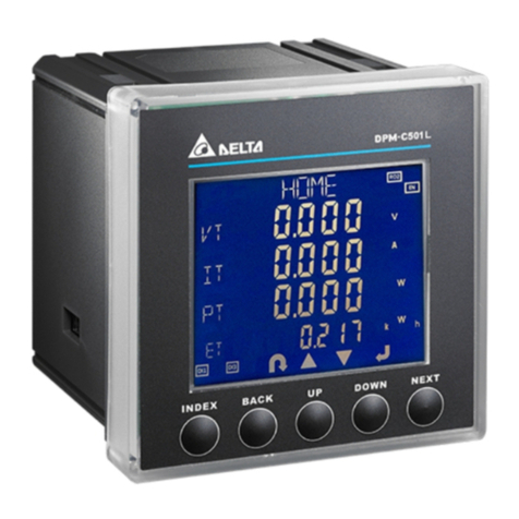
Delta DPM-C501L User manual

Delta

Delta DPM-C501L User manual

Delta DPM-C510 User manual

Delta

Delta DPM-C510 User manual

Delta DVP-ES2 User manual

Delta

Delta DVP-ES2 User manual

Delta OR-AE-1306 User manual

Delta

Delta OR-AE-1306 User manual

Delta LTL-XL User manual

Delta

Delta LTL-XL User manual

Delta dvp04pt-s User manual

Delta

Delta dvp04pt-s User manual

Delta RetroSign GR1 User manual

Delta

Delta RetroSign GR1 User manual

Delta DVP08NTC-S User manual

Delta

Delta DVP08NTC-S User manual

Delta MessageMaxx DMS-279 Manual

Delta

Delta MessageMaxx DMS-279 Manual

Delta DPM-C501L User manual

Delta

Delta DPM-C501L User manual

Delta REVEZ-HD-TRIO DVB-T/T2 User manual

Delta

Delta REVEZ-HD-TRIO DVB-T/T2 User manual

Delta LTL-XL User manual

Delta

Delta LTL-XL User manual

Delta EMS 32-011 User manual

Delta

Delta EMS 32-011 User manual

Delta TECK II User manual

Delta

Delta TECK II User manual

Delta DPM-C530A User manual

Delta

Delta DPM-C530A User manual

Popular Measuring Instrument manuals by other brands

Klein Tools RT390 instruction manual

Klein Tools

Klein Tools RT390 instruction manual

Solinst 101 Replacement guide

Solinst

Solinst 101 Replacement guide

Exotek MC-400 user manual

Exotek

Exotek MC-400 user manual

SciGene Professional Gen 2 G-Force Snapshot user guide

SciGene

SciGene Professional Gen 2 G-Force Snapshot user guide

SPECTRO SPECTRO xSORT Original operating instructions

SPECTRO

SPECTRO SPECTRO xSORT Original operating instructions

Laurus Rad-id user manual

Laurus

Laurus Rad-id user manual

Edwards FSRZI-A Installation sheet

Edwards

Edwards FSRZI-A Installation sheet

Honeywell COCON 26 DRA-LP/MP MAINTENANCE AND ASSEMBLY MANUAL

Honeywell

Honeywell COCON 26 DRA-LP/MP MAINTENANCE AND ASSEMBLY MANUAL

TRAMEX Skipper Plus user guide

TRAMEX

TRAMEX Skipper Plus user guide

YOKOGAWA MT210 user manual

YOKOGAWA

YOKOGAWA MT210 user manual

PCE Instruments PCE-320 manual

PCE Instruments

PCE Instruments PCE-320 manual

Vetek EBW-2D user manual

Vetek

Vetek EBW-2D user manual

Maico HY 5 Mounting Instructions and Directions for Use

Maico

Maico HY 5 Mounting Instructions and Directions for Use

Konica Minolta VI-9I brochure

Konica Minolta

Konica Minolta VI-9I brochure

Hanna Instruments HI97105 instruction manual

Hanna Instruments

Hanna Instruments HI97105 instruction manual

Schaller Humimeter BLW operating manual

Schaller

Schaller Humimeter BLW operating manual

Drawell TrueX XRF user manual

Drawell

Drawell TrueX XRF user manual

CONDTROL Qb user manual

CONDTROL

CONDTROL Qb user manual

manuals.online logo
manuals.online logoBrands
  • About & Mission
  • Contact us
  • Privacy Policy
  • Terms and Conditions

Copyright 2025 Manuals.Online. All Rights Reserved.