DeltaTRAK FlashLink 40528 User manual

Quick Start Guide
Models 40528, 40528-0X
Certied Vaccine PDF Data Logger

2www.deltatrak.com
Getting Started with the FlashLink Certified Vaccine PDF
Data Logger
Installing the Software
Insert the FlashLink Program Manager ash drive into a USB port of a PC.
There are two les, a license and FlashLink.exe software installation le. Save
these to the PC hard drive. If you do not have a ash drive and only have the
license, download the software from the DeltaTrak web site
http://www.deltatrak.com/support/software-drivers
Note: The license key can be used on two computers.
Navigate to the les on the hard drive. Open the license document and note the
license key number. Double click on FlashLink.exe and follow instructions in the
dialog boxes that appear on the screen. When you get to the Enter License
dialog box, key in the number provided in the license and select Activate.
The FlashLink shortcut icon will appear on the desktop and system tray. Double
click the icon to
open the program.
FlashLink Program
Manager runs
automatically and
detects when a
data logger is
connected to
the USB port for
programming and
downloading.
During software
installation,
subfolders for
PDF and CSV
le storage are
created in the main FlashLink folder. When a data logger is downloaded, PDF
and CSV reports are automatically generated and saved in these folders for
record keeping.
Programming the Logger
Right click on the FlashLink icon to open the main menu.
• Options - Customize FlashLink software display, le storage
location, report appearance, enable 21 CFR administration
• Setup - Create/save logger conguration les, including logging
periods, intervals, alarm thresholds
• Import - Import and reuse saved Setup conguration les
• ColdTrak File Processing - Send data les to ColdTrak Server Database
FlashLink Icon

3www.deltatrak.com
(optional cloud service)
• Data Analysis - View trends and details,
compare multiple charts from a single data
logger or several loggers
• About - Displays FlashLink software
version, provides a link to Help les
• Update - Checks DeltaTrak server for
available FlashLink software updates
• Exit - Closes FlashLink application
FlashLink Help is a complete user guide
that is accessible from any screen by
clicking on the [ ? ] symbol in the top, right
corner. Specic topics can easily be found in
the table of contents or by using the keyword search bar.
Plug the FlashLink Data Logger into the USB port of the computer, select
Setup to open the Logger Configuration Wizard. The current conguration
is displayed. Click on Next to access Logging Options and select desired
conguration parameters. New Configuration window will conrm settings,
select Next and OK to upload the conguration to the data logger. The
Reactivate option will keep the settings currently programmed in the unit.
Once congured, the logger can now be activated, downloaded and reset
without having to use FlashLink Program Manager. The software will be needed
when conguration changes are required.
Alarm Notifications
The alarm and audible buzzer must be enabled during logger conguration,
including buzzer interval and alarm set points.Thebell icon,ashing LEDand
buzzerwill activate with the rst alarm event. Pressing either the START or STOP
button will silence the buzzer and stop the red LED from ashing, LEDs and
iconsremain on the LCDuntil the logger is reset orrecongured.
Alarm delay can be programmedto triggeronly when temperature
excursionscontinue beyond theset delayperiodthat starts with
therstalarmevent. The buzzer can be temporarily silenced by pressing the STOP
or START button and will restart when the next temperature readingisrecorded.
Level 1 High/Low Alarm
Numeral 1 icon High or Low
Buzzer sound 3 beeps at set interval
Options
Setup
Import
ColdTrak File Processing
Data Analysis
About
Update
Exit
FlashLink Icon

4www.deltatrak.com
Level 2 x-High/x-Low Alarm
Numeral 2 icon Red LED ashes once High
or Low Buzzer sound 3 beeps at set
interval with third beep durration longer and
double Flash of Red LED
The LCD Screen
The Glycol Bottle
This digital data logger (DDL) features a stainless steel sensor enclosed in a
bottle of propylene glycol. The cable has a stereo jack for quick disconnect
to easily detach the logger and download data. The glycol buffered sensor
emulates products in the storage unit and keeps the sensor from setting off
false alarms due to rapid temperature uctuations caused by frequent door
opening during normal daily use.
Place the glycol bottle sensor in the center of the refrigerator or freezer, attach
the logger to the outside of the unit. Allow at least 1 hour for the sensor to reach
equilibrium before activating the logger. When the sensor doesn’t have enough
time to equilibrate to the internal temperature, it will trigger a false alarm if it is
still above the high alarm set point.
Starting the Logger No Delay
Press and hold the START button, The Logger ashes the word “Strt” while
you are holding the button. When the device starts logging the green LED
ashes 3 times and the buzzer beeps three times.The LCD displays the current
temperature. The rst data point from the data record (log) is recoded at the end
of the rst Logging Period.
Starting the Logger With Delay
Start delay may be programmed in the Logger to allow it to acclimate to the
environment before logging. The LCD displays the delay countdown timer,
which refreshes every minute. The start delay can be bypassed when such
action is required, so the device can start logging immediately. To bypass
the delay press and hold the START button. The LCD ashes while the
button is down. When the Logger starts logging the LCD displays the current
1
11
5 6
43
10
2 12
8
9
S
MAX
MIN
AVG
HI
LO
day
hrs
min
7
°C
°F
1. Sensor/alarm channel enumerator
2. Shadow logging icon
3. Active mode icon
4. Stop mode icon
5. High and low alarm arrows
6. Alarm icon
7. °C, °F scale icons
8. Day, Hours and Minutes icons
9. High and Low Alarm set point icons
10. Statistical icons
11. 4 digit numerical display
12. Battery Capacity Gauge

5www.deltatrak.com
temperature reading.The start delay can also be canceled by pressing and
holding down the STOP button.
Daily Statistics on LCD
The Logger maintains a record of Min, Max, Average values and time in alarm.
The Stats are available for viewing after the rst data point is recorded. Enter
Stats View mode by clicking the START Button.
The Stats will be displayed in sequence after each subsequent click of the
START button following this order:
• Average [AVG]
• Min
• Max
• High
• Time above High
• Low
• Time below Low
• x-High
• Time above x-High
• x-Low
• Time below x-Low
Click the STOP button to exit this mode or do not click any button for 30 sec to
have it timeout.
W.H.O. Activated Mode
The Logger can store statistical data for a number of days and the record can be
viewed on the LCD one day at time.This mode complies with the specication
by the World Health Organization (WHO) for vaccine Data Loggers which
requires the Logger to store daily statistics for 30 days and to view these on the
device itself. This mode is a conguration option and disabled by default. When
enabled the Stats Review mode is extended to viewing all recorded data up to
30 days back. Press and hold the START button during Stats Review mode. The
LCD displays a number from 1 to 30 for the days. The Bell icon is displayed if
the day has alarm. Release the button on the day of interest and click through its
statistical data. The example shows the selection of day 10 and it has alarm
Inserting Waypoints
If a temperature reading needs to be conrmed at a check point during
transportation or storage, a waypoint can be inserted as a marker to ag date/
time of this event. The waypoint option must rst be enabled during logger
conguration.
Press and hold the START button until FLAg appears on the
LCD and release when it stops ashing. The waypoint has
been inserted and the LCD will revert to current temperature
reading. When reports are created at the end of the logging
period, waypoints appear as a vertical line on the graph and
have an asterisk in the data table.

6www.deltatrak.com
Resetting After Download
Resetting the logger will clear recorded data from
its memory. After saving the PDF and CSV les,
remove the logger from the USB port, the LCD
should still display StoP. To restart the unit without
changing settings, Press and hold the STOP button.
The Logger displays ashing “rSt” while the button is
down. The logger will then revert back to displaying the
battery icon on the LCD. This indicated the logger was
successfully restarted back to the original conguration.
The Logger can be re-congured in this way a limited number of times.
Stopping the Logger
If monitoring needs to continue after the logger is
downloaded, do not remove the sensor from the
storage unit. Press and hold the red STOP button
until StoP appears on the LCD without ashing.
Detach the logger from the sensor cable, making
sure the glycol bottle remains inside with the
vaccines.
Downloading Reports
Option 1 - When the STOP button is pressed,
FlashLink PDF Data Logger automatically generates
PDF and CSV reports using its onboard software
and saves these les to an internal memory. This
allows personnel to download and save reports on
any PC and does not require FlashLink Program
Manager software.
Option 2 - Download data to a PC which is running
FlashLink Program Manager software. When a data
logger is plugged into the USB port, the software
automatically detects the logger, generates
and saves Adobe®PDF and CSV reports to the
subfolders in the FlashLink main folder.
Configuration by .TXT File
This device allows for the user to congure their own settings by a text le,
read with the Notepad application or other text editing software. The le called
CONFIG.TXT can be edited and saved directly when it is in the folder of the
Logger, copy and paste it into the folder or drag and drop from another folder.
This .TXT le contains conguration data in the form of Keyword and Value
pairs, separated by equal sign. Some keywords will be easy to understand,
below is a table with each keyword and description. If all keywords are correct
and the corresponding values are acceptable the Logger will respond with three
Succeeding PDF Report pages list
all data points in table format

7www.deltatrak.com
Keyword Description
SCALE Set to make Fahrenheit the primary scale
LEDS Set to enable Green and Red LEDs indication
BUZZER Set to enable Buzzer for alarm indication
ALARM Set to enable all alarm functions
HIDE_ALARM_BARS Set to hide horizontal alarm bars in the PDF chart report
SB Set to enable stopping by the STOP button
CF_BUTTON Set to enable C/F scale toggle with the STOP button
OUT_OF_RANGE_GAP Set to hide over/under range points on the PDF chart
DS Set to enable daily stat
LPST Set to show stop time as the time of the last data point
WSet to enables way-point insertion feature
LP Set to enable Loop Mode
TD Set to allow test download without stopping logger
BG Set to display battery gauge
ST Set to enable self-tests visualization after reset
SR Set to enable reset of stats by holding Stop during Stats preview
BEEP_ON_CLICK Set to enable beep on click
RTO Set to enable relative time logging when RTC is not set
STF Set to stretch data on the chart to fit the plot area
DF Set to enable very low power in deep freeze
WCA Set to enable Alarm state clearing by insertion of a way-point
PS Set to keep the alarm summary data unaffected by data loop condition
SDB Set to enable bypassing of Startup Delay By pressing the Start button
HC Set to prevent CONFIG.TXT from automatically showing in Logger’s folder
AS Operating state : Waiting=0,Stopped=3
DATE_FORMAT Set date format DATE_FORMAT=0 for (mm/dd/yyyy) (default), DATE_FORMAT=1 for (dd/
mm/yyyy), DATE_FORMAT=2 for (yyyy/mm/dd)
TIME_ZONE Time zone applied to all absolute dates
LOGGING_INTERVAL Logging interval expressed in seconds
START_DELAY Start up delay in minutes
• You can reconfigure the Logger only before it has been started
• The name of the file must be “CONFIG.TXT” or the Logger will reject it
• The content of the file must include only supported configuration keywords
• Only one keyword can be written on a single line
• Comments, inserted in the file will be ignored and will not be saved into the Logger
positive beeps and green LED ashes. If there are any errors during the process
a le will be created called “ERROR.TXT” with a message explaining the reason
for the rejection of the le

6121 23C2
P.O. Box 398 Pleasanton CA 94566
(925) 249-2250 (800) 962-6776
www.deltatrak.com
DeltaTrak Corporate
Guadalajara, Mexico
+52-33-3188-3161 / 36712190
www.deltatrakmexico.com
DTI Mexico International
Shenzhen China
+86-755-8442-9388/2837-2741
2837-2664 | 8923-2778
www.deltatrakchina.com.cn
DTI China Limited
NT, Hong Kong
+852-3568-5538
www.dtiap.com
DTI Asia Pacific
Auckland, New Zealand
+64 9 5757 886
www.deltatraksouthpacific.com
DTI South Pacific
Osaka, Japan
+81-6-6616-5900
www.dtijapan.co.jp
DTI Japan Limited
Antwerp Belgium
+32 (0) 3-455-61-25
www.deltatrakeurope.be
DTI Europe bvbaDTI South America SA
Santiago, Chile
+562 2758 2866
+569 7477 1061
www.deltatraksouthamerica.com
Western Cape, South Africa
+27 79 519 5047
www.deltatrak.co.za
DTI South Africa Limited
Troubleshooting
Contact Tech Support:
Phone: 925-249-2250 Ext 5120 Toll Free 800-962-6776 US & Canada
Email: [email protected]
Keyword Description
EXT_HI_ALARM Extreme high alarm temperature
HI_ALARM High alarm temperature
LO_ALARM Low alarm temperature
EXT_LO_ALARM Extreme low alarm temperature
EXT_HI_ALARM_CTR Max count of Extreme high alarm cumulative time points
HI_ALARM_CTR Max count of High alarm cumulative time points
LO_ALARM_CTR Max count of Low alarm cumulative time points
EXT_LO_ALARM_CTR Max count of Extreme low cumulative time points
ALARM_DELAY Delay alarm indication in minutes
SKIP_ALARM Skip alarm in data points from start of logging
AI Sets alarm interval in sec, Default is 5 sec
BHT Button holding timeout for start
DFT Threshold of Deep freeze state when the LCD is turned off for super low power
BV Stores the last reading of the battery voltage
PMT Timeout of paused mode, specified in minutes (255 min max)
NOTE Custom note for customer
This manual suits for next models
1
Table of contents
Other DeltaTRAK Data Logger manuals
DeltaTRAK
DeltaTRAK FlashLink 22367 User manual
DeltaTRAK
DeltaTRAK FLASHLINK RTL User manual
DeltaTRAK
DeltaTRAK FlashLink 40909 User manual

DeltaTRAK
DeltaTRAK FlashLink 40909 User manual
DeltaTRAK
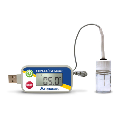
DeltaTRAK FlashLink 40527 User manual
DeltaTRAK
DeltaTRAK FlashLink User manual
DeltaTRAK
DeltaTRAK FlashLink 40516 User manual

DeltaTRAK
DeltaTRAK FlashLink 40527 User manual
DeltaTRAK
DeltaTRAK FlashLink 20932 User manual
