DeltaTRAK ThermoTrace 15050 User manual
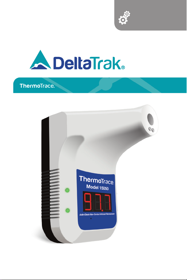
Auto-Check Non-Contact Infrared Forehead Thermometer K3
Please read this manual before operating unit.
Important safety information inside.
User Guide
Model 15050

Please read the following info first:
Before using the device, SCAN the QR Codes
below to access the following:
1. DeltaTrak User Manual:
https://www.deltatrak.com/15050
2. Support and Technical Services:
https://www.deltatrak.com/support/tech-support
3. Warranty:
https://www.deltatrak.com/support/warranty
5. Introduction Video:
https://www.deltatrak.com/15050-v1
6. Example of Use Video:
https://www.deltatrak.com/15050-v2
4. How Did We Do? (Customer Satisfaction Survey):
https://www.deltatrak.com/survey
1
21
3
Table of Contents
Configuration
Specifications
Configuration ........................................................................................................ 1
Specifications ....................................................................................................... 1
Status Descriptions ............................................................................................... 2
Operating Instructions ........................................................................................... 2
Installing/Replacing Battery .................................................................................... 3
Mounting Instructions ............................................................................................ 4
Helpful Tips for Reliable Results.............................................................................. 4
Software User Guide ............................................................................................. 5
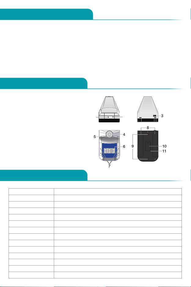
1. Tripod Mounting Hole
2. USB Interface
3. On/Off Switch
4. Infrared Probe
5. Infrared Distance Sensor
6. Temperature Display
7. Alarm Light
8. Double-Sided Tape Area
9. Wall Mount Connectors
10. Nameplate
11. Mode Switch Button Hole
8
910
11
4
7
5
6
Accuracy ±0.2 degrees (93°F – 113°F/34-45°C)
Alarm Flashing and Audible Alert
Measuring Distance 2in – 4in (5cm – 10cm)
LCD Screen Digital Display
Power USB Charging Cable/1x Battery (18650 Lithium-Ion)
Wall Mount Nail/Hook; Adhesive Backing
Operating Environment 50°F – 104°F (10°C – 40°C)
Measuring Range 32°F – 122°F (0°C – 50°C)
Response Time 0.5 Second
Input DC 5V
Weight 12oz (350g)
Dimensions 7in X 4.5in X 5.5in (170mm X 115mm X 140mm)
Standby Mode Approximately 1 week
Memory 999 Measurements
2
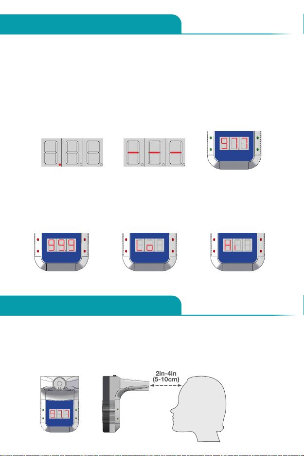
Status Descriptions
Operating Instructions
• Standby Mode: When the device is in standby mode the red light beneath the
temperature display will appear. (Figure 1)
• Low Power: When power is low, three dashes will appear across the
temperature display. (Figure 2)
• Normal Temperature: When the temperature reading is within the normal range,
green lights will flash and the device will beep one time. (Figure 3)
• Abnormal Temperature: When the temperature reading is outside of the normal
range, red lights will flash and the device will beep twice. (Figure 4)
1. Allow device to acclimate to room temperature for 30 minutes before using.
2. Stand directly in front of thermometer - no more than 2in to 4in (5cm to
10cm) away. The middle of the forehead should be level with the probe. The
device will beep and display the temperature reading on the LCD. (Figure 7)
Fig. 1 Fig. 2 Fig. 3
Fig. 6Fig. 5Fig. 4
Fig. 7
• Lo: “Lo” will appear on display when temperature reading is lower than normal
range. (Figure 5)
• Hi: “Hi” will appear on display when temperature reading is higher than normal
range. (Figure 6)
2in-4in
(5-10cm)
3
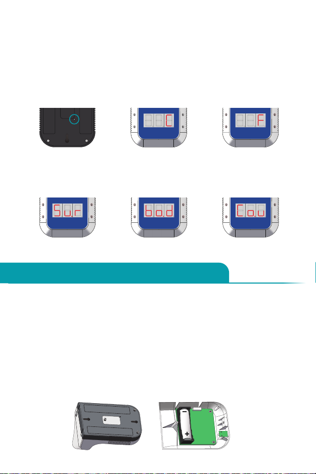
3. To select the Temperature Scale (Celsius or Fahrenheit), insert a 3mm
screwdriver (or other tool) into the Mode Switch Button Hole on the
back of the device. (Figure 8)
4. Press the screwdriver (tool) into the hole to select the desired
Temperature Scale. (Figures 9 & 10)
5. To select the Measurement Mode (Surface or Body) or Memory, insert
0.1in (3mm) screwdriver (or other tool) into Mode Switch Button Hole,
press and hold for 3 seconds.
6. Continue pressing the screwdriver (tool) into the hole to select the desired
Measurement Mode (Sur for Surface; bod for Body) or Memory (Cou).
(Figures 11, 12 & 13)
Installing/Replacing Battery
1. Remove the screws holding the battery compartment cover in place.
2. Remove the battery compartment cover. (Figure 14)
3. Insert one 18650 Lithium-Ion battery, observing correct polarity. (Figure 15)
4. Place cover over battery compartment and re-insert screws.
The device includes a 18650 rechargeable Lithium-ion battery with overcharge
protection. Before installing, please charge the battery for 4 hours to ensure
full power. Due to freight regulations, Lithium-ion rechargeable batteries may
not be fully charged prior to shipping. When the original battery is depleted,
please ensure the replacement also includes overcharge protection.
Fig. 9 Fig. 10Fig. 8
Fig. 13Fig. 12Fig. 11
Fig. 14 Fig. 15

4
Mounting Instructions
Helpful Tips for Reliable Results
1. Ensure the electromagnetic environment is compatible for device operation.
2. When changing operating environment, allow the device to acclimate to
room temperature for 30 minutes.
3. Not recommended for use outdoors or under bright light.
4. Keep the device away from air conditioning units and fans.
5. Use only qualified, safety-certified batteries. Using unqualified or non-
rechargeable batteries may cause fire or explosion.
6. If the device does not operate after installing batteries, connect to USB
cable to charge battery.
Methods for mounting the device:
• Nail/Hook: Place nail hook(s) (located on back of device) onto nailed wall.
(Figure 16)
• Tripod: Screw the mounting hole (located on bottom of device) onto the
tripod until secure. (Figure 17)
• Adhesive Backing: Remove the paper covering the double-sided tape
strips and adhere to the backside of device. Remove paper on other side
of tape and adhere device to wall or other surface. (Figure 18)
Fig. 16 Fig. 18Fig. 17
Non-ContactInfrared
ForeheadThermometer
Model 15050

5
15050 Software User Guide
1. Download/Installation Process
• Copy and paste the link below into your browser.
https://www.deltatrak.com/software/ThermoTrace/ThermoTrace-Auto-Check-
IR-Thermometer-Software.zip
• Open zip file.
• Double click “ThermoTrace-Auto-Check-IR-Thermometer-Software”.
• Double click “TestACY.msi”.
• Click “More info”.
The software can only be used with the
Windows operating system.
• Click “Run anyway”.
• Screen will display: “Do you want to allow this app to make changes to
your device?” Enter Administrator Username and Password.
• Once download is complete, locate software in designated folder and
double click to open.
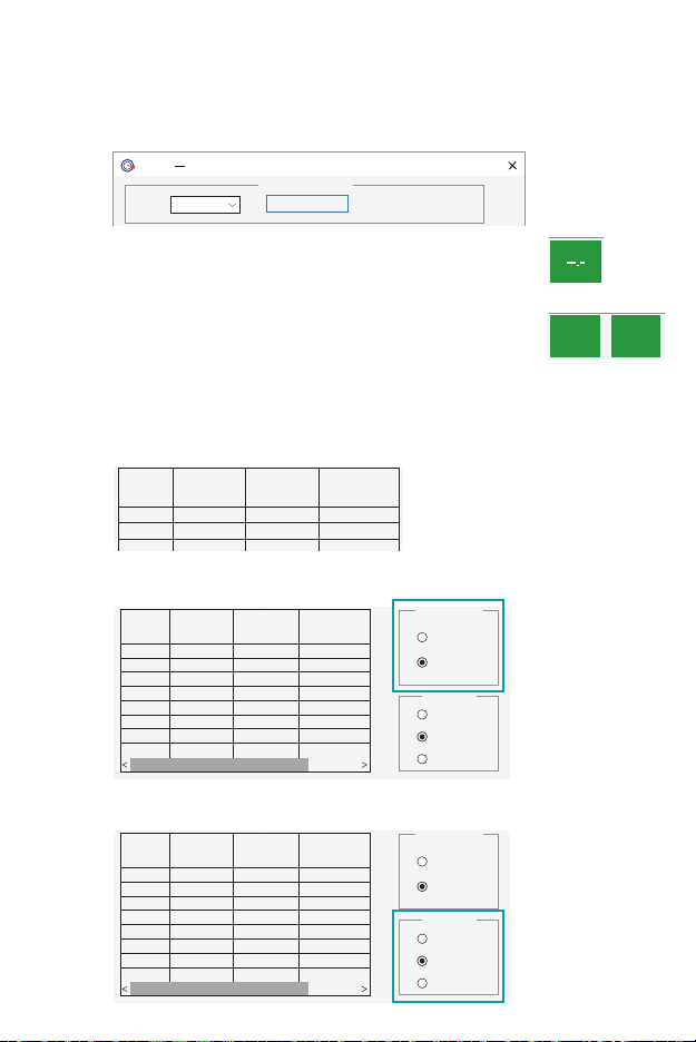
• The main page of the software automatically opens. There are no
measurements so the display shows “--.-”.
COM:
V1.03
Serial Port Operation
Disconnect
COM1
Quantity Test Time Test Value Environment
TESTACY E
success
Jul 6, 2020 Temp Statistics
Temp. Format
Work Mode
CelsiusC
FahrenheitF
Surface Mode
Count Mode
Current Date: 2020-07-02 Current Time: 15:08:52
Alarm Upper Limit:
Environment Temp.: 74.1F
F
99.5
Body Mode
Save As
6
• Connect thermometer to computer using USB cable and turn on. Click
“Connect”.
• If the connection is successful, “Success” will appear in green. (“Fail” will
change to “Success”)
• When this step is completed the connection is active and the temperature
data can be captured in real time.
Note:
1) Once the software is opened it will automatically find the appropriate COM
port. If the COM port displayed by the software is different from the computer
resource manager, it will not work properly. Manually set the serial port to the
corresponding serial port of the resource manager.
2) After the thermometer is turned off and then on again, click “Disconnect”
and “Connect”, or close software and open again. This step is necessary to
refresh the connected serial port so the data will display properly.
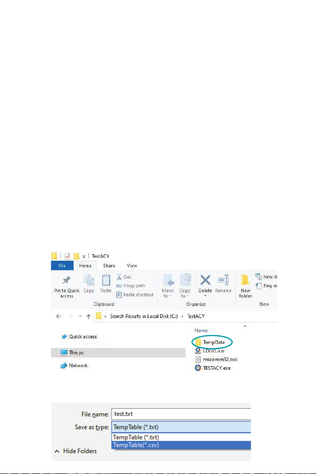
2. Data Viewing and Export
• TXT Data View: The subfolder, “TempData\\year\\month\\”, is
automatically generated within the TestACY folder. The format is Year/
Month/Day. The file type is TXT. If you cannot find the folder, use your
computer’s search function to locate it. The following data will be saved
for each measurement: Quantity (measurement number); Test Time;
Test Value (Temperature Reading); Environmental Temperature (Ambient
temperature at time of measurement).
• Excel Data View: Click “Save As” and select “CSV” format to export file
to Excel.
7
3. Software Introduction
• The software name is TESTACY. This image shows a successful
connection between the software and thermometer to capture the
measurement data. If the connection is good the screen will show
“Success”, otherwise it will show “Fail”.
COM:
V1.03
Serial Port Operation
Disconnect
COM1
Quantity Test Time Test Value Environment
TESTACY E
success
Jul 6, 2020 Temp Statistics
Temp. Format
Work Mode
CelsiusC
FahrenheitF
Surface Mode
Count Mode
Current Date: 2020-07-02 Current Time: 15:08:52
Alarm Upper Limit:
Environment Temp.: 74.1F
F
99.5
Body Mode
Save As
• When no data has been transmitted, such as when the
software is first opened, the display will show “--.-“.
COM:
V1.03
Serial Port Operation
Disconnect
COM1
Quantity Test Time Test Value Environment
TESTACY E
success
Jul 6, 2020 Temp Statistics
Temp.Format
Work Mode
CelsiusC
FahrenheitF
Surface Mode
Count Mode
Current Date: 2020-07-02 Current Time: 15:08:52
Alarm Upper Limit:
Environment Temp.: 74.1F
F
99.5
Body Mode
Save As
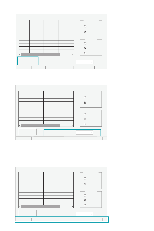
• In Body Mode when the captured temperature is within
the normal range the screen will display the reading and
“Normal”. When the temperature is outside the normal
range, the display will show the reading and “Abnormal”.
COM:
V1.03
Serial Port Operation
Disconnect
COM1
Quantity
1 15:12:30 97.5F 74.3F
1 15:12:32 97.7F 74.3F
Test Time Test Value Environment
TESTACY E
success
Jul 6, 2020 Temp Statistics
Temp.Format
Work Mode
CelsiusC
FahrenheitF
Surface Mode
Count Mode
Current Date: 2020-07-02 Current Time: 15:08:52
Alarm Upper Limit:
Environment Temp.: 74.1F
F
99.5
Body Mode
Save As
97.5F
Normal
• Example of data captured: 1) Quantity (measurement number); 2) Test
Time; 3) Test Value (Temperature Reading); 4) Environmental Temperature
(Ambient Temp)
COM:
V1.03
Serial Port Operation
Disconnect
COM1
Quantity
1 15:12:30 97.5F 74.3F
1 15:12:32 97.7F 74.3F
Test Time Test Value Environment
TESTACY E
success
Jul 6, 2020 Temp Statistics
Temp. Format
Work Mode
CelsiusC
FahrenheitF
Surface Mode
Count Mode
Current Date: 2020-07-02 Current Time: 15:08:52
Alarm Upper Limit:
Environment Temp.: 74.1F
F
99.5
Body Mode
Save As
97.5F Normal
• Either Celsius or Fahrenheit may be selected.
• Select Body Mode for temperature measurement.
COM:
V1.03
Serial Port Operation
Disconnect
COM1
Quantity
1 15:12:30 97.5F 74.3F
1 15:12:32 97.7F 74.3F
Test Time Test Value Environment
TESTACY E
success
Jul 6, 2020 Temp Statistics
Temp. Format
Work Mode
CelsiusC
FahrenheitF
Surface Mode
Count Mode
Current Date: 2020-07-02 Current Time: 15:08:52
Alarm Upper Limit:
Environment Temp.: 74.1F
F
99.5
Body Mode
Save As
97.5F
Normal
8
• To save the data, click “Save as”. Name the file and select the file type (txt or csv).
• Set the upper limit of the alarm. When the temperature reading exceeds this
value, the thermometer will give an audible alarm.
• Each time temperature is taken or mode or scale is changed, the system
“VOICE” will audibly give the reading.
• At the bottom of the screen the current date, time and ambient temperature are
given in real time.
COM:
V1.03
Serial Port Operation
Disconnect
COM1
Quantity
1 15:12:30 97.5F 74.3F
1 15:12:32 97.7F 74.3F
Test Time Test Value Environment
TESTACY E
success
Jul 6, 2020 Temp Statistics
Temp. Format
Work Mode
CelsiusC
FahrenheitF
Surface Mode
Count Mode
Current Date: 2020-07-02 Current Time: 15:08:52
Alarm Upper Limit:
Environment Temp.: 74.1F
F
99.5
Body Mode
Save As
97.5F Normal

9
4. Troubleshooting
Q: Why won’t the software open?
A: The serial port control is not registered, or the registration failed. Find the
command prompt in the Windows menu and open it as an administrator.
Locate the mscomm32.ocx file in the folder and enter the command: regsvr32
(mscomm32.ocx file path name).
Q: Why can’t I open the serial port?
A: 1) The wrong COM port has been selected. Solution: Connect the USB
cable before opening the software, so that it will automatically recognize the
port number.
2) The USB driver is not updated. Solution: Connect to the network and right-
click on “MyComputer” to open the resource manager, and update the driver.
Q: Why didn’t the data refresh after the serial port was opened?
A: The thermometer is not turned on or the device was connected after the
software was opened. Solution: Reconnect the device, then open the software.
Contact Tech Support at:
Phone: 925-249-2250 Ext 5120 Toll Free: 800-390-0804
Warranty
The ThermoTrace Auto-Check Non-Contact Infrared Forehead Thermometer was
designed for long term professional use and has a limited warranty period of 1
year from the date of purchase against defects in material and workmanship.

P.O. Box 398 Pleasanton CA 94566
(925) 249-2250 (800) 962-6776
www.deltatrak.com
DeltaTrak Corporate
Guadalajara, Mexico
+52-33-3188-3161 / 36712190
www.deltatrakmexico.com
DTI Mexico International
Shenzhen China
+86-755-8442-9388/2837-2741
2837-2664 | 8923-2778
www.deltatrakchina.com.cn
DTI China Limited
NT, Hong Kong
+852-3568-5538
www.dtiap.com
DTI Asia Pacific
Auckland, New Zealand
+64 9 5757 886
www.deltatraksouthpacific.com
DTI South Pacific
Osaka, Japan
+81-6-6616-5900
www.dtijapan.co.jp
DTI Japan Limited
Antwerp Belgium
+32 (0) 3-455-61-25
www.deltatrakeurope.be
DTI Europe bvba
DTI South America SA
Santiago, Chile
+562 2758 2866
+569 7477 1061
www.deltatraksouthamerica.com
5529_20H1
Other manuals for ThermoTrace 15050
1
Table of contents
Other DeltaTRAK Thermometer manuals

DeltaTRAK
DeltaTRAK FlashCheck 12217 User manual

DeltaTRAK
DeltaTRAK JXB-178 User manual

DeltaTRAK
DeltaTRAK FlashCheck 12237 User manual

DeltaTRAK
DeltaTRAK FlashLink 12215 User manual

DeltaTRAK
DeltaTRAK ThermoTrace 15050 User manual

DeltaTRAK
DeltaTRAK ThermoTrace 15039 User manual

DeltaTRAK
DeltaTRAK DT-8806H User manual

DeltaTRAK
DeltaTRAK Essentials Q1000 User manual

DeltaTRAK
DeltaTRAK DT-8806H User manual

DeltaTRAK
DeltaTRAK CK-T1501 User manual


