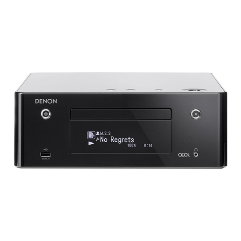
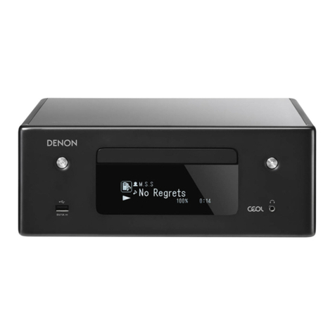
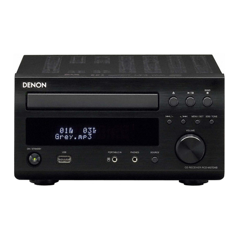
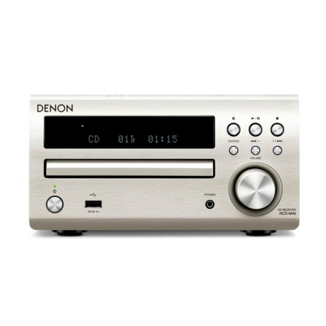
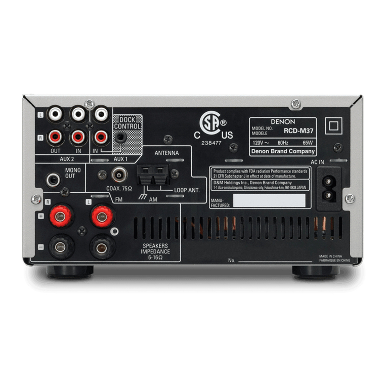
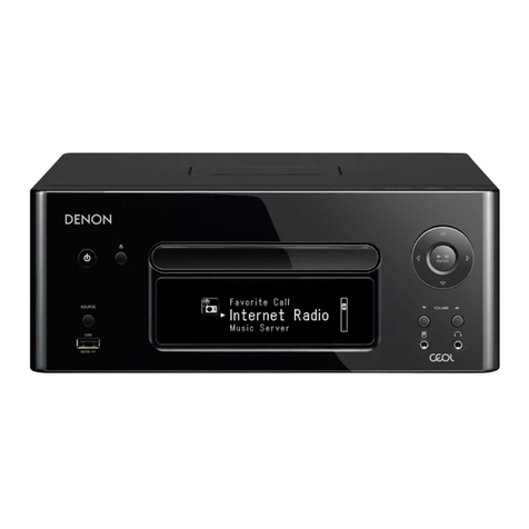
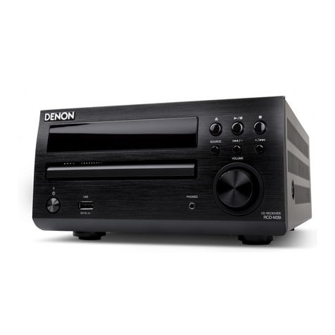
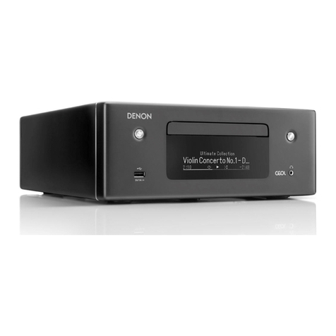
Denon RCD-M40 User manual

MODEL JP E3 E2 EK EA E1 E1C E1K
RCD-M40
P P P
RCD-M40DAB
P
D-M40S
P
CD RECEIVER
S1253V05DM/DG1605
Ver. 5
• Please use this service manual with referring to the operating instructions without fail.
• Some illustrations using in this service manual are slightly different from the actual set.
• For purposes of improvement, specications and design are subject to change without notice.
Please refer to the
MODIFICATION NOTICE.
e
SERVICE MANUAL
e
D&M Holdings Inc.
Copyright 2016 D&M Holdings Inc. All rights reserved.
WARNING: Violators will be prosecuted to the maximum extent possible.

ABOUT THIS MANUAL................................................................3
What you can do with this manual ...........................................3
Using Adobe Reader (Windows version)...................................4
SAFETY PRECAUTIONS...............................................................6
NOTE FOR SCHEMATIC DIAGRAM..............................................7
NOTE FOR PARTS LIST................................................................7
TECHNICAL SPECIFICATIONS.....................................................9
DIMENSION ..............................................................................10
CAUTION IN SERVICING ...........................................................11
Initializing This Unit.................................................................11
Support for Asia-Pacic tropical climate regions f................11
DISASSEMBLY ..........................................................................12
1. LOADER PANEL ASSY .........................................................14
2. FRONT PANEL ASSY............................................................14
3. CD MECHA ASSY ................................................................15
4. HEAT SINK SUB ASSY..........................................................15
5. POWER and CONNECT PCB ................................................16
6. MCU PCB............................................................................16
7. SPEAKER PCB......................................................................16
8. TRANS ................................................................................16
NOTES ON HANDLING AND REPLACEMENT OF THE LASER PICK-
UP.............................................................................................17
1. Protection of the LD...........................................................17
2. Precautions when handling the laser CD mechanism .......17
3. Cautions on assembling and adjustment ..........................17
4. Determining whether the laser pick-up is defective..........17
SPECIAL MODE.........................................................................18
Special mode setting button ..................................................18
1. Version Display Mode ........................................................19
2. Display check mode...........................................................19
3. Initialization (cold start) .....................................................19
4. CD test mode .....................................................................20
5. CD Heat run mode .............................................................23
6. Accumulated laser on time display mode..........................25
7. Updating MAIN u-COM......................................................25
8. Protection History Display Mode .......................................26
VERSION DISPLAY OF DAB MODULE (RCD-M40DAB only) g.27
PROCEDURE AFTER REPLACING THE MICROPROCESSOR, ETC.28
FIRMWARE UPDATE PROCEDURE............................................29
1. Updating via USB ...............................................................29
TROUBLE SHOOTING................................................................32
1. VFD is not lit .......................................................................32
2. No sound or noise is output...............................................33
MEASURING METHOD AND WAVEFORMS...............................38
1. DIGITAL PCB test point.......................................................38
2. INPUT PCB test point .........................................................39
3. WAVEFORMS......................................................................40
LEVEL DIAGRAM.......................................................................43
BLOCK DIAGRAM .....................................................................44
POWER DIAGRAM ....................................................................45
WIRING DIAGRAM....................................................................46
PRINTED WIRING BOARDS.......................................................47
SCHEMATIC DIAGRAMS (1/4)...................................................50
SCH01_DIGITAL MCU&CD.......................................................50
SCH02_DIGITAL-USB...............................................................51
SCH03_INPUT..........................................................................52
SCH04_MAIN...........................................................................53
EXPLODED VIEW f.................................................................54
PACKING VIEW .........................................................................55
SEMICONDUCTORS ..................................................................56
1. IC's......................................................................................56
2. FL DISPLAY.........................................................................76
CONTENTS
2

Jump to the target of a schematic
diagram connector
Click the Ref. No. of the target connector in the red
box around a schematic diagram connector.
•The screen jumps to the target connector.
•Pagemagnicationstaysthesameasbeforethe
jump.
CP401
CP106
v
ABOUT THIS MANUAL
Read the following information before using the service manual.
What you can do with this manual
Search for a Ref. No. (phrase)
(Ctrl+Shift+F)
You can use the search function in Acrobat Reader to
search for a Ref. No. in schematic diagrams, printed
wiring circuit diagrams, block diagrams, and parts
lists.
1.Press Ctrl+Shift+Fonthekeyboard.
• The Search window appears.
2.EntertheRef.No.youwanttosearchforinthe
Search window, and then click the Search button.
•A list of search results appears.
3.Click an item on the list.
• The screen jumps to the page for that item, and the
searchphraseisdisplayed.
Ctrl
Shift
F
3

Using Adobe Reader (Windows version)
• Properties
Click this button and check that the printer is set to a
suitable paper size.
• Page to print
Select the following checkbox.
"More Options" : "Current View"
• Page Sizing & Handling
Select the following checkbox.
"Size" / "Size Options" : "Fit"
Add notes to this data (Sign)
TheSignfunctionletsyouaddnotestothedatain
this manual.
Savetheleonceyouhavenishedaddingnotes.
[Example using Adobe Reader X]
On the "View" menu, click "Sign".
• The Sign pane appears.
[Example using Adobe Reader 9]
On the "Document" menu, click "Sign".
Magnify schematic / printed circuit
board diagrams - 1
(Ctrl+Space, mouse operation)
Press Ctrl+Spaceonthekeyboardanddragthe
mousetoselecttheareayouwanttoview.
• Theselectedareaismagnied.
• Whenyouwanttomovetheareashown,hold
down Space and drag the mouse.
• Whenyouwanttoshowafullpageview,press
Ctrl+0onthekeyboard.
Ctrl Space
0
Print a magnied part of the manual
ThePropertiesdialogboxandfunctionswillvarydependingonyourprinter.
1. Dragthemousetomagnifythepartyouwanttoprint.
2. On the "File" menu, click "Print".
3. CongurethefollowingsettingsinthePrintdialogbox.
4. Click the Print button to start printing.
4

Magnify schematic / printed circuit
board diagrams - 2
(Pan & Zoom function)
ThePan&Zoomfunctionletsyouseewhichpartof
amagnieddiagramisbeingshowninaseparate
window.
[Example using Adobe Reader X]
On the "View" menu, point to "Zoom", and then click
"Pan & Zoom".
• The Pan & Zoom window appears on the screen.
[Example using Adobe Reader 9]
On the "Tools" menu, point to "Select & Zoom", and
then click "Pan & Zoom Window".
Magnify schematic / printed circuit
board diagrams - 3
(Loupe Tool function)
TheLoupeToolfunctionletsyoumagnifyaspecic
part of a diagram in a separate window.
[Example using Adobe Reader X]
On the "View" menu, point to "Zoom", and then click
"Loupe Tool".
• The Loupe Tool window appears on the screen.
[Example using Adobe Reader 9]
On the "Tools" menu, point to "Select & Zoom", and
then click "Loupe Tool Window".
5

SAFETY PRECAUTIONS
The following items should be checked for continued protection of the customer and the service technician.
leakage current check
Beforereturningthesettothecustomer,besuretocarryouteither(1)aleakagecurrentcheckor(2)alinetochassis
resistance check. If the leakage current exceeds 0.5 milliamps, or if the resistance from chassis to either side of the
power cord is less than 460 kohms, the set is defective.
Be sure to test for leakage current with the AC plug in both polarities, in addition, when the set's power is in each state
(on,offandstandbymode),ifapplicable.
CAUTION Please heed the following cautions and instructions during servicing and
inspection.
◎Heed the cautions!
Cautions which are delicate in particular for servicing
are labeled on the cabinets, the parts and the chassis,
etc. Be sure to heed these cautions and the cautions
described in the handling instructions.
◎Cautions concerning electric shock!
(1) AnACvoltageisimpressedonthisset,soifyou
touch internal metal parts when the set is energized,
youmaygetanelectricshock.Avoidgettingan
electricshock,byusinganisolatingtransformer
and wearing gloves when servicing while the set is
energized,orbyunpluggingthepowercordwhen
replacing parts, for example.
(2) Therearehighvoltagepartsinside.Handlewith
extra care when the set is energized.
◎Caution concerning disassembly and
assembly!
Through great care is taken when parts were
manufacturedfromsheetmetal,theremaybeburrson
theedgesofparts.Theburrscouldcauseinjuryifngers
are moved across them in some rare cases. Wear gloves
toprotectyourhands.
◎Use only designated parts!
Theset'spartshavespecicsafetyproperties(re
resistance,voltageresistance,etc.).Besuretouseparts
which have the same properties for replacement. The
burrs have the same properties. In particular, for the
importantsafetypartsthatareindicatedbythezmark
on schematic diagrams and parts lists, be sure to use
the designated parts.
◎Be sure to mount parts and arrange the wires
as they were originally placed!
Forsafetyseasons,somepartsusetapes,tubesorother
insulatingmaterials,andsomepartsaremountedaway
from the surface of printed circuit boards. Care is also
takenwiththepositionsofthewiresbyarrangingthem
andusingclampstokeepthemawayfromheatingand
highvoltageparts,sobesuretoseteverythingbackas
itwasoriginallyplaced.
◎Make a safety check after servicing!
Check that all screws, parts and wires removed or
disconnected when servicing have been put back in their
original positions, check that no serviced parts have
deteriorate the area around. Then make an insulation
check on the external metal connectors and between
the blades of the power plug, and otherwise check that
safetyisensured.
(Insulationcheckprocedure)
Unplug the power cord from the power outlet, disconnect
the antenna, plugs, etc., and on the power. Using a 500V
insulation resistance tester, check that the insulation
resistancevaluebetweentheinplugandtheexternally
exposedmetalparts(antennaterminal,headphones
terminal,inputterminal,etc.)is1MΩorgreater.Ifitis
less, the set must be inspected and repaired.
Manyoftheelectricandthestructuralpartsusedinthe
sethavespecialsafetyproperties.Inmostcasesthese
propertiesaredifculttodistinguishbysight,andtheuse
ofreplacementpartswithhigherratings(ratedpower
andwithstandvoltage)doesnotnecessarilyguarantee
thatsafetyperformancewillbepreserved.Partswith
safetypropertiesareindicatedasshownbelowonthe
wiring diagrams and the parts list in this service manual.
Be sure to replace them with the parts which have the
designated part number.
(1) Schematicdiagrams.......Indicatedbythez mark.
(2) Partslists.......Indicatedbythezmark.
The use of parts other than the
designated parts could cause electric
shocks,resorotherdangerous
situations.
CAUTION Concerning important
safety parts
6
NOTE FOR SCHEMATIC DIAGRAM
WARNING:
Partsindicatedbythezmarkhavecriticalcharacteristics.UseONLYreplacementpartsrecommendedbythemanufacturer.
CAUTION:
Beforereturningthesettothecustomer,besuretocarryouteither(1)aleakagecurrentcheckor(2)alinetochassisresistancecheck.
If the leakage current exceeds 0.5 milliamps, or if the resistance from chassis to either side of the power cord is less than 460 kohms, the
set is defective.
WARNING:
DONOTreturnthesettothecustomerunlesstheproblemisidentiedandremedied.
NOTICE:
ALLRESISTANCEVALUESINOHM.k=1,000OHM/M=1,000,000OHM
ALLCAPACITANCEVALUESAREEXPRESSEDINMICROFARAD,UNLESSOTHERWISEINDICATED.PINDICATESMICRO-MICRO
FARAD.EACHVOLTAGEANDCURRENTAREMEASUREDATNOSIGNALINPUTCONDITION.CIRCUITANDPARTSARESUBJECT
TOCHANGEWITHOUTPRIORNOTICE.
NOTE FOR PARTS LIST
1.Partsindicatedby"nsp" on this table cannot be supplied.
2.Whenorderingapart,makeacleardistinctionbetween"1"and"I"(i)toavoidmis-supplying.
3.Apartorderedwithoutspecifyingitspartnumbercannotbesupplied.
4.Partindicatedby" ★" mark is not illustrated in the exploded view.
WARNING:Partsindicatedbythezmarkhavecriticalcharacteristics.UseONLYreplacementpartsrecommendedbythemanufacturer.
INSTRUCTIONS FOR HANDLING SEMI-CONDUCTORS AND OPTICAL UNIT
Electrostaticbreakdownofthesemi-conductorsoropticalpickupmayoccurduetoapotentialdifferencecausedby
electrostatic charge during unpacking or repair work.
1. GroundforHumanBody
Besuretowearagroundingband(1MΩ)thatisproperlygroundedtoremoveanystaticelectricitythatmaybe
chargedonthebody.
2. GroundforWorkbench
Besuretoplaceaconductivesheetorcopperplatewithpropergrounding(1MΩ)ontheworkbenchorothersurface,
wherethesemi-conductorsaretobeplaced.Becausethestaticelectricitychargeonclothingwillnotescapethrough
thebodygroundingband,becarefultoavoidcontactingsemi-conductorswithyourclothing
<Incorrect>
CBA
Grounding Band
Conductive Sheet or
Copper Plate
1MΩ
1MΩ
<Correct>
CBA
7

WARNING AND LASER SAFETY INSTRUCTIONS
FATTENTION
Tous les IC et beaucoup d’autres semi-
conducteurs sont sensibles aux décharges
statiques (ESD).
Leur longévité pourrait être considérablement
écourtée par le fait qu’aucune précaution
n’est prise a leur manipulation.
Lors de réparations, s’assurer de bien être
relié au même potentiel que la masse de
l’appareil et enfiler le bracelet serti d’une
résistance de sécurité.
Veiller a ce que les composants ainsi que les
outils que l’on utilise soient également a ce
potentiel.
DWARNUNG
Alle IC und viele andere Halbleiter sind
empfindlich gegen elektrostatische
Entladungen (ESD).
Unsorgfältige Behandlung bei der Reparatur
kann die Lebensdauer drastisch vermindern.
Sorgen sie dafür, das Sie im Reparaturfall
über ein Pulsarmband mit Widerstand mit
dem Massepotential des Gerätes verbunden
sind.
Halten Sie Bauteile und Hilfsmittel ebenfalls
auf diesem Potential.
WAARSCHUWING
Alle IC’s en vele andere halfgeleiders zijn
gevoelig voor elektrostatische ontladingen
(ESD).
Onzorgvuldig behandelen tijdens reparatie
kan de levensduur drastisch doen
verminderen.
Zorg ervoor dat u tijdens reparatie via een
polsband met weerstand verbonden bent met
hetzelfde potentiaal als de massa van het
apparaat.
Houd componenten en hulpmiddelen ook op
ditzelfde potentiaal.
AVVERTIMENTO
Tutti IC e parecchi semi-conduttori sono
sensibili alle scariche statiche (ESD).
La loro longevita potrebbe essere fortemente
ridatta in caso di non osservazione della piu
grande cauzione alla loro manipolazione.
Durante le riparazioni occorre quindi essere
collegato allo stesso potenziale che quello
della massa dell’apparecchio tramite un
braccialetto a resistenza.
Assicurarsi che i componenti e anche gli
utensili con quali si lavora siano anche a
questo potenziale.
All ICs and many other semi-conductors are
susceptible to electrostatic discharges (ESD).
Careless handling during repair can reduce
life drastically.
When repairing, make sure that you are
connected with the same potential as the
mass of the set via a wrist wrap with
resistance.
Keep components and tools also at this
potential.
WARNING
Safety regulations require that the set be restored to its original condition
and that parts which are identical with those specified be used.
Veiligheidsbepalingen vereisen, dat het apparaat in zijn oorspronkelijke
toestand wordt terug gebracht en dat onderdelen, identiek aan de
gespecifieerde worden toegepast.
Bei jeder Reparatur sind die geltenden Sicherheitsvorschriften zu beachten.
Der Originalzustand des Gerats darf nicht verandert werden.
Fur Reparaturen sind Original-Ersatzteile zu verwenden.
Le norme di sicurezza esigono che l’apparecchio venga rimesso nelle
condizioni originali e che siano utilizzati pezzi di ricambiago idetici a quelli
specificati.
Les normes de sécurité exigent que l’appareil soit remis a l’état d’origine et
que soient utilisées les pièces de rechange identiques à celles spécifiées.
“Pour votre sécurité, ces documents
doivent être utilisés par des
spécialistes agrées, seuls habilités à
réparer votre appareil en panne.”
GB NL
I
D
I
F
GB
NL
LASER SAFETY
CAUTION VISIBLE AND INVISIBLE LASER RADIATION WHEN OPEN AVOID EXPOSURE TO BEAM
ADVARSEL SYNLIG OG USYNLIG LASERSTRÅLING VED ÅBNING UNDGÅ UDS
Æ
TTELSE FOR STRÅLING
ADVARSEL SYNLIG OG USYNLIG LASERSTRÅLING NÅR DEKSEL Å PNES UNNGÅ EKSPONERING FOR STRÅLEN
VARNING SYNLIG OCH OSYNLIG LASERSTRÅLNING NÄR DENNA DEL ÄR ÖPPNAD BETRAKTA EJ STRÅLEN
VARO! AVATT AESSA OLET ALTTIINA NÄKYVÄLLE JA NÄKYMÄTTÖMÄLLE LASER SÄTEILYLLE. ÄLÄ KATSO SÄTEESEEN
VORSICHT SICHTBARE UND UNSICHTBARE LASERSTRAHLUNG WENN ABDECKUNG GEÖFFNET NICHT DEM STRAHL AUSSETSEN
DANGER VISIBLE AND INVISIBLE LASER RADIATION WHEN OPEN AVOID DIRECT EXPOSURE TO BEAM
ATTENTION RAYONNEMENT LASER VISIBLE ET INVISIBLE EN CAS D'OUVERTURE EXPOSITION DANGEREUSE AU FAISCEAU
USE OF CONTROLS OR ADJUSTMENTS OR PERFORMANCE OF PROCEDURE OTHER THAN THOSE
SPECIFIED HEREIN MAY RESULT IN HAZARDOUS RADIATION EXPOSURE.
AVOID DIRECT EXPOSURE TO BEAM
WARNING
The use of optical instruments with this product will increase eye hazard.
Repair handling should take place as much as possible with a disc loaded inside the player
WARNING LOCATION: INSIDE ON LASER COVERSHIELD
This unit employs a laser. Only a qualified service person should remove the cover or attempt to service this
device, due to possible eye injury.
030804ecm
8

TECHNICAL SPECIFICATIONS
nAudio section
• CD player
Playable frequency response:2 Hz - 20 kHz
Wow & utter:Below measurable limits (± 0.001 %)
Sampling frequency :
• Audio amplier
Rated output: 2-channel
30 W + 30 W (6 Ω, 1 kHz, T.H.D 10 %)
nTuner section
Receiving Range: F M 87.5 MHz - 107.9 MHz (for E3)
FM 87.5 MHz - 108.0 MHz (for E2, E1C)
FM 76.0 MHz - 95.0 MHz (for JP)
AM 520 kHz - 1710 kHz (for E3)
AM 522 kHz - 1629 kHz (for JP)
DAB 170 MHz - 240 MHz (for EK)
Usable sensitivity: FM 1.2 μV
AM 20μV
DAB 90 dBm / 50 Ω (for EK)
FM STEREO separation:35 dB (1 kHz)
nClock / Alarm / Sleep
Clock type:Crystal oscillator (Within 1 – 2 minutes per month)
Alarm:Once alarm / Everyday alarm : One system each
Sleep:Sleep timer : Max. 90 minutes
nGeneral
Power supply: (for E3): AC 120 V, 60 Hz
(for E2, EK): AC 230 V, 50 Hz / 60 Hz
(for E1C): AC 220 V, 50 Hz
(for JP): AC 100 V, 50 Hz / 60 Hz
Power consumption : 70 W
Power consumption in clock mode:14 W
Power consumption in standby mode:0.3 W
For purposes of improvement, specications and design are subject to
change without notice.
9

DIMENSION
Unit: in. (mm)
Weight: 9 lb 14 oz (4.0 kg)
199 2845
152
210
106.5
115
2929
30
27212 25
130
420
10

11
CAUTION IN SERVICING
Initializing This Unit
Make sure to initialize this unit after replacing the microcomputer or any peripheral equipment, or the digital PCB.
1. Press the power button to turn off the power, then unplug the power cord.
2. While holding down buttons the "8/-" and "SOURCE" buttons simultaneously, insert the AC plug to turn the
power on.
* The unit is initialized.
※ This unit can also be initialized by holding down the "8/-" and "SOURCE" buttons for at least three seconds while the
power is on.
Support for Asia-Pacic tropical climate regions f
Before selling this product, purchase and attach the tropical standard supporting part.
For this part, see the part list on TROPICAL sheet.
For where to attach the part, see the exploded view.
NOTE: • Initializing the device restores the customized settings to the factory settings. Write down your settings
in advance and recongure the settings after initialization.
8
/ -
Power operation (
X
) SOURCE
RCD-M40DAB

DISASSEMBLY
• Remove each part following the ow below.
• Reassemble the removed parts in the reverse order.
• Read "Precautions During Work" before reassembling the removed parts.
• If wire bundles are removed or moved during adjustment or part replacement, reshape the wires after completing
the work. Failure to shape the wires correctly may cause problems such as noise.
LOADER PANEL ASSY
See "DISASSEMBLY"
1. LOADER PANEL ASSY
and "EXPLODED VIEW"
LOADER PANEL
Ref. No. of EXPLODED VIEW : P 2
TOP COVER
FRONT PANEL ASSY
See "DISASSEMBLY"
2. FRONT PANEL SUB ASSY
and "EXPLODED VIEW"
FRONT PANEL PCB
Ref. No. of EXPLODED VIEW : C 1
SPEAKER PCB
See "DISASSEMBLY"
7. SPEAKER PCB
and "EXPLODED VIEW"
SPEAKER PCB
Ref. No. of EXPLODED VIEW : C 6a
MCU PCB
See "DISASSEMBLY"
6. MCU PCB
and "EXPLODED VIEW"
MCU PCB
Ref. No. of EXPLODED VIEW : C 11
HEAT SINK SUB ASSY
See "DISASSEMBLY"
4. HEAT SINK SUB ASSY
and "EXPLODED VIEW"
CONNECT PCB
Ref. No. of EXPLODED VIEW : C 2
AMP PCB
Ref. No. of EXPLODED VIEW : C 3
HEAT SINK
Ref. No. of EXPLODED VIEW : M 4
POWER and CONNECT PCB
See "DISASSEMBLY"
5. POWER and CONNECT PCB
and "EXPLODED VIEW"
POWER PCB
Ref. No. of EXPLODED VIEW : C 5a
CONNECT PCB
Ref. No. of EXPLODED VIEW : C 4
TRANS
See "DISASSEMBLY"
8. TRANS
and "EXPLODED VIEW"
TRANS
Ref. No. of EXPLODED VIEW : C 14
CD MECHA ASSY
See "DISASSEMBLY"
3. CD MECHA ASSY
and "EXPLODED VIEW"
DC-DC PCB
Ref. No. of EXPLODED VIEW : C 8
CD MECHA
Ref. No. of EXPLODED VIEW : C 16
12

Explanatory Photos for DISASSEMBLY
• For the shooting direction of each photos used in this manual, see the photo below.
• A, B, C and D in the photo below indicate the shooting directions of photos.
• The photographs with no shooting direction indicated were taken from the top of the unit.
• Photos of RCD-M40 E2 are used in this manual.
The viewpoint of each photograph
(Shooting direction:X)[View from the top]
Front side
Shooting
direction: D
Shooting
direction: C
↑Shooting direction: A↑
↓Shooting direction: B↓
13

1. LOADER PANEL ASSY
Proceeding : TOP COVER →LOADER PANEL ASSY
(1) Tray is opened and CD DOOR is removed.
2. FRONT PANEL ASSY
Proceeding : TOP COVER →LOADER PANEL ASSY →FRONT PANEL ASSY
(1) Remove the screws.
(2) Cut the wire clamps, then remove the connector wires. Remove the FFC.
View from the bottom View from the CD MECHA bottom
NOTE: Please remove slowly so as not to damage the hook of Tray and LOADER PANEL.
View from the bottomShooting direction: C Shooting direction: D
FFC
CN75
CN76
CUT
14

3. CD MECHA ASSY
Proceeding : TOP COVER →LOADER PANEL ASSY →FRONT PANEL ASSY →CD MECHA ASSY
(1) Remove the screws. Remove the connector wires.
Caution : Remove the FFC cable after the CD mecha's short circuit pattern for LD damage prevention has been short
circuited.
(2) Remove the FFC cable after the CD mecha's short circuit pattern for LD damage prevention has been short circuited.
Be sure to wear an earth band.
4. HEAT SINK SUB ASSY
Proceeding : TOP COVER →LOADER PANEL ASSY →FRONT PANEL ASSY →HEAT SINK SUB ASSY
(1) Remove the screws. Remove the connector wire.
Shooting direction: C
CUT
FFC
CN74
BN52
CN93 BN97
Caution
Soldering place
View from the bottom Shooting direction: D
STEP 1 STEP 2
CUT
CN95
CN71
BN73
CN72
15

5. POWER and CONNECT PCB
Proceeding : TOP COVER →LOADER PANEL ASSY →FRONT PANEL ASSY →HEAT SINK SUB ASSY
→POWER and CONNECT PCB
(1) Remove the screws. Remove the connector wires.
6. MCU PCB
Proceeding : TOP COVER →LOADER PANEL ASSY →FRONT PANEL ASSY →HEAT SINK SUB ASSY
→POWER and CONNECT PCB →MCU PCB
See "EXPLODED VIEW" for instructions on removing the MCU PCB.
7. SPEAKER PCB
Proceeding : TOP COVER →LOADER PANEL ASSY →FRONT PANEL ASSY →HEAT SINK SUB ASSY
→POWER and CONNECT PCB →SPEAKER PCB
See "EXPLODED VIEW" for instructions on removing the SPEAKER PCB.
8. TRANS
Proceeding : TOP COVER →LOADER PANEL ASSY →FRONT PANEL ASSY →HEAT SINK SUB ASSY
→POWER and CONNECT PCB →TRANS
See "EXPLODED VIEW" for instructions on removing the transformer (TRANS).
View from the bottom
Shooting direction: A
STEP 1
CW01
CW02
CN99
CN94
16

NOTES ON HANDLING AND REPLACEMENT OF THE LASER PICK-UP
1. Protection of the LD
Solder a part of the LD circuit to short-circuit. After connecting the circuit, remove the soldering form. Precautions when
handling the laser CD mechanism.
2. Precautions when handling the laser CD mechanism
• Be careful not to expose the laser pick-up to dust.
• Do not leave the laser pick-up bare. Be sure to cover it.
• If dust adheres on the laser pick-up lens, blow it off with a blower brush.
• Do not apply shock to the laser pick-up.
• Do not watch the light of the laser pick-up.
3. Cautions on assembling and adjustment
• Be sure that the bench, jig, head of soldering iron (with ceramic) and measuring instruments are well grounded.
• Workers who handle the laser pick-up must be grounded.
• The nished mechanism (prior to anchoring in the set) should be protected against static electricity and dust.
The mechanism must be stored where abnormal external force is not applied.
• When carrying the nished mechanism, hold it by the chassis body.
• Do not use or store the mechanism where corrosive gas such as H2S, SO2, NO2 and CI2 or toxic gas may be generat-
ed, or where substances especially organosilicon, cyanide, formalin and phenolic materials exist. In particular, make
sure that these substances which generate toxic gas do not exist in the set. This may cause the motor not rotating.
4. Determining whether the laser pick-up is defective
Cannot read discs, unsteady playback, etc.
Measure the RFO waveform of the MCU CD PCB and check the amplitude level.
(page 37 ② Measuring the RFO Waveform)
Between 0.4 and 1.1 (Vp-p)
Check the laser drive current (Iop)
(See "4.7 Displaying the laser current" in "4. CD test mode" for instructions on checking this.)
The present value is 1.5 times the default.
Replace the Traverse Unit
Store the laser current after replacement
Protective soldering place for laser diode.
NO
17

18
SPECIAL MODE
Special mode setting button
※ No.1 - 6, 8 : While holding down buttons "A" and "B" simultaneously, insert the AC plug into the wall outlet to turn on
the power.
※ No.7 : Perform this operation while the power is on.
No. Mode Button A Button B Descriptions
1 Version Display Mode 2 8/– Displays the version of rmware such as the main rm-
ware. (See page 19)
2 Display check mode 5 X Lights and unlights each segment repeatedly.
(See page 19)
3 Initialize (cold start) SOURCE 8/– Initializes the data. (See page 19)
4 CD test mode SOURCE XServo adjustment. Displaying the adjustment values and
laser current. (See page 20)
4-1 Disc mounting 5– For executing each CD mode.
4-2 Servo check 1/3– Checks each servo.
4-3 Pickup movement 8/– or +/9Moves the pickup to the inner or outer circumference.
4-4 Stop 2–Stops playback operations and servos and loads the
automatic adjustment values.
4-5 All servo on SOURCE – Turns all servos on and performs automatic adjustment.
4-6 Display adjustment values ↑ –
Displays the following adjustment values.
FOCUS BALANCE, FOCUS GAIN, TRACKING BALANCE,
TRACKING GAIN, FOCUS OFFSET, TRACKING OFFSET,
RFRP
4-7 Displaying the laser current 2– Indicates the present laser current.
5 CD heat Run mode 2+/9Executes each heat run mode.
(See page 23)
5-1 Normal heat run mode 1/3– Executes normal heat run mode.
5-2 Chucking mode 2– Executes chucking mode.
5-3 Error display – Displays the error code.
6 Accumulated laser on time display mode 2 X Indicates the accumulated laser on time.
(See page 25)
6-1 Resetting the count value 1/3– The setting values are initialized.
7 Update MAIN u-COM X 2 Updates the microprocessor.
(See page 25)
8 Protection history display mode SOURCE +/9Displays the protection occurrence history.
(See page 26)
8-1 Resetting the protection history 1/3– Resetting the protection history.
RCD-M40DAB
51
/
32
Power operation (
X
) SOURCE
9
/ +
8
/ -

19
1. Version Display Mode
(1) While holding down buttons the "2" and "8/–" buttons simultaneously, insert the AC plug to turn the power on.
(2) This unit cycles through 【MAIN u-COM Ver Display】 → 【USB u-COM Ver Display】 → 【MAIN u-COM Ver Display】 →・・・
each time the "SDB/TONE" button is pressed.
【MAIN u-COM Ver Display】
Ver 15030101vEK
【USB u-COM Ver Display】
U S B V E R
2 0 1 5 0 2 0 2 8 5
(3) To exit this mode, unplug the power cord.
2. Display check mode
(1) While holding down buttons the "X" and "5" buttons simultaneously, insert the AC plug to turn the power on.
(2) Lights and unlights all indicators at once in one-second intervals. Turns muting on.
(3) To exit this mode, unplug the power cord.
3. Initialization (cold start)
(1) While holding down buttons the "SOURCE" and "8/-" buttons simultaneously, insert the AC plug to turn the
power on.
This unit is initialized.
INITIALIZE
Default
SOURCE DISC
TUNER BAND FM ("DAB" on the DAB model)
SDB OFF
BASS 0
TREBLE 0
BLANCE CENTER
DIMMER 100%
VOLUME 5
TUNER PRESET frequency 0
Set -/+ PRESET -/+ button
Clock 00:00 Flashing (AM12:00 for E3)
ALARM SOURCE DISC
ALARM ON 00:00 (AM12:00 for E3)
ALARM OFF 00:00 (AM12:00 for E3)
SPK OPTIMISE ON
iPod MODE From iPod
CD Auto Play setting OFF
CLOCK MODE setting OFF
HP GAIN setting LOW
AUTO STANDBY E2/EK:ON
E3/JP/CN:OFF
DAB MODULE (EK) Initializes the module
※ Initial value of laser current and The accumulated laser on time are not cleared.
※ Power failure ag is not cleared.
(2) After initialization, the Unit returns to normal mode.

20
4. CD test mode
(1) While holding down buttons the "X" and "SOURCE" buttons simultaneously, insert the AC plug to turn the power
on.
"13"
0 0 C D T E S T M O D E
(
13 ashes)
(2) Return the slide to the default setting position (10mm from inner circumference).
(3) Perform the check by pressing the buttons. See 4.2 q ~4.2 y.
(4) Turn the power back on to cancel this mode.
※ Do not perform operations other than pressing the buttons that are intended to be used in this mode. (Otherwise,
this unit may not work properly.)
4.1. Disc mounting
(1) Press the "5" button to open the tray.
(2) Place the disc in the tray and press the "5" button again to close the tray and start disc chucking.
(3) Return the slide to the default setting position (10mm from inner circumference) and stop it in this position.
4.2. Servo check
Press "5" button. Execute the following steps.
Press and hold the "1/3" button continuously for over 1 second to skip to SUB CODE readout in step t.
q LD ON (while servo is stopped)
"13"
0 1 L D O N
(
13 ashes)
w FOCUS ON (disc rotating, tracking off)
z If there is no disc, the unit retries the operation and then stops.
"13"
02 Focus ON
(
13 ashes)
e CLV ON
"13"
03 CLV ON
(
13 ashes)
r TRACKING ON
"13"
04 Tracking ON
(
13 ashes)
t READ SUB CODE (playback sound output)
"13"
0 5 @ @
Tr
X X : X X
(
13 ashes / @@ : T.No / XX:XX : time)
y Press the "1/3" button while t is displayed to show the BER display for two seconds.
"13"
E R R # # # # # #
(
13 / #### : BER)
Other manuals for RCD-M40
4
This manual suits for next models
2
Table of contents
Other Denon Car Receiver manuals

Denon
Denon CEOL RCD-N9 User manual

Denon
Denon ceol RCD-N12DAB User manual

Denon
Denon D-T1 User manual

Denon
Denon D-M41DAB User manual

Denon
Denon DM40SBK User manual

Denon
Denon RCD-M39 User manual

Denon
Denon RCD-M33 User manual

Denon
Denon AVR-2311 User manual

Denon
Denon RCD-CX1 User manual

Denon
Denon UD-M31 User manual

Denon
Denon RCD-M40 User manual

Denon
Denon RCD-M33 User manual

Denon
Denon RCD-CX1 User manual

Denon
Denon RCD-CX1 User manual

Denon
Denon RCD-M40 User manual

Denon
Denon DCT-650 User manual

Denon
Denon CEOL RCD-N8 User manual

Denon
Denon DVD-3910 User manual

Denon
Denon RCD-N7 User manual

Denon
Denon RCD-M39 User manual