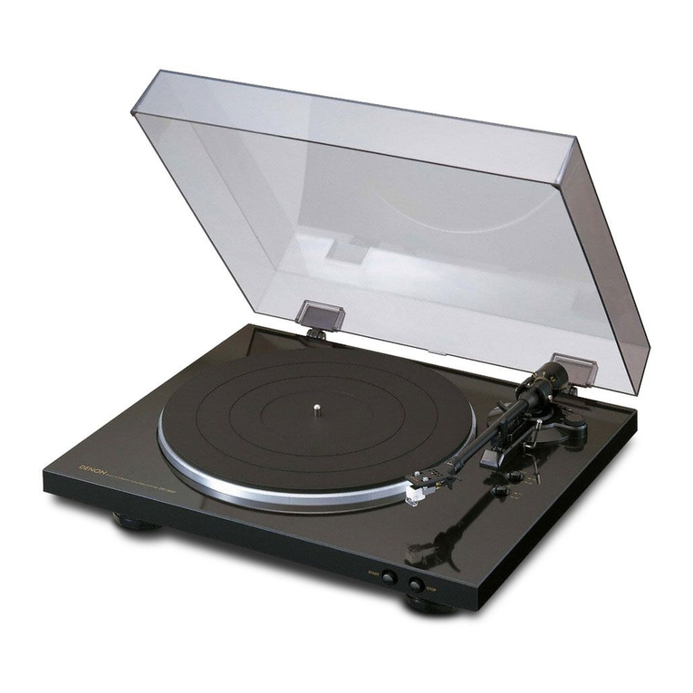
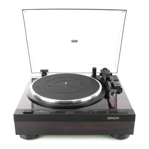
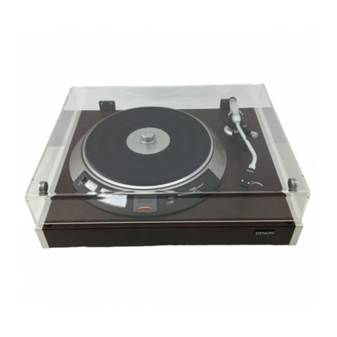
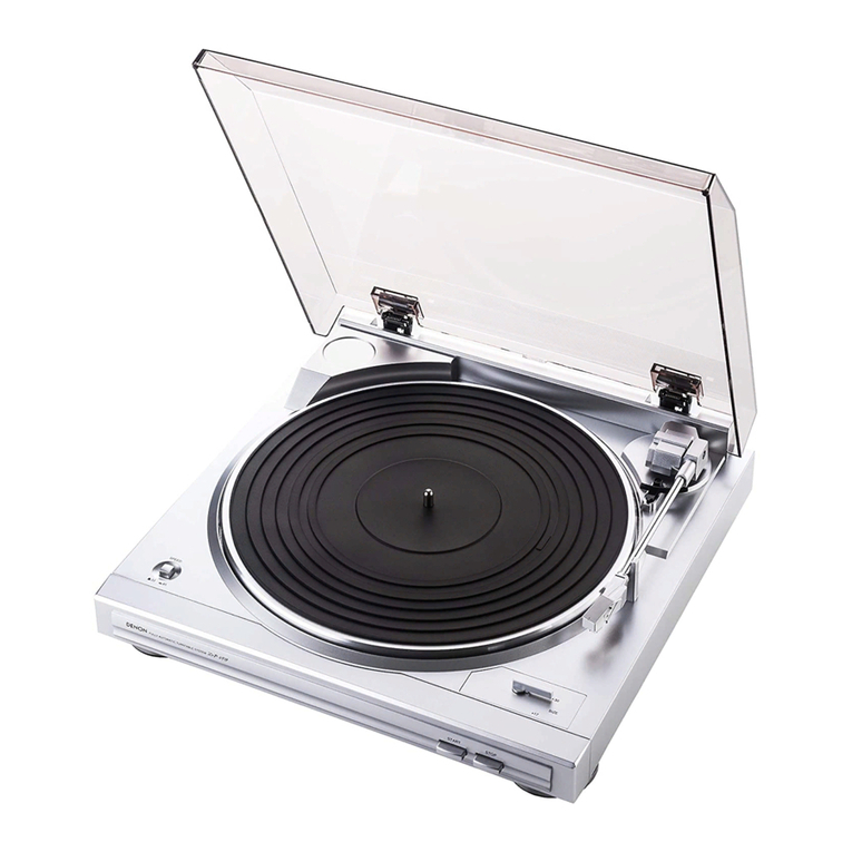
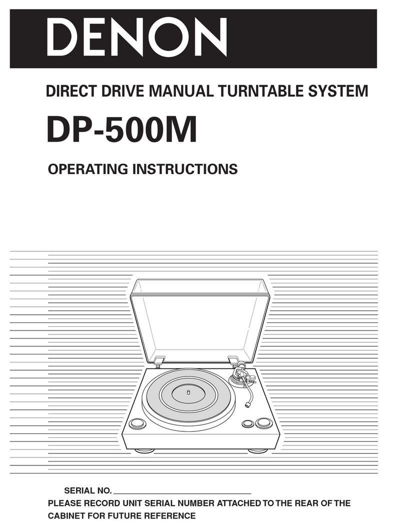
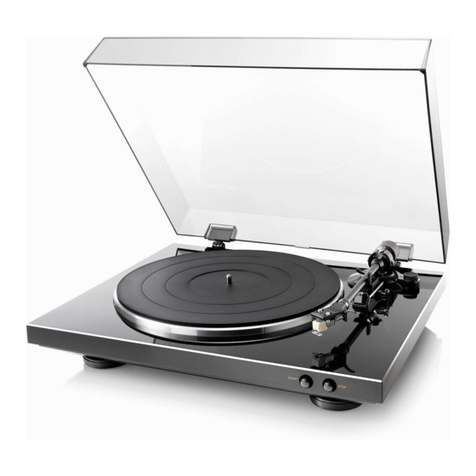
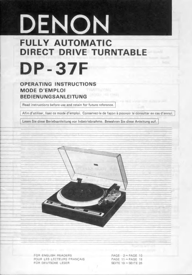
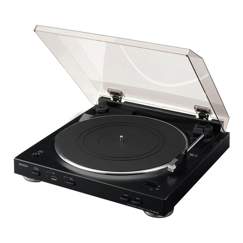
Denon DP-37F User manual

DENON
——
SERVICE
MANUAL
FULLY
AUTOMATIC
DIRECT
DRIVE
TURNTABLE
SYSTEM
MODEL
DP-37F
SERIES
U.S.
and
Canadian
models
do
not
inctude
cartridge.
NIPPON
COLUMBIA
CO,
LTD.

PEATURES:
ccna
sp
tasinaa
2
abatie-es
gereteleaiis
eligi
dt
avatdgdvana
es
ayaGelebiviaiate
Meatecalat
an
2
SPECIFICATIONS
.........
Se
deersis
ee
be
Misch
aegis
i
aol
data
3
BLOCK
DIAGRAM
..........-.0055
Aes
nae
Mea
Reet:
ee
setaes
4
PART
NAMES
AND
EUNCTION
222
c-teaunee
caine
waa
cedar
naald
cues
5
ADJUSTMENT
METHOD
.......
ES
Te
ene
ne
er
eT
a.
6Y?
EXPLANATION
HOW
THE
LSI
QUARTZ
. .
PLL
MOTOR
CONTROL
OPERATES
.......cccccsecsccevevsseeeueens
8
PARTS
LIST
OF
PW.
BOARD
........ccccccceccenvecucevecevecenanes
2)
PARTS
LIST
OF
EXPLODED
VIEW
......cccccccccecceneseeeeueues
veer.
10
EXPLODED
VIEW
<simoviis
ceveandsalewsestenedewn
ches
aa
ROS
erate
nindes
os
SCHEMA
TIC:
DIAGRAM
26c.cc
seems
tie
vie
bbw
core
erin
eineked
thaw
eee
12
CONNECTIONS
OF
PW:
BOARD
=
0ix.k
codon
dated
daend(hiGeie
oiwerns
13
P.W.
BOARD
OF
KU-5260
SERVO
CONTROL
UNIT
oo...
cece
cece
eee
ees
14
P.W.
BOARD
OF
KU-5014
MOTOR
DRIVE
UNIT
........cceeescesaneens
15
FEATURES
Microprocessor
controlled,
contactless
servo
tonearm
A
unique
microprocessor
controlled,
contactless
servo
tonearm
ensures
safe,
easy
to
use
automatic
operation
with
no
deterioration
in
sound
quality.
Q-damping
method
(Dynamic
servo
tracer)
Low
frequency
resonance
caused
by
the
cartridge
compliance
and
the
effective
tonearm
mass
is
elec-
tronically
damped
both
horizontally
and
vertically
.
to
effectively
suppress
crosstalk:
and
inter-modula-
tion
distortion.
The
dynamic
servo
tracer
maximizes
the
performance
of
the
low
mass
tonearn’
and.
results
in
a
record
reproduction
of
excellent
sound
image
with
minimum
noise
and
distortion,
Low
mass
straight
arm
ae
Having
an
outstanding
tracing
ability,
this
arm
maxi-
mizes
the
performance
of
the
high
compliance
car-
Even
with
the
most
up-to-
tridge
to
the
full
extent.
date
high
grade
records,
its
tracing
ability
is
excellent.
4,
DENON
quartz
on
bi-directional
servo
The
ultimate
in
rotational
accuracy
is
realized
by
the
combination
of
a
magnetic
pulse
detector
and
a
quartz
lock,
with
the
addition
of
a
bi-directional
servo.
Newly
developed
cartridge
The
low
mass
MM
type
cartridge
DL-65
with
an
elliptically:
shaped
stylus
minimizes
tracing
distortion
anc
contributes-to
the
clarity
of
the
reproduced
sound,
Newly
developed
cartridge
(European
model
only)
A
high
output
.MC
-cartridge
with
an
output
voltage
comparable
to
MM
cartridges.
The
Di-710
is
a
high
output
MC
cartridge
which
can
be
connected
directly
to
the
MM
position
of
the
am-
plifier
without
step-up
transformers
or
head
amplifiers.
Note:
U.S.
&
Canadian
models
do
not
include
car-
tridge.
SPECIFICATIONS
Parts
marked
with
A\
and/or
shading
in
this
service
manual
have
special
characteristics
important
to
:
-
safety.
Be
sure
to
use
the
specified
parts
for
replacement.
®
Phono
motor
section
Drive
system
:
Servo
controlled
direct
drive
Turntable
speeds
:
33-1/3,
45
rpm
Wow
&
Flutter
:
Below
0.012%
wrms
(servo
system)
:
Below
0.02%
wrms
(J1S}
S/N
ratio
:
Over
78
dB
{DIN-B}
g
Rise
time
:
Normai
speed
within
2
seconds
(at
33-1/3
rpm)
Turntable
platter:
Aluminum
die-cast;
300
mm
diameter
Motor
:
Linear
drive
motor
:
:
Speed
control
system
:
Speed
servo
by
frequency
detection
and
phase
servo
contro!
Speed
deviation
:
Below
0.01%
Load
characteristics
:
0%
(80
g
stylus
force;
outermost
groove}
e
Tonearm
section
Arm
type:
Dynamicaily
balanced,
straight
tube
tonearm
Effective
length
:
220
mm
Overhang
:
16mm
Tracking
error
:
Within
3°
Automatic
mechanism
:
Electronically
controlled,
fully
automatic
Adjustable
stylus
force
range
:
Q~
3.0
g
(1
scale=0.1
g)
Suitable
cartridge
weight
range
:
Approximately
4.0
~
9.0
g
{including
screws,
nuts)
®
Cartridge
section
:
Made!
:
{Asian
model)
{Europian
model}
DL:65
DL-110M
Type:
Moving
magnet
(MM)
Moving
coil
(MC)
Output
voltage
:
2.5mV
;
1.6mV
Frequency
response
:
20 Hz
~
30
kHz
20
Hz
~
45
kHz
Tracking
force
;
1840.3g
1.84039
e
General
Power
supply
:
50/60
Hz,
Voltage
is
shown
on
rating
label
Power
consumption
:
Approx,
8W
:
Demensions
:
434
(W)
x
145
(H)
x
410
(D)
mm
17
(W)
x
5.7
{H)
x
16.1
(BD)
in
:
Weight
:
Approx.
7.0
kg
Approx.
15
|b
_
U.S.
and
Canadian
models
do
not
include
cartridge.
Above
specifications
and
outward
appearance
may
be
altered
in
future
for
improvement.
'
WARNING:
1.
Component
parts
:
2.
Leakage
current
Before
returning
the
appliance
to
customer,
test
the
leakage
current
when
the
power
plug
is
connected,
Use
a
calibrated
(with
an
errer
of
not
more
than
5%}
leakage
current
tester
and
measure
the
leakage
current
from
any
exposed
metal
to
the
earth
ground.
Reverse
the
power
plug
polarity
and
test
the
above
again.
Any
current
measured
MUST
NOT
EXCEED
0.5
milliamps.
Corrective
measure
must
be
taken
if it
exceeds
the
limit.
;

|
BLOCK
DIAGRAM
“
Lock
indication
“Gy
feF,
Speed
selector
(33/45)
—aaas
Start
o
6
Stop
Repeat
Lifter
Size
s@lector
sat_—
{30/47}
Oo
0
Anti
skate
and
Tracking
force
adjust:
ment
Rotational
speed
detection
FG
Phonomotor
Amplifier
Quartz
PLL
Motor
contro!
LST
Maror
(M)<
i
TC
9142
Memorize
START/STOP
command
Speed
detection
Up/Down
command
ry
QO
damping
‘
Bs
+
Power
Ofori
3
n-
+
Vertical
motar
-
Arm
contrat
microprocessor
IR3TO3
{Lifter
mator}
Rest/End
:
Position
Compera
;
amptifier
4)
Memorize.
+
Horizontai
-
killer
com-
Acceleration
mand
input
Acceleration
+
Output
Compare’
amplify
17/30
Position
detection
Amplify
re
Power
Amplifier
|
oe
&
(M)
+
i
%
Q,
damping
Horizontal
motot
Speed
detection

iPART
NAMES
AND
FUNCTION
|
Power
switch
POWER
This
turns
the
power
supply
on
and
off,
Push
the
but-
ton
down
until
it
locks.
When
turning
the
power
off,
press
the
button
until
the
lock
is
disengaged.
Be
sure
to
return
the
tonearm
to
the
arm
rest
and
hold
it
in
with
the
clamp.
Record
size
selector
switch
SIZE
Before
playing.a
record,
press
the
button
correspond-
ing
to
its
record
size,
For
30
cm
(12
inch)
records,
the
(30}
indicator
will
light.
For
17
cm
(7
inch)
records,
the
(17)
indicator
will
light.
Speed
selector
switch
SPEED
Before
playing
a
record,
press
the
button
correspond-
ing
to
its
record
speed.
The
(33)
indicator
will
fight
for
33
1/3
rom
records.
The
(45}
indicator
will
light
for
45
rpm
records.
Lock
indicator
LOCK
The
lamp
wili
light
when
the
turntable
reaches
a
nominal
rpm.
speed
in
the
Piay
mode.
10
UP-LIFTER
Arm
lifter
switch.
Press
this
button
to
raise
or
lower
the
tonearm
during
play,
or
when
playing
records
manually.
The
“UP”
indicator
will
light
up.
Repeat
switch
REPEAT-ON
Press
this
button
for
playing
the
same
record
repeated-
ly
the
“ON”
indicator
will
light
up.
Start
switch
START
Press
this.
button
to
start
records
automatically.
Stop.
switch
STOP
Press
this
button
to
stop
a
record
during
piay.
Tracking
force
adjustment
knob
=
TRACKING
This
knob
is
used
to
adjust
the
tracking
force
and
anti-skating
amount.
;
Q-damping
adjustment
knob.
Q-DAMPING

ADJUSTMENT
METHOD
e
PHONO
MOTOR
ADJUSTMENT
1}
2}
3)
4)
5)
8)
7)
8)
9)
2.
1)
2)
3)
Off-set
adjustment
Set
the
X-asis
and
Y-axis
sensitivity
of
the
oscilloscope
to
100mV/cm
by
using
a
10:1
probe.
Connect
the
X-axis
terminal
of
the
probe
with
TP-203
on
the
motor
drive
base
beard
and
the
Y-axis
terminal
of
the
probe
with
TP-204,
Use
pin
No.
8
as
the
ground.
Connect
pin
No.
5
and
pin
No.
8
and
make
a
low
resistance
circuit
on
the
input
terminal.
Stop
the
rotor
at
the
maximum
position
of
the
X-axis
amplitude
of
the
Lissajous’
figure
of
the
oscilloscope
while
turning
the
motor
by
hand,
Set
the
maximum
amplitude
at
the
X-axis
by
adjusting
VR-201.
A=A'
Stop
the
rotor
at
the
maximum
position
of
the
Y-axis
amplitude
of
the
Lissajous’
figure.
7
Set
the
maximum
amplitude
at
the
Y-axis
by
adjusting
VR-202.
B
=B’
Adjust
the
center
of
the
circle
to
+
5OmvV.
Y-axis
4+,
.(100mV}
:
{100mvV)
X-axis
eo
Disconnect
pin
No.
5
and
pin
No.
8
after
adjustment.
Amplitude
adjustment
-
Check
the
X-axis
and
Y-axis
sensitivity
of
the
oscillo-
scope
by
using
£
5V
power
supply.
Remove
the
arm
from
the
arm
rest
and
remove
the
turntable.
Then,
turn
the
motor
with
full
speed.
Set
the
amplitude
of
the
X-axis
and
Y-axis
of
the
Lissajous’
figure
te
15
VP-P
by
adjusting
VR-203
and
VR-204.
Make
sure
that
there
is
no
voltage
difference
between
the
X-axis
and
the
Y-axis..
isveP
1pyPP
.
Center
adjustment
+)
Adjust
the
X-axis
and
Y-axis
sensitivity
of
the
oscillo-
scope
to
2V/cm,
2)
Set
the
amplitude
of
the
X-axis
and
Y-axis
of
the
Lissajous’
figure
to
exactly
the
same
point
from
the
center
by
adjusting
VR-205
and
VR-206.
After
the
adjustment,
the
amplitude
should
be
as
shown
in
the
figure
below,
Figure
7.6V+0,4V
4.
Adjusting
the
head
gap
Adjust,
so
that
the
gap
between
the
turntable
magnetic
coating
surface
and
the
detection
head
is
0.18
mm.
5.
Checking
the
33
r.p.m.
and
45
r.p.m.
locks
From
now
on,
use
test
point
TP-1
of
the
servo
control
circuit
board
as
the
earth
reference
point
of
the
measuring
instrument.
1)
Connect
an
oscilloscope
to
test
point
TP-6.
2)
Make
sure
to
check
that
the
voltage
of
TP-6
at
normal
speed
is
approximately
2.2
V,
, :
Vang
=
22V

e
ADJUSTING
THE
ARM
CONTROL
SECTION
Lead-in
adjustment
hole
VR-5
(Tracking
force
adjustment)
VR-3
(Horizontal
offset
.
voltage
adjustment)
VR-4
(Lifter
offset
voltage
adjustment}
2}
3)
2.
3)
2)
3)
3.
1)
2)
3)
4)
5)
4.
1)
2)
Adjusting
the
horizontal
OP
amp,
offset
voltage
Fix
the
tonearm
to
the
arm
rest
and
connect
the
oscil-
loscope
to
TP-3.
Set the
lifter
switch
to
the
UP
condition.
Turn
VR-3
and
adjust
to
OVt0.01V.
.
Adjusting
the
lifter
OP
amp.
offset
voltage
Fix the
tonearm
to
the
arm
rest
anc
connect
the
oscil-
lascope
to
TP-4.
Set
the
liter
switch
to
the
DOWN
condition,
After
about
7
seconds,
adjust
to
OV+0.07V
by
turning
VR-4.
Adjusting
the
tracking
force
Turn
the
power
supply
switch
OFF.
Take
the
arm
off
the
arm
rest,
Rotate
the
balance
weight
so
that
the
tonearm
becomes
parallel
to
the
turntable
surface
when
let
go.
Return
the
arm
to
the
arm
rest
and
turn
the
power
supply
switch
ON.
Wait
seven
seconds
after
the
arm
has
lowered,
Place
the
cartridge
stylus
tip
onto
a
stylus
force
gauge
and
set
the
tracking
force
adjustment
knob
to
1.89.
{Note}
At
this
time,
the
stylus
tip
height
should
be
adjusted
so
that
it is
about
the
same
height
as
during
play.
Turn
VR-5
and
adjust,
so
that
the
stylus
force
gauge
reads
1.8g.
(Turn
VR
slows.}
Adjusting
the
30
cm
fead-in
position
Place
a
30
cm
record
on
the
turntable
and
set
the
record
dize
selector
switch
to
“30”.
(Note}
Keep
the
bottom
cover
closed.
Move
the
arm
so
that
the
stylus
tip
is
at
approximately
the
30
cm
lead-in
Position.
Insert
a
small
flat-headed
screwdriver
into
the
fead-in
adjustment
hole;
move
the
arm
back
and
forth
and
fit
the
screw
driver
into
the
groove
of
the
cam
inside
gently.
3)
5.
After
turning
the
screwdriver,
pull
it
out
once.
Press
the
start
switch
and
adjust
so
that
the
stylus
position
stops
at
the
30
cm
head-in
position.
{Note}
The
30
cm
head-in
adjustments
cannot
be
per-
formed
unless
the
stylus
tip
position
is
approximately
in
the
30
cm
lead-in
position.
In
addition,
if
the
screw-
driver
is
left
inserted,
the
arm
will
rot
move.
Adjusting
the
17
cm
lead-in
position
Adjust
as
necessary,
such
as
when
parts
of
the
sensor
sec-
tion
have
been
replaced.
However,
the
following
procedures
should
only
be
died
when
a
discrepancy
is
found
for the
17
cm
!ead-in
position,
after
the
30
cm
lead-in
position
has
been
adjusted.
1)
2}
3)
4)
5)
Set
the
record
size
selector
to
17
cm.
By
continuously
pressing
the
start
switch,
the
arm
will
move
over
and
stop.
At
this
time,
check
now
many
millimeters,
toward
the
inside
or
outside,
the
stylus
tip
deviates
from
the
required
17
cm
lead-in
position,
Take
off
the
bottom
cover
of
the
cabinet
and
check
the
adjustment
scale
position
of
the
shutter.
{One
adjustment
scale
corresponds
to
a
stylus
tip
movement
of
0.5
mm.)
Untighten
the
screw
holding
the
sub
shutter
and
place
a
small
flat-headed
screwdriver
into
the
slot
of
the
shutter.
When
the
sty!us
position
is
taward
the
inside,
“sompared
to
the
required
position,
move
the
sub:
shutter
toward
the
right
of
the
scale;
when
the
stylus
position
is
toward
the
outside,
move
the sub
shutter
toward
the
left.
When
completed,
tentatively
tighten
the
screw
holding
the
sub
shutter,
After
the
adjustments
are
made,
press
the
start
switch
and
check
whether
or
not
the
stylus
stops
at
the
17
cm
lead-in
position.
;
If
the
stylus
stops
at
the
required
position,
then
tighten
the
sub
shutter
screw.
Screwdriver
Shutter
Sub
shutter
Stopper
Sub
shutter
screw

EXPLANATION
HOW
THE
LS!
QUARTZ
PLL
MOTOR
CONTROL
OPERATES
©
LSI
motor
control
...
TC9142P.
{33
r.p.m,
is
set
as
the
standard
speed)
©
Due
to
C-MOS
construction,
handle
this
IC
with
ex-
treme
care.
O
Vin
(min)
..0.7
x
Veo
=3.6V
©
Vy
(max.)..,0.3
x
Vee
=
1.5V
©
In
terminals
4,
5,
10,
and
11,
pull-up
resistors
are
built
in,
Terminal
1
:
GND
Terminal
2
:
OSC
OUT
(7.68
MHz)
O13
us”
Terminal
3
:
OSC
IN
(7.68
MHz)
_
Terminal
4
+
Internal
frequency
divider
ratio
switch
and5
Terminals
4
and
5
determine
the
frequency
dividing
ratio
of
the
internal
frequency
divider,
Terminal
6
:
FG
input
T=
1.8
ms
(33
rpm)
=
7.33
ms
(45
rpm)
APC
output
(TP-6)
Phase
control
system
output
of
the
motor
Terminal
7
:
Same
in
either
33
rpm
or
45
rpm
Terminal
8
:
Terminal
10:
Terminal
71
Terminal
42:
Terminal
14:
Terminal
15:
Terminal
16:
AFC
output
Speed
(frequency)
control
system
output
of
the
motor
Same
in
either
33
rpm
or
45
rpm
33/45
rpm
switch
input
L
...
33-1/3
rpm
H,,,
45
rpm
:
PLAY/STOP
input
L
...
PLAY
H
...
STOP
Lock
detector
output
Within
locking
range...
H
| ~
Outside
locking
range
...
L
Reference
frequency
input
(CR
IN)
Connected
to
terminal
15
Reference
frequency
output
{CP
OUT}
In
accordance
with
the
ratio
set
by
terminals
4
and
5,
the
divided
frequency
output
is
obtained,
.
a
7.68
x
10°
+4
=
1.92
MHz
(center
value}
{When
terminal
4:
H
and
terminal
5:
L)
Line
voltage
{Vcc}
Veco:
5V
40.25
V

PARTS
LIST
OF
P.W.
BOARD
KU-5260
SERVO
CONTROL
UNIT
SEMICONDUCTOR
GROUP
IC4,
5
2620057004
|
HD7473P
icg
2620276005
|
HD14066BP
Ic}
2630271003
|
TC9142P
12
2630174003
|
IR3TO3
IC3,
8
2630257001
|
M-5218P
1C6,
12
2630237005
|
LA6358
107
2630198005
|
NuM4556D
iC10
2630147001
|
pPC78MO5H
Ici
2630160004
|
uPC7905H
TR3,8
2710102005
|
2SA1015{Y)
TR1,2
2730198002
|2SC1815(Y)
4~7
9~15
1~5
2760049008
|
1s2076
410~17
p6~9
2760237001
|
RVOG
THI
2760311008
|
THERMISTOR
(1K2)
LEDI~6
3939219008
|
GL-5EG23
LED?7~9
3939041001
|
LNS1RP-HL.
:
CDS1,
2
3939053002
|
CDS
cDs3
3939053028
|
CDS
(10-15Kn}
RESISTOR
GROUP
Carbon
fiim
R15
2410173004
|
RO14B2H331J
3302
AW
Variable
resistor
VR1,2
2118024015
|
VI6V20K
8502
5KQB
2116000073
|
VO8PB203
20K28
CAPACITOR
GROUP
Ceramic
C15,
18,19
|
2531004007
1000PF
21,
24,
27
3,
50
C4,
8,
32
35,
36,
38
40,
42,
44
51,
101,
102
107,
108
cto,
11
C12
|
C53,
57
c1,5
54.
a
CK45B1H102K
50V
2531027000
|
CK45F1H1042Z
O1nF
50V
2533603008
2532611003
2533627000
2533637003
10PF
22PF
JOOPF
270PF
CC45SL1H100D
CC45SL1H220J
CC45SL1H101J
CC45SL1H271J
50V
.
50V
50V
50V
Electrolytic
C5
O.47uF
50V
103,
117
C2,3,6
14,
17,
20
23,
59,
60
113
C7,
16,
26
33,
37,
48
2544145005
|
CEQ4W1HR47=
2544146004
|
CEO4W1HO10=
1pF
-
50V
2544132005
|
CEO4W1CT00=
25441
28006
CEO4W1A220=
22uF
10V
C30
2544129005
|
CEOD4W1A470=
47uF
0
10V
C29,
31
2544130007
|
CEQ4wic101=
100uF
16V
34,
63
C45
2544080005
|
CE04W=1E102M
1000unF
25V
C43
2544086009
|
CE04W1E222M
2200uF
25V
;
Film
C46,
47
2551072006
|
CO93M1H103K
0.01uF
SOV
58,
105
C61
2551121025
|
CO93M1H103J
O.0inF
50V
C13
2557121096
|
CQS3M1TH393J
'
0.039uF
SOV
ch2
2551122008
|
CQ93M1H473J
0.047uF
50V
C55,
116
2551122024
|
CQ93M1H683J
0.068uF
50V
OTHER
PARTS
GROUP
2129218001
|
TACT
SW
2129180003
|
PUSH
SW
:
3998037001
|
CRYSTAL
7.68
MHZ
4178028101
|
HEAT
SINK
4428030108
|
VOLUME
“~BRACKET-
SWITCH
BRACKET
LED
HOLDER
LED
HOLDER
4428164003
4438811207
4438568107
@
The
carbon.
resistors
rated
at
“W
are
not
listed
herein,
KU-5014
MOTOR
DRIVE
UNIT
Ref.
No.
Part
No,
Part
Name
SEMICONDUCTOR
GROUP
1C201
H201,
202
TR202,204
TR201
,203
D207,
203
FH201,202
2630257001
2680042004
2710105002
2730201009
2760049008
276031
1008
M52718P
H-300A
2SA966
(Y}
28C2236
(Y}
182076
THERMISTOR
(1KQ)}|.
RESISTOR
GROUP
VR203,204
|
2116000031
VR201
,202
|
2116060073
VO8PB
102
(1K)
VOS8PB203
(20K22)
205,
206
|
CAPACITOR
GROUP
C205
2531027000
|
CK45F1H104Z
O.inF
50V
C202.
2544075008
|
CEO4W1C100=
©
10uF
16V
C203,
204
|
2551072006
|
CO93M7H103K
O.01nF
50V
#
The
carbon
resistors
rated
at
%W
are
not
listed
herein.
Remarks
symbols
in
the
parts
list
refer
to
the
following
countries
and
areas.
;
:
EA:
Australia
E1:
Multiple
voltage
model
EK:
United
Kingdom
E2:
European
continent
EU:
U.S.A,
EC:
Canada

PARTS
LIST
OF
EXPLODED
VIEW
ce
ese
Te]
129801
ssl
Seatac
RU!
ee
AS
Soucageane
ee
+
|
4713303016
|
3x6
CBS
Ee
2
|
4711303018
|
3x6
CPS
3
|
4751003006
|
3W
SR5A07
z
s
4
|
4438545201
|
COLLER
1018416300
CABINET
ASS'Y
5
|
4638225004
|
SPRING
.
55
|
4148201000
|
SHEET
6
|
4711810019
|
2x3
CPS
,
56
|
1038268302
|
CONTROL
FRAME
7
|
4338241100
|
SHUTTER
57
|
1038280109
|
PANEL
FRAME
@
|
3418025208
|
MAGNET
ASS'Y
58
|
1468151118
|
DUST
COVER
ASS'Y
g
|
4761003009
|
3E
RING
59
|
462802300
|
BUSHING
10
4751005004
AW
AO
eee
cue
11
|
3158451003
|
FRICTION
WASHER
ABE
eas
el
42
|
4249019202
|
ADJUST
CAM
é
43
|
4733808012
|
3x12
CBTS
(1)
ANE
44
|
2398013215
]
COIL
ASS'Y
15
|
4338175108
|
YOKE
{A}
ASS'Y
46
|
3158712108
]
LATERAL
WEIGHT
47
|
4744304000
|
3x3
BSS
(D}
Ue
B00
ee
48
|
4730306012
}
3x12
CBRTS
(1)
63
|
EP-7376
CORD
BUSH
19
|
4428030108
|
VOLUME
BRACKET
64
|
2033642103
|
OUTPUT
CORD
ASS'Y
29
|
1128085029
|
VOLUME
KNOB
2021640000
|
OUTPUT
CORD
ASS‘Y}
EU
only
21
|
4756133007
|
14N
65
|
4338243001
|
SUB
SHUTTER.
22
|
3158896215
|
TONE
ARM
ASS’Y
: ;
66
|
4733811009
|
3x25
CBRTS
(2)
23
|
3158899018
|
BALANCE
WEIGHT
67
|
4428164003
|
SWITCH
BRACKET
ASS'Y
63
|
1138186002
|
KNOB
24
|
3158553037
|
HEAD
SHELL
ASS'Y
g9
|
4318086000
|
FRICTION
SHEET
25
|
DL006s
BICK
UP
CARTRIDGE
|
EA,
EK,&1
71
|
3158911116
|
ARM
REST
ASS'Y
DL-110M
PICK
UP
CARTRIDGE
|
E2
|
72!
Ep.a772
CORD
HOLDER
26
|
4713808003
|
3x25
CBS
73
|
4438812001
|
SPACER
27
|
4731806003
|
3x20
CPTS
(1)
74
|
4148181007
|
SHILD
SHEET
98
|
2178081030
|
MOTOR
ASSY
75
|
4712306014
|
3x12
CFS
29
|
KU-5060*1
|
OUTPUT
P.C.B.
|
76
eee
3x8
cBRTS
a)
30
|
KU-6060*2
|
LEAD
IN
LED
P.C.B.
. .
ALBEE
:
E:
a
‘Gs
SECTOR
Ame
31
|
4730355018
|
3x10
CBRTS
79
|
4730204017
oma
CRTs
(u
39
|
4419846014
|
WASHER
33
|
4418163101
|
HEAD
SUPPORT
WARNING:
34
|
3918423006
|
MAGNETIC
HEAD
Parts
marked
with
/X
and/or
shading
have
special
characterist:
35
|
4700009019
3x6
CPS.
W
important
to
sefety.
Re
sure
to
use
the
specified
parts
for
repiace-
36
|
4730309019
|
3x16
CBRTS
(1)
ment:
37
|
1468167209
|
FRAME
ASS’Y
£2,
EA,
EU,
EC,
EK
PACKING
AND
ACCESSORIES
GROUP
1468167212
|
FRAME
ASS‘Y
E1
3g
|
4732309017
|
3x16
CFTS
(1)
Part
Na.
39
|
4218217306
|
REC,
TURNTABLE
40
|
4218288005
|
RUBBER
SHEET
5038055006
|
PACKING
ASS'Y
41
|
4725207016
|
2.7x13
COWS
5038056005
|
PACKING
(LI
42
|
1988099004
|
BOTTOM
COVER
5038087004
|
PACKING
(F)
43
|
4751106042
|
WASHER
6298006002
|
45
ADAPTOR
a4
|
1048091119
|
INSULATOR
ASS'Y
6118288007
|
INSTRUCTION
45
|
1048091106
|
INSULATOR
ASS'Y
MANERA
46
|
KU-5260
|
SERVO
CONTROL
UNIT
2033667007
|
PLUG
ADAPTOR
a7
|
Ku-5260°4
|
POWER
SWP.C.B.
9152647001
|
SHELL
ACCESSORY
ASS'Y
4g
|
4428162209
|
FIXING
BASE
5018836017
|
CARTON
CASE
4g
|
1138184305
|
KNOB
{A}
5028151004
|
BOTTOM
PLATE
50
|
1138185207
|
KNOB
(B)
5028121005
|
PROTECTION
PLATE
51
|
4438158096
|
COLLAR
5028152003
|
UPPER
PLATE
5058006006
|
ENVELOPE
60x100
5798041106
|
OVERHANG
GAUGE
—10—

|
EXPLODED
VIEW
|
qa

|
SCHEMATIC
DIAGRAM
A
I
B
ifs
Cc
0
E
‘
F
ered
2
G
bet
=
H-
_j
onc
LAG358
[
oe
a
ae
ee
ge
ge
ee
eg
eee
Pye
ge
-
|
~
7
M5218P
KU-5260
KU-5014
4201
“|
NJM4556
R210
270k
x
:
aie
SERVO
CONTROL
UNIT
!
MOTOR
DRIVE
UNIT
8
rote
orn
|
oer
a:
|
LOCK
IND
RS
|
ie
Ry
39x
|
sane
Tee
pie
ole
P2037
LH
|
6
2
“4
Ria
H
é
Europe/Austratia
TRI
S.
R204
ce
ol
osx
28cieI5
Y
asl
=
Rzi2
:
‘
to
ie
SR]
SM
x
15k
00
5)
ds
eneee
8
00
cS
270p
7a
le
TH20l—
tk
TDS-C2I0D
o-oo
82
OT
ae
538
(™
yPC7BMOSH
—
sPC79O5H
R3
330k
LEO
PLAY
33445
rim
=
ae
a:
;
ie
‘
wsziee
meer
MOTOR
CONTROL
aa
es
a
icl
Teos42P
s
|=
||
|
|
1
‘
1
-_
H202
|
1
t
é
2
.
H-3008
t
\
y
Y
Y
t
8
15M
(P/O7W)
132
132
5
S
in.
OUT
COM
OUT
8
VOLTAGE
COM
N
2
SELECTOR
a
i
[4
25A966
S2076
x2
el
|
ae
aon
28C1815
AE
GA
CRE
STE
We Oa
A
o
z
2802236
POWER
SW
©
ae
c
0}
“€)
‘
NPN
3
2
ol
£
TRIO
3]
¢
2SCi8I5
Y
1C10
‘
L)
Fd
3
»PC78M0SH
2
*{K)
PNP
7
Pr
M4
!
e
£
ry
e)
US
and
Canadian
Model
A
8
BO
c
fon
DOWN
UP
CONT.
do
i
[
rs6
tox
|
AC
1204
E
TIME
8
Lit
el
15)
FeCiaisy
Se
Bs
2sciaisy
‘ac
cord
A\
ARM
CONTROL
ee
aN
i
>
-
RANSA\
'c2
tR3TO3
A,
1
4
TRIS
=
2SCIBISY
ds
out
@
wx
|TRACKING
FORCE
MATCHING
|
rd
1
ANTI.
@
2)
7
s
>
MIN
4|
©
RVO6
g
wax
$12
DAMP.
(s2076
wa
=)
San
&
~
SD
:
é
Va
es’
Y
100k
Fe
of.
Lae3se
8
5
;
5
icea>
.-
HD1
40668
gf.
8
f=
6
=
INSID_
*DARK
o
=
OUTSID*
BRIGHT
=
—~
OUTSIDE
#-5V
INSIDE
*45V
6
HD
7473P
13
GNO
20
iF)
19
2K
20
RIO8
C59_
C60
180k
047/50
1750
me
E
7
RiO7
470
ange?
?
+
/-
f¢
UP
aSY
‘
Down.
74
7
|
SPEED
DETECTION
MOTOR
DRIVE
j
if
Ge
(vrmn
Resistance
shall
be
1/4W
unless
otherwise
specified
and
the
unit
is
2.
e
The
unit
of
capacitor
is
uF,
P
is
pF
unless
otherwise
specified.
This
circuit
diagram
shows
the
basic
circuit.
It is
subject
to
change
for
the
purpose
of
improvement.
es
Note:
©
Parts
marked
with
Z\
are
of
importance
in
respect
to
the
safety,
use
the
specified
type
without
fail,
2

[
CONNECTIONS
OF
P.W.
BOARD


[
P.w.
BOARD
OF
KU-5014
MOTOR
DRIVE
UNIT
|
Other manuals for DP-37F
2
Table of contents
Other Denon Turntable manuals

Denon
Denon DP-300F User manual

Denon
Denon DP-3000NE User manual

Denon
Denon DP-500M User manual

Denon
Denon DP-200USB User manual

Denon
Denon DP-300F User manual

Denon
Denon DP-37F User manual

Denon
Denon DP-300F Instruction Manual

Denon
Denon DN-C615 User manual

Denon
Denon DP-23F User manual

Denon
Denon DP-23F User manual

Denon
Denon DP-DJ101 User manual

Denon
Denon Hs 5500 - Dn - Direct Drive Turntable Media... User manual

Denon
Denon DP-3000NE User manual

Denon
Denon DP-400 User manual

Denon
Denon DP-500M User manual

Denon
Denon DP-29F User manual

Denon
Denon DP-500M User manual

Denon
Denon DL-103R User manual

Denon
Denon DP-29F User manual

Denon
Denon DP-57L User manual