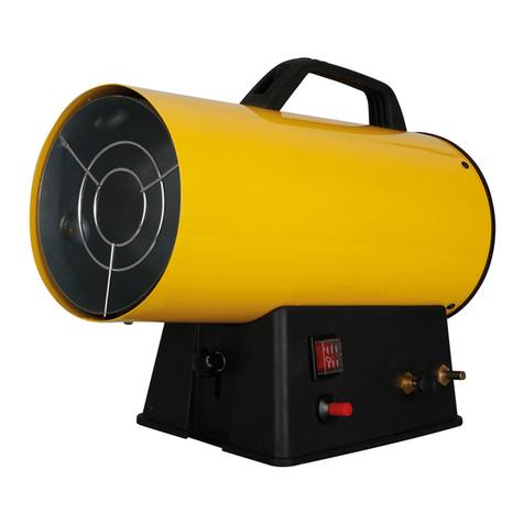
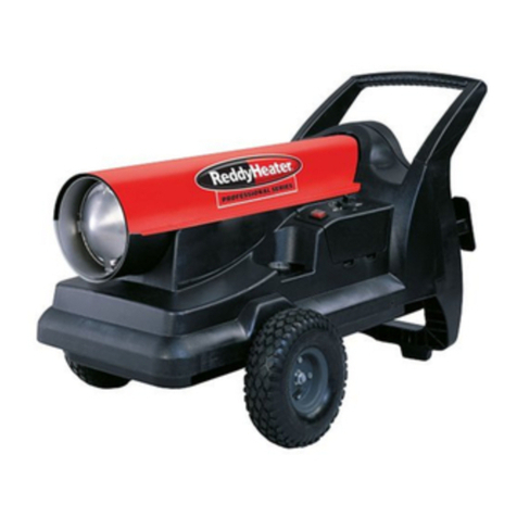
Desa R35D User manual

SERVICE MANUAL
LOW PRESSURE
PORTABLE FORCED AIR HEATER
HOT SURFACE IGNITION MODELS
SECTION A

2
Hot Surface Ignition Models Service Manual
SAFETY INFORMATION
WARNINGS
IMPORTANT: Read this owner’s manual carefully and
completely before trying to assemble, operate, or ser-
vice this heater. Improper use of this heater can cause
serious injury or death from burns, fire, explosion,
electrical shock, and carbon monoxide poisoning.
DANGER: Carbon monoxide poisoning may lead
to death!
Carbon Monoxide Poisoning: Early signs of carbon monoxide
poisoning resemble the flu, with headaches, dizziness, and/
or nausea. If you have these signs, the heater may not be
working properly. Get fresh air at once! Have heater ser-
viced. Some people are more affected by carbon monoxide
than others. These include pregnant women, persons with
heartorlungdiseaseoranemia,thoseundertheinfluenceof
alcohol, and those at high altitudes.
Makecertainyoureadandunderstandallwarnings.Keepthis
manual for reference. It is your guide to safe and proper
operation of this heater.
• Use only kerosene or No. 1 fuel oil to avoid risk of fire or
explosion. Never use gasoline, naphtha, paint thinners,
alcohol, or other highly flammable fuels.
• Fueling
a)Personnel involved with fueling shall be qualified and
thoroughlyfamiliarwiththemanufacturer’sinstructions
and applicable federal, state, and local regulations re-
garding the safe fueling of heating units.
b)Onlythetypeof fuelspecifiedon theheater’sdataplate
shall be used.
c)All flame, including the pilot light, if any, shall be extin-
guished and the heater allowed to cool, prior to fuel-
ing.
d)During fueling, all fuel lines and fuel-line connections
shallbe inspected forleaks.Any leaks shallberepaired
prior to returning the heater to service.
e)At no time shall more than one day’s supply of heater
fuel be stored inside a building in the vicinity of the
heater.Bulkfuelstorageshallbeoutsidethestructure.
f) All fuel storage shall be located a minimum of 25 feet
from heaters, torches, welding equipment, and similar
sources of ignition (exception: the fuel reservoir integral
with the heater unit).
g)Whenever possible, fuel storage shall be confined to
areas where floor penetrations do not permit fuel to
drip onto or be ignited by a fire at lower elevation.
h)Fuel storage shall be in accordance with the federal,
state, or local authority having jurisdiction.
• Never use heater where gasoline, paint thinner, or other
highly flammable vapors are present.
• Followall local ordinances and codeswhenusing heater.
• Heatersused in the vicinity of tarpaulins,canvas,or simi-
lar enclosure materials shall be located a safe distance
from such materials. The recommended minimum safe
distance is 10 feet. It is further recommended that these
enclosure materials be of a fire retardant nature. These
enclosure materials shall be securely fastened to pre-
vent them from igniting or from upsetting the heater due
to wind action.
• Use only in well-vented areas. Before using heater, pro-
vide at least a three-square-foot opening of fresh, outside
airforeach100,000Btu/Hrofrating.This heaterproduces
carbonmonoxide, which is listed bytheState of California
as a reproductive toxin under Proposition 65.
• Use only in places free of flammable vapors or high dust
content.
• Use only the electrical voltage and frequency specified
on model plate.
• Use only a three-prong, grounded extension cord.
• Minimum heater clearances from combustibles:
Outlet: 8 Ft. Sides: 4 Ft. Top: 4 Ft. Rear: 4 Ft.
• Locate heater on a stable and level surface if heater is
hot or running or a fire may occur.
• When moving or storing heater, keep heater in a level
position or fuel spillage may occur.
• Keep children and animals away from heater.
• Unplug heater when not in use.
• When used with thermostat, heater may start anytime.
• Never use heater in living or sleeping areas.
• Never block air inlet (rear) or air outlet (front) of heater.
• Never move, handle, refuel, or service a hot, operating,
or plugged-in heater.
• Never attach duct work to front or rear of heater.
• Approved by the New York City Fire Department under
certificate of approval #4803, #4860, #4908, or #4909.
To be used only at construction sites in accordance with
applicable New York City Codes, Regulations, Rules,
Directives, Permits, etc.
•Warning to New York City Residents For Use Only At
Construction Sites in accordance with applicable NYC
codesunderNYCFDcertificateof approval#4803, #4899,
#4908, #4909, or #4934.
For replacement parts contact:
www.PartsFor.com

3
Hot Surface Ignition Models Service Manual
TABLE OF CONTENTS
General Information
I. Arrangement of Manual.....................................3
III. Service Preparation...........................................3
IV. Tools Required ..................................................4
V. Parts..................................................................4
Specifications
I. General Specifications
1. Fuel Selection...............................................5
2. Electrical.......................................................5
3. Ventilation.....................................................5
4. Heater Sizing................................................5
II. Heater Performance Specifications...................6
Component Operation
I. Air System
1. Air Pump.......................................................7
2. Air Filters ......................................................7
3. Nozzle ..........................................................7
II. Electrical System
1. Motors ..........................................................7
2. Ignition Control/Photocell .............................8
3. Hot Surface Ignitor .......................................8
III. Fuel System ......................................................8
IV. Combustion System ..........................................9
V. All Systems Working Together .......................... 9
Troubleshooting
I. Safety Requirements.......................................10
II. Cautions ..........................................................10
III. Using The HA1170 Tester
1. Operation....................................................10
2. Calibration ..................................................10
IV. Diagnostic Charts............................................10
Wiring Diagrams.................................................23
GENERAL INFORMATION
I. ARRANGEMENT OF MANUAL
This manual contains information and service procedures to
assist the service technician in understanding and correcting
problems on DESA International oil-fired portable forced air
heaters. The first section of the manual contains basic infor-
mation concerning the operation of the different components
intheheater.This information should be reviewed by service
personnel to provide a basic understanding of how the com-
ponentsfunctionintheworkingsystem.The
Troubleshooting
sectionofthismanualisintendedtoprovideaquickreference
concerning conditions which result in customer complaints.
These procedures will help the service technician quickly
diagnose a malfunctioning heater. The illustrations in this
manual may not necessarily depict the actual heater model,
and are intended for reference ONLY.
III. SERVICE PREPARATION
A clean work area at the start of each job is essential for
efficient service work. Heaters which are extremely dirty
shouldbe cleaned prior to service. Cleaning will occasionally
uncovertheproblemarea.Toolsneededforthejobshouldbe
obtainedbeforeworkisstarted.Delaysresultingfromlocating
tools result in lost time and wages.
Cleanfuelshouldalwaysbeusedwhentestingheaters.Many
problems are often traced to the use of the wrong type of fuel
or dirty fuel.
Use caution and common sense when working on a heater.
Always remember that kerosene is flammable, and electrical
partscanresultinpotentialshock.Heaterpartsarehotduring
operation, which could result in burns.
For replacement parts contact:
www.PartsFor.com

4
Hot Surface Ignition Models Service Manual
V. PARTS
Inadditiontothestandardpartswenowofferpartskits.Listed
below are the item numbers and the accessory description
ITEM NUMBER ACCESSORY
HA1180 Air Gauge/All Models
HA1210 Thermostat/Forced Air & LP Forced Air
HA1202 Heavy Duty Wheel Kit
Fits: 35, 40, 50, 55, 60, 70 Models
HA1206 Wheel Kit
Fits: 35, 40, 50, 55, 60, 70 Models
HA2203 Rear Handle Fits: 110, 115 Models
HA2204 Rear Handle
Fits: 150, 155, 165, 200 Models
HA2210 Filler Neck Screen
ITEM NUMBER REPLACEMENT PART
104068-03 Ignition control
Fits: 35, 40, 50, 55, 60 Models
104068-02 Ignition control Fits: 70, 110, 115,
150, 155, 165, 200 Models
PP204 Rotor Kit 1/2"
PP206 Nozzle (35, 40 Models)
Refer to Owner’s Manual Nozzle (50/55 Models)
PP219 Nozzle (60 Models)
PP220 Nozzle (70 Models)
PP221 Nozzle (110, 115 Models)
PP222 Nozzle (150, 155 Models)
PP223 Nozzle (165 Models)
PP235 Nozzle (200 Models)
PP200 Hot Surface Ignitor
PP213 Air Filter Kit
(35, 40, 50, 55, 60, 70 Models)
PP214 Filter Kit
(110, 115, 150, 155, 165, 200 Models)
PP205 Rotor Kit 5/8"
M16656-24 Photocell
PP217 Pump Adjustment Kit
IV. TOOLS REQUIRED
In addition to common hand tools, the service shop should
have the following tools and instruments for proper repairing
of the heaters. These instruments will be referred to through-
out this manual.
INSTRUMENT RANGE PART NUMBER
Control/Photocell Tester N/A HA1170
Pressure Gauge 0-15 P. S. I. HA1180
Feeler Gauge .001 to .1 inch None*
Multimeter 0-250 VAC None**
0-200 Ohm
*Available at any auto parts store.
**Available at most electronic stores.
.025
.0015
HA1170
Control
Tester
Pressure Gauge
Feeler
Gauge
Multimeter
For replacement parts contact:
www.PartsFor.com

5
Hot Surface Ignition Models Service Manual
SPECIFICATIONS
I. GENERAL SPECIFICATIONS
1. Fuel Selection
One of the most critical specifications for trouble-free opera-
tion is the use of a clean, acceptable fuel. Listed below are
guidelines and comments concerning operation of heaters
with different fuels.
RECOMMENDED COMMENTS
FUELS
Kerosene
Fuel Oil No.1
Jet "A"
ALTERNATE FUELS COMMENTS
Fuel Oil No. 2
Diesel No. 1
Diesel No. 2
2. Electrical
The heater must be connected to a standard electrical outlet
(120V/60HZ).Forsafety,allheatersareequippedwithathree
prong power cord, which must be grounded. When selecting
anextensioncordforheaterusage,thefollowingchartshould
be used in determining wire size.
LENGTH OF CORD WIRE SIZE (AWG)
100 Ft. No. 14
200 Ft. No. 12
300 Ft. No. 10
400 Ft. No. 8
No. 6
Bestoverallresults.Minimumodorand
minimum maintenance. No additives
necessary for cold weather operation.
Noticeableincreaseinodor.Requires
frequent maintenance of fuel filter
and nozzle. Requires a winterizing
additive at temperatures below 20°F
3. Ventilation
Theheater should be usedonlyin well-ventilated areas.Asa
rule,thefollowingminimumrequirementsshouldbefollowed.
HEATER SIZE (BTU) SQUARE FOOT OPENING
35,000/40,000 1.0 Sq. Ft.
50,000/55,000/60,000 1.6 Sq. Ft.
70,000 2.1 Sq. Ft.
110,000/115,000 3.2 Sq. Ft.
150,000/155,000 4.5 Sq. Ft.
165,000 5.0 Sq. Ft.
200,000 6.0 Sq. Ft.
The above is based on ventilation requirements of at least a
3 sq. ft. opening per 100,000 BTU. If possible, it is better to
provide cross-ventilation to achieve better air movement.
4. Heater Sizing
The user should be aware of the proper size heater needed
foraparticularapplication.Itiseasytoseethata35,000BTU
heater would not heat a large warehouse, but the question is
sometimes asked "What size heater should I use?" A simple
formula that can be used to determine heater BTU require-
ments follows:
Cu. Ft. of Area X .133 X Desired Temp. Rise °F = BTU Size
Needed.
Example:
Area: 50' X 25' X 10' = 12,500 Cu. Ft.
Desired Temp. Rise: 30°F
12,500 (Cu. Ft.)
X .133 (Factor)
1662.5
X 30 (Temp. Rise)
49,875 (Proper Heater Size)
ANSWER:
A 50,000 BTU
heater should be selected
for this application.
For replacement parts contact:
www.PartsFor.com

6
Hot Surface Ignition Models Service Manual
Heater Model BTU Pump Nozzle Nozzle Motor Motor Motor Ignitor Control Fuel Hot Air AMPS
Rating PSI Part No. GPH Part No. R.P.M. Horsepower Kit Board Tank Output (Running)
±.1 ±5% Capacity (C.F.M.)
(Gal)
R35D 35,000 3.0 100735-02 0.30 100088-01 1725 1/15 102548-03 104068-03 3.0 165 2.0
REM35C (HA3006) (102001-01)
R40 40,000 3.0 100735-02 0.30 100088-01 1725 1/15 102548-03 104068-03 3.0 170 2.0
REM40 (HA3006) (102001-01)
R55A 55,000 3.6 100735-17 0.40 100088-01 1725 1/15 102548-03 104068-03 5.0 175 2.0
REM55A (HA3024) (102001-01)
R60 60,000 3.4 100735-17 0.40 100088-01 1725 1/15 102548-03 104068-03 5.0 180 2.0
REM60 (HA3024) (102001-01)
RM60
R70D 70,000 4.7 100735-18 0.50 103609-01 3450 1/8 102548-03 104068-02 5.0 250 2.8
R70DT (HA3026) (102001-20)
R110B 110,000 5.3 100735-19 0.80 103493-01 3450 1/5 102548-03 104068-02 9.0 490 3.6
R110BT (HA3027) (102001-21)
R115 115,000 5.3 100735-19 0.80 103493-01 3450 1/5 102548-03 104068-02 9.0 490 3.6
REM115 (HA3027) (102001-21)
RM115
REM150E 150,000 5.4 100735-20 1.10 103493-01 3450 1/5 102548-03 104068-02 13.5 550 3.6
(HA3028) (102001-21)
R155B 155,000 5.4 100735-20 1.10 103493-01 3450 1/5 102548-03 104068-02 13.5 550 3.6
REM155B (HA3028) (102001-21)
RM155
R165AT 165,000 5.6 100735-21 1.20 103493-01 3450 1/5 102548-03 104068-02 13.5 575 3.6
(HA3029) (102001-21)
R200A 200,000 6.2 100735-31 1.40 105183-01 3400 1/4 102548-03 104068-02 13.5 600 3.6
(102001-27)
M16656-24 Photocell will apply to all models for service.
II. HEATER PERFORMANCE SPECIFICATIONS
Technical Service Heater Performance Data
For replacement parts contact:
www.PartsFor.com

7
Hot Surface Ignition Models Service Manual
COMPONENT OPERATION
I. AIR SYSTEM
1. Air Pump
The heater's air pump consists of a rotor with four carbon
bladesrotatinginsideapumpbody.Therotorisdrivendirectly
by the motor and is attached to the motor shaft by means of
aplasticinsert.Asthemotorrotates,thecarbonblades travel
outward rubbing against the inside surface of the steel pump
body. The rotor's position inside the pump body is such that
it is not concentric with the pump body and a .003/.004 of an
inch gap is set at the uppermost quadrant. As the motor
rotates,theairbetweenthebladesiscompressedandrouted
to the nozzle through the air line.
2. Air Filters
Theair filtering systemconsistsof an airinputfilter and anair
outputfilter.Theairinputfilterislocatedattherightrearofthe
motor and its purpose is to filter all incoming air prior to
entering the air pump. The filter design is such that it can be
cleaned in a mild, soapy solution, thoroughly dried and used
overagain.Theairoutputfilterislocatedundertheplasticend
cover.Thisfilter'spurposeistopreventanycarbondust(from
rotor or blade wear) from entering the air passages in the
nozzle. This filter is non-cleanable and should be replaced
when considerable buildup of carbon dust is observed. (See
drawings below).
Gap Adjusting
Screw
Blade
Pump Body
Air Intake Side
Air Output
Side
.003/.004
Clearance
Measured
with Feeler
Gage
Rotor
Motor Shaft
Insert
Direction of Rotation-Clockwise
35,000, 50,000, 55,000, and
70,000 BTU
Filter System
110,000, 115,000, 150,000,
155,000, 165,000, and 200,000
BTU Filter System
Air Output Filter
Air Input
Filter
Air Output Filter
Air Input
Filter
3. Nozzle
As mentioned previously, the purpose of the air pump is to
compressairanddeliverittothenozzle.Thecompressedair,
as it travels through the nozzle, creates a negative pressure
that extends back through the center of the nozzle. This
negativepressureliftsthefuelfromthefueltank.Thefuelfrom
the fuel tank and the compressed air are mixed at the nozzle
which results in a very fine mist of fuel being sprayed into the
combustionchamber.Theairpump/nozzlecombinationelimi-
nates the need for a conventional type fuel pump. It is
important for the service technician to understand the nozzle
operation.Inmany casesconcerningimproperoperationof a
heater, the problem is the result of a seal leak or a restriction
(dust/dirt) being present within the nozzle. It should also be
pointedout thateachmodel heaterrequires different nozzles
due to different fuel flow rates.
Nozzle Face
Compressed
Air From
Pump
Fuel Lifted From Tank
by Negative Pressure
II. ELECTRICAL SYSTEM
1. Motors
The motors used on the low pressure heaters are fractional
horsepower motors ranging from 1/15 HP on the smallest
heaterto1/4HPonthelargestheaters.Themotorsusedcan
be grouped into two categories. The first category is the
shaded pole motor. The shaded pole motor contains a single
windinganddoesnotrequireanintegralstart/runcapacitorfor
operation.Thistypeofmotorisusedon35,40,50,55,and60
model heaters.
The second category is the permanent start capacitor motor.
This motor contains two separate windings. The first winding
being the auxiliary or start winding and the second being the
main or run winding. This motor utilizes an integral start/run
capacitor which is wired internally and cannot be replaced.
Thistype ofmotoris usedon the 70,110, 115,150,155, 165,
and 200,000 Btu models.
MOTOR
AC LINE
AC LINE
CAPACITOR
AUX
MAIN
Shaded Pole Motor Permanent Start Capacitor Motor
For replacement parts contact:
www.PartsFor.com

8
Hot Surface Ignition Models Service Manual
3. Hot Surface Ignitor
All models will use 102548-03 Ignitor Kit.
The hot surface ignitor is rated for 120 volts. With the rated
voltageapplied,theignitorelementheatsupto1400ºCelsius
(2550ºFahrenheit)within5seconds.Whentheatomizedfuel
is sprayed by the nozzle it is ignited by this extremely hot
surface.
Note:
It is important for the service technician to be cautious
whenworking with the hot surfaceignitordue to its extremely
highoperating temperature. Careshould also betakennot to
bend or strike the ignitor element.
III. FUEL SYSTEM (FUEL FILTERS)
There are several types of fuel filters used on different model
heaters. The filters are always located in line with the fuel
pickup tube. The purpose of the filter is to eliminate the
possibility of dirt, dust, etc. from entering the nozzle and
restricting the flow. The filters should be inspected and
cleaned whenever a heater is brought in for service. It is also
important that the bottom of the tank be inspected for sedi-
mentation or dirt buildup. The filter’s design is such that a
possible restriction in the filter screen can be present during
operationandbedislodgedbackintothetankwhentheheater
is shut off.
2. Ignition Control/Photo Cell
The ignition control circuit consists of a photocell (light sensi-
tive resistor) and an ignition control. The photocell is used to
sense the presence of light inside the combustion chamber.
The resistance of the photocell changes as the light level
insidethe combustion chamber changes. When the heater is
operating properly, the flame pattern inside the combustion
chamberisveryturbulentwhichresultsintheresistanceofthe
photocell increasing and decreasing very rapidly. This dy-
namic change in resistance is required by the ignition control
toallowtheheatertocontinuetooperate.Ifthesignalfromthe
photocell becomes “lazy” or steady state indicating a lack of
turbulence,thentheheaterwillbeturnedoff.Someexamples
ofthisconditionarealossoffanandablockedinlet.Because
the photocell also responds to the color of the flame, the
control will also shut off the heater if the fuel/air mixture is too
lean.Withafuelleanmixturetheflamebecomesblueincolor
and the photocell does not respond to that end of the light
spectrum as well as it responds to orange light which is
present during proper operation. As a service technician, it is
important to understand the operation of the ignition control.
In the past, it has been the single most misdiagnosed part of
the heater. It is suggested that all controls be checked per
instructions listed in the
Troubleshooting
section, prior to
replacement.
Photocell
Ignition Control
(mounted on side cover)
Ignitor Element
Ignitor
Block
35, 40, 50, 55,
60, and 70,000
Btu Models
110, 115, 150,
155, and 165,000
Btu Models
200,000 Btu
Model
For replacement parts contact:
www.PartsFor.com

9
Hot Surface Ignition Models Service Manual
IV. COMBUSTION SYSTEM
Airbeing blownby thefan isdirectedby theair deflectorsinto
the combustion chamber through the two louvers and center
opening in the rear head which is riveted to the back of the
combustion chamber. The nozzle and nozzle adapter are
mounted in the burner strap which is fastened to the rear
head. As the atomized fuel exits the nozzle and is ignited it
mixes with the air entering through the rear head. The
combustion process is completed inside the combustion
chamber and the hot air exits the outlet end of the chamber.
V. ALL SYSTEMS WORKING TOGETHER
There are four basic systems within the heater: the fuel
system, the air system, the electrical system, and the com-
bustion system.
An air pump (A) on one end of the motor shaft forces air
through the air line (G) and out the nozzle (I). The moving air
creates a pressure differential in the nozzle adapter (N)
causingfueltobedrawnfromthetank(J).Thefuel-airmixture
is sprayed into the combustion chamber (L) in a fine mist.
Additionalairissuppliedtothecombustionchamberbyafan
(O) to enter the combustion chamber where it mixes with the
air and fuel from the nozzle. The remaining air is directed
aroundandoverthecombustionchamber.Thisairmixeswith
theheatedairfromthecombustionchamberandisejectedas
a jet of clean, heated air (K).
The ignition system consists of an ignition control assembly
(E) and hot surface ignitor (M). The ignition control assembly
applies120voltpowertothehotsurfaceignitorfor10seconds
which consists of a 5 second preheat period and a 3 to 4
second ignition trial period. The extremely high temperature
oftheignitorelementignitesthefuelandairmixturewithinthe
combustion chamber. After the trial period the power is
removed from the ignitor.
In the safety circuit, the photocell monitors the amount of
flame turbulence inside the combustion chamber.
A
O
N
Air For Fuel System Air For Combustion Fuel
E
G
LM
I
J
K
Fan
Air Deflector
For replacement parts contact:
www.PartsFor.com

10
Hot Surface Ignition Models Service Manual
IV. DIAGNOSTIC CHARTS
Thefollowingpagescontainvariousdiagnosticcharts.Touse
thecharts,findthe"ObservedFault"thatexistsandfollowtest
procedure.
Observed Fault Index
Motor starts and runs but fuel does not ignite ................. 11
Ignitor element heats up but motor does not start within
five seconds................................................................... 14
Ignitor does not heat up and motor does not start within five
seconds........................................................................... 17
Ignitor heats up, motor starts and runs, and fuel ignites, but
heater shuts off after a short period of time .................... 18
Delayed Ignition .............................................................. 22
Battery
TROUBLESHOOTING
I. SAFETY REQUIREMENTS
Thisservice manualis intendedforuse byindividuals withan
adequate knowledge of electrical and mechanical skills. At-
tempts to repair this heater by individuals without those skills
can result in personal injury, as well as property damage.
II. CAUTIONS
1. Before servicing, disconnect the heater from the electri-
cal power source by removing the electrical plug from
the wall receptacle.
Note:
When certain tests require electrical power to be
applied, connect electrical power only for the time nec-
essary to complete the test.
2. Do not bypass safety devices except when instructed to
do so during troubleshooting procedures.
3. Ifreplacement parts are necessary, donotsubstitute with
non-factory parts (use only factory authorized replace-
ment parts).
4. Make sure all electrical connections are secure and cor-
rect prior to connecting heater to a grounded electrical
power source.
III. USING THE HA1170 TESTER
The HA1170 control/photocell tester provides a means of
troubleshooting the forced air kerosene heater by verifying
the operation of the ignition control and photocell.
Operation
The tester’s toggle switch has three positions. The middle
position puts the tester in the OFF mode. The switch should
be kept here when the tester is not in use to conserve battery
power. With the switch in the ON position, the red LED is on
continuous.This2foot-candlelightsourcecanbeusedtotest
the static resistance of the photocell. With the switch in the
PULSEposition,theredLEDflashesoffandonatarateof10
timespersecond(10hertz).Thisposition isusedto verifythe
proper operation of the ignition control.
Calibration
IMPORTANT:
This tester will not function properly without
adequatebattery power.Prior tousingthe tester,the fullload
battery voltage must be verified as follows.
Remove the battery cover to expose the battery and termi-
nals. With the battery connected and the switch in the ON
position (LED on continuous), measure the D.C. voltage
across the battery terminals. If this voltage reads 7.5 volts or
higher, proceed with testing. If the voltage reads lower than
7.5volts,replacethebatteryandconfirmthefullloadvoltage.
HA1170 Tester
Battery
Terminals
Battery Cover
Toggle Switch
LED Light
Test Leads
For replacement parts contact:
www.PartsFor.com

11
Hot Surface Ignition Models Service Manual
OBSERVED FAULT
Motor Starts and Runs but Fuel Does Not Ignite
Does Ignitor Element Heat Up?
No Yes
Check for
Defective Ignitor
WARNING: HighVoltage!
Defective Ignition
Control Assembly
Check for Proper Pump Pressure
Check for Restricted Fuel Flow
Due to:
A. Seal leak
B. Restriction in Nozzle or Nozzle Adapter
C. Defective Solenoid Valve
(200,000 Btu Models Only)
Fuel Filter Restriction
1
2
3
5
4
TEST PROCEDURE
1 Check Ignitor
Disconnect ignitor wires from ignition control assembly.
Measurethe resistance of theignitorat the terminalswith
an ohmmeter (use 0-200 OHM scale). Ignitor resistance
shouldmeasure 30to175 OHMS.If resistance measures
outside of this range, then ignitor is defective and should
be replaced.
2 Check Ignition Control Assembly
Remove fuse cover and check fuse (70,000 to 200,000
Btu models only). If fuse is blown replace it with a GMA-
10 fuse. Disconnect motor red and white wires from con-
trol. With Ignitor wires disconnected, attach voltmeter
leadsto the ignitor terminals (labeled IGNITOR).Use the
0 to 200 V.A.C. scale. Plug power cord into a grounded
120V/60 Hz outlet. Meter should read 120V(rms) for ap-
proximately 10 seconds. If voltage reads 0 or stays at
120 for more than 10 seconds, the control is defective
and should be replaced.
WARNING: High Voltage!
Ignition Control
For replacement parts contact:
www.PartsFor.com

12
Hot Surface Ignition Models Service Manual
3 Check for Proper Pump Pressure
Install HA1180 Pressure Gauge or equivalent to rear of
air filter housing. Start heater and adjust air pressure to
specifiedpressure.Turn adjustmentscrew clockwise
to increase pressure and counterclockwise to de-
creasepumppressure.Thescrewdrivermust beremoved
from the slot after any adjustment before taking a read-
ing on the gauge. (See
Heater Performance Specifica-
tion
on page 6 for specified pressures).
Note:
Pressure gauge must be scaled in 1/4 pound in-
crements for accurate measurement.
Nozzle Face
Nozzle
Nozzle
Seal
Nozzle
Adapter
Bracket Air Line
Fitting
Nozzle
Adapter
4 Check for Restricted Fuel Flow
35,000 to 165,000 Btu Models Remove air and fuel lines
fromnozzle adapter.Remove nozzle adapter/nozzlefrom
bracket.
200,000 Btu Model Remove ignitor(do not strike or bend
element) from bracket. Place in a safe location. Remove
air and fuel lines from nozzle adapter. Remove two
bracketscrews and remove bracket, nozzle adapter, and
nozzle assembly from combustion chamber.
Using a 5/8" socket wrench, carefully remove the nozzle
fromnozzleadapter.(Beextremelycarefulnotto scratch
or score the face of the nozzle).
A. Seal Leak
Inspect nozzle seal or o-ring for damage. Replace if nec-
essary.
Combustion
Chamber Nozzle/
Adapter
Assembly
35,000 - 165,000 Btu Models
Nozzle Face
Nozzle
Nozzle
Seal
Nozzle
Adapter
Air Line
Fitting Fuel Line
Fitting
200,000 Btu Models
Fuel Line Fitting
For replacement parts contact:
www.PartsFor.com

13
Hot Surface Ignition Models Service Manual
Note:
Fuel Filter Location
May Vary According To
Model. Refer to
Fuel
System,
page 8.
Fuel Filter,
Bushing,
and Lower
Fuel Line
B. Restriction in Nozzle or Nozzle Adapter
Using a compressed air source, blow the compressed
air through the outlet end of nozzle to dislodge any for-
eign debris.
CAUTION:NEVERDRILLOUTORTRYTOINCREASE
NOZZLE SIZE.
Also, blow compressed air through the nozzle adapter in
the direction shown to dislodge any foreign debris.
Blowing Compressed Air Through Nozzle
C. Defective Solenoid Valve (200,000 Btu model only)
Remove upper and lower fuel lines from fittings on sole-
noidvalve.Apply120V/60Hzpowertovalve.Shineaflash-
light at one side of valve. Light should be visible from the
otherside whenthesolenoid isenergized.If not, thevalve
is obstructed or defective. Clean or replace as necessary.
100,000 - 165,000 Btu Models Shown
Fuel
Flow
Direction
Flush
In This
Direction
5 Fuel Filter Restriction
The fuel filter should be inspected and cleaned (see sec-
tion III,
Fuel System (Fuel Filters),
page 8. After remov-
ing filter, flush with clean kerosene in the reverse direc-
tion of the fuel flow.
Blowing Compressed Air Through Nozzle Adapter
35,000 - 165,000 Btu Models
200,000 Btu Models
For replacement parts contact:
www.PartsFor.com

14
Hot Surface Ignition Models Service Manual
Ignitor Element Heats Up But Motor
Does Not Start Within Five Seconds
Rotate Fan by Hand to Determine
if Fan Rotates Easily
Fan is Difficult to Rotate Fan Rotates Easily by Hand
Broken Rotor or Blades
Improper Rotor Clearance
Oversized Rotor
Dry Motor Bearing
Open Motor Winding
Defective Ignition Control Assembly
Defective Start/Run Capacitor
Improper Voltage to Heater
1
2
3
4
5
6
7
8
TEST PROCEDURE
1 Broken Rotor or Blades
Disassemble the end cover filter and end pump cover
from rear of motor. Visually inspect the rotor and blades
for breakage. Make sure that the rotor and blades are
free of any type of lubricant. Rotor and blades must be
clean and dry for proper operation.
2 Improper Rotor Clearance
Check rotor with feeler gauge for proper clearance
(.003"-.004") between rotor and pump body. Rotate ro-
tor and make sure all four quadrants of rotor have ad-
equate clearance.
3 Oversized Rotor
If the fan is hard to turn when the motor end cover is
installed,but easytoturn whenloosened, the rotorshould
be removed and lightly sanded. Remove the rotor and
lightlysand by placingrotor in thepalmof hand andsand-
ing on a flat surface making figure eight rotations. (Use
the finest grade of sandpaper available).
OBSERVED FAULT
Blade
Rotor
Pump Body
Gap
Sandpaper
For replacement parts contact:
www.PartsFor.com

15
Hot Surface Ignition Models Service Manual
Note:
Motor may vary
according to model
4 Dry Motor Bearing
If the fan is difficult to turn with air pump parts removed,
then motor bearings are defective. Bearings are perma-
nently lubricated, therefore motor should be replaced.
5 Open Motor Windings
Disconnectmotor wires (red andwhite)from ignition con-
trol assembly. Attach the ohmmeter leads to the moter
wire terminals. Using the 0 to 200 OHM scale, measure
the resistance of the motor windings. Refer to the chart
below for resistances for each model. If the resistance is
not within the specified range motor is defective and
should be replaced.
NOTE:
Resistancesmayvaryduetomotortemperature.
MOTOR WINDING RESISTANCE
MODEL RESISTANCE
RANGE (OHMS)
35,000, 50,000, 55,000, 60,000 5.57-6.81
70,000 6.03-7.37
100,000, 110,000, 150,000
155,000, 165,000 4.14-5.06
200,000 3.96-4.84
Note:
In some cases it is possible for the resistance to read
correctly without power applied and the motor still not work
with power applied. If the ignition control assembly is tested
and found to be good, then the motor is defective and should
be replaced.
For replacement parts contact:
www.PartsFor.com

16
Hot Surface Ignition Models Service Manual
6 Defective Ignition Control Assembly
Disconnect motor wires from control. Attach voltmeter
leads to motor terminals on control. Use 0 to 200 V.A.C.
scale on meter. Plug power cord into a 120V/60 Hz
grounded outlet. Meter should read 0 volts for five sec-
onds, 120 volts for 3 to 4 seconds, then drop to 0 volts. If
the meter remains at 0 volts, the control is defective and
should be replaced.
7 Defective Start/Run Capacitors
Motors used in 70,000 to 200,000 Btu model heaters are
the Permanent Start Capacitor (PSC) type and are
equipped with an integral start/run capacitor. If the resis-
tance of the motor windings read correctly and the igni-
tion control assembly is found to be working properly,
thecapacitor maybe "open"circuit.Thecapacitor iswired
internally and cannot be replaced. No service parts are
availableandentire motor assembly should be replaced.
8 Improper Voltage Input to Heater
The specified voltage operating range for this product is
108 to 132 volts (rms) 60 hertz. Verify that the voltage
appliedtothe heater while the motor is running is at least
108 volts and does not exceed 132 volts. Refer to the
Electrical
section of this manual (page 5) for proper ex-
tension cord sizing.
For replacement parts contact:
www.PartsFor.com

17
Hot Surface Ignition Models Service Manual
Ignitor Does Not Heat Up and Motor
Does Not Start Within 5 Seconds
Possible Causes External to Heater Possible Causes Internal to Heater
Circuit Breaker is Tripped
Check for Broken or Frayed Wires
on Power Cord or Extension Cord
If External Thermostat is Used,
Plug Heater Directly Into AC Source
to Isolate Source of Problem
Bad Electrical Connection(s) or
Wired Incorrectly
Blown Fuse on Ignition Control
Assembly
Defective Ignition Control Assembly
1
2
3
TEST PROCEDURE
1 Bad Electrical Connection(s) or Wired Incorrectly
Verify that all connections to the ignition control assem-
bly are secure and wired according to the wiring diagram
on page 23.
OBSERVED FAULT
Checking Fuse
Fuse
Ignitor
Fuse
Clips
2 Blown Fuse on Ignition Control Assembly
Remove fuse cover and inspect fuse. Check for continu-
ity with an ohmmeter. If fuse is open, replace with a fuse
of the same type and rating (GMA-10).
3 Defective Ignition Control Assembly
With motor and ignitor wires disconnected, connect volt-
meter leads to the ignitor terminals. Use the 0 to 200
V.A.C. scale on the voltmeter.Apply power (120V/60Hz)
to the control. The meter should read 120 volts for ten
seconds and then drop to 0 volts. Remove power to con-
trol. Connect meter leads to the motor terminals. Apply
power to control. Meter should read 0 volts for five sec-
onds, 120 volts for 3 to 4 seconds, then drop to 0 volts. If
measurementsdifferfromthosedescribed,control is de-
fective and should be replaced.
Motor
Ignitor
Motor
Meter Leads
For replacement parts contact:
www.PartsFor.com

18
Hot Surface Ignition Models Service Manual
Ignitor Heats Up, Motor Starts and Runs, and Fuel Ignites,
But Heater Shuts OffAfter a Short Period of Time
Ignition Control Trips out Within the
First Ten Seconds of Operation Safety Control Trips out After
Ten Seconds of Operation
Photocell Boot Not Properly Seated
in Bracket
Check for proper Pump Pressure
Dirty/Clogged Filters in Compressor
Check for Restricted Fuel Flow
Due to:
A. Seal Leak
B. Filter Blocked
C. Restriction in Nozzle or
Nozzle Adapter
Fuel Cap and Gasket Not Vented
4
5
6
7
8
Defective Ignition Control
Bad Electrical Connection(s) or
Wired Incorrectly
1
2
3
Defective or Dirty Photocell
TEST PROCEDURE
1 Defective Ignition control
Remove pressure gauge plug from filter end cover. Re-
move 4 side cover screws that attach the side cover to
theheater.Allowsidecover(with ignitioncontrol attached)
to rest on fuel tank flange. Disconnect only the photocell
wires from ignition control. Attach the HA1170 leads to
the photocell terminals on the ignition control. Plug the
power cord into a grounded 120V/60 Hz outlet. When
the motor starts turn the HA1170 toggle switch to the
"flashing" red LED position (see page 10 for HA1170
calibration procedures). If the motor shuts off after 3 or 4
seconds,the control is defective and shouldbereplaced.
If the motor continues to run in step 1, the photocell may
be dirty or defective.
OBSERVED FAULT
Toggle Switch
Flashing
Red LED Test Leads
Photocell
Ends
For replacement parts contact:
www.PartsFor.com

19
Hot Surface Ignition Models Service Manual
2 Defective or Dirty Photocell Assembly
Inspectthe lens of the photocell for soot/dirt, etc...Ifdirty,
wipe off with a clean, damp cloth.
Removephotocell assembly from heater.Turnthe toggle
switch on the HA1170 tester to the "solid" red LED posi-
tion. Place the photocell boot over the red LED on the
tester. Connect the leads of an ohmmeter to the termi-
nalson the photocellassembly.Use the 0 to20,000 OHM
scale on the meter. The resistance should measure
11,000 OHMS or less. If not the photocell is defective
and should be replaced.
Block off the light source by putting thumb over opening
of photocell. Replace the photocell if a change in resis-
tance is not observed.
The resistance should measure greater than 50,000
OHMS (use the 1 megohm scale on the meter).
3 Bad Electrical Connection(s) or Wired Incorrectly
Verify thatall electrical connectionsare secure and mak-
ing electrical contact. Verify that wiring is per the wiring
diagram (see diagram, page 23).
4 Photocell Boot Not Properly Seated in Bracket
Make sure photocell boot is seated in bracket securely.
See illustration that follows.
Photocell
Photocell
Correct Photocell Placement
Incorrect Photocell Placement
For replacement parts contact:
www.PartsFor.com

20
Hot Surface Ignition Models Service Manual
5 Check for Proper Pump Pressure
Install HA1180 Pressure Gauge or equivalent to rear of
air filter housing. Start heater and adjust air pressure to
specified pressure. Turning adjustment screw clockwise
increases pressure, counterclockwise decreases pres-
sure. The screwdriver must be removed from the slot
after any adjustment before taking a reading on the
gauge. (See
Heater Performance Specification,
on page
6 for specified pressures). It may be necessary to con-
nect the HA1170 tester in place of the photocell while
adjustingthe pressure dueto the fastshutdownresponse
of the control.
Note:
Pressure gauge must be scaled in 1/4 pound in-
crements for accurate measurement.
6 Dirty/Clogged Air Filters in Compressor
Inspect and replace air intake, air output, and lint filter if
necessary. Filters should be replaced after 500 hours of
operation.
HA1180
Pressure
Gauge
Flat Blade
Screwdriver Adjustment
Screw
Fan Guard
Filter End
Cover
Air
Intake
Filter
Pump
Plate
Blade
Air Output Filter
Rotor
Insert
For replacement parts contact:
www.PartsFor.com
This manual suits for next models
21
Table of contents
Other Desa Heater manuals
Popular Heater manuals by other brands

Brant Radiant Heaters
Brant Radiant Heaters HL3 Series user manual

Harvia
Harvia M45 Instructions for installation and use

EUROM
EUROM Mon Soleil DSP Wifi Series instruction manual

Rointe
Rointe Napoli aqua instruction & installation guide

Robur
Robur AY00-119 Series manual

EINHELL
EINHELL SH 2000 operating instructions

point
point POHF4020 user manual

Dimplex
Dimplex VFMQ 30 Installation and operating instructions

Truma
Truma Trumatic E 2400 E Operating and installation instructions

Stanley
Stanley ST-40-GFA-E manual

EUROM
EUROM The Box 2400 instruction manual

L.B. White
L.B. White Workman CV225 Owner's manual and instructions