DESi Utopic 2 User manual

Wireless Motorized Cylinder
With Remote Controller
USER
MANUAL
URC 60

1. GENERAL INFORMATIONS and WARNINGS
- We recommend you to put the keys to an accessible place (like car, bag etc.) in an
emergancy condition.
- If there is any problem with door or locking mechanism, first of all, those problems need to
be solved. Door's mechanical parts and locking mechanism should be working properly.
- If there is a problem with the device, first look to the troubleshooting part of this manual. If
you cannot solve the problem, contact with your dealer.
- Replace the batteries, if there is a battery warning. RECYCLE EMPTY BATTERIES!
- All the system need to be protected from water, direct sunlight and shocks.
- Place the batteries after installation of the system to the door. If the batteries are placed
before the installation, auto-rotating parts may cause injuries. WATCH YOUR FINGERS!
!
We would like to thank you for choosing this patented product. We hope you to enjoy it.
DES Alarm and Securty System Inc.

3
1.1. FEATURES OF THE DEVICE
Structure
Engraved block alluminum
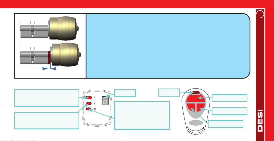
Cylinder Length
(outside) 26 mm | 10 mm | 34 mm (inside)
Inside part can extensile up to 40 mm with extending parts.
(Different cylinder lengths are available)
Batteries and Battery Life
5x 1,5 V AA size Alkaline or Lithium batteries.
Device is suitable to use with rechargable batteries.
According to tests done in DESi labratories, battery life of the
device is measured as follows:
3 years standby or
10.000 operations (locking or unlocking) for 3 rotation locks
Remote Controller
434 Mhz Anti-duplicatiion rolling code remote controller with
action display
Remote Controller (wireless device) Memorry
Motorized cylinder can learn up to 40 remote controllers.
Controlling Options and Compatible Accessories
Wireless Fingerprint Reader
Wireless Keypad
Bluetooth Interface
Wireless Auto-Locking Module
Wireless Home Automation Interface
Wireless Secretary Button
Remote Access Module
1.2. BOX CONTENT (may vary according to model number)
1x Wireless Motorized Cylinder (with keys)
1x Master Remote Controller
2x User Remote Controller
1x Installation screw and Hex key
User Manual

42. PARTS OF REMOTE CONTROLLED MOTORIZED CYLINDER and INSTALLATION
Cylinder
Handle
Handle Screw
Hex Screw
The hole
for hex key
DEMOUNTING OF MOTOR AND CYLINDER
- Open “handle screw” and remove the handle by pulling.
- Remove the batteries.
- Rotate “hex screw” to counter-clock wise by using the
hex key out of the box. You will see the cylinder will be
disassembled from the motorized part.
To assemble two parts, combine cylinder and motorized
part in a proper way and rotate hex screw to clock wise.
Metal Extending Parts
(used if needed)
Plastic Cover Cover Spring
5
Master RC
Full-Turn Locking
In the administrator menu;
Shift to next menu item or Confirm
Unlock and Open
In the administrator menu;
Shift to previous menu item
1 Turn Locking
To enter administrator menu,
press 3 seconds.
In the administrator menu;
Enter to displayed menu item.
Display
2
1
3
Full-Turn Locking
1 Turn Locking
Unlock and Open
Display
User RC
Up to 6 mm
EXTENDING INSIDE PART OF THE CYLINDER (if needed)
If the door thickness is not suitable to the cylinder of the device, inside part of the
cylinder may be extended up to 6 mm by 2 mm steps.
To extend the cylinder’s inside part, follow the instructions below:
- Open “handle screw” and remove the handle by pulling.
- Remove the batteries.
- Rotate “hex screw” to counter-clock wise by using the hex key out of the box till the
motorized part is disassembled from the cylinder.
- Add 2 mm metal extending parts as needed.
- Assemble cylinder and motorized part and rotate hex screw to clock wise direction.
- Install the batteries and check the device if it is working properly or not.
26 10 34
26 10 40
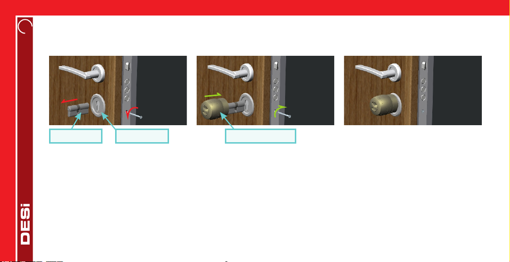
62.1. INSTALLATION OF MOTORIZED CYLINDER
2.1.1. Installing The Device Without Plastic Cover (Recommended for ordinary people)
This is the easiest installation. It is suitable for all kind of doors.
In some security doors, even if you remove cylinder screw, you cannot remove cylinder due to cramped installation of cylinder
defender. Follow the instructions below, for that kind of situations: (Recommended for professional installers.)
- Untighten screws of cylinder defender (don’t remove the screws)
- Remove cylinder screw and take out the old cylinder.
- Disassemble the motozied cylinder in to two parts as it is mentioned on page 4.
- Install the cylinder part to the door and tighten the cylinder screw.
- Tighten the screws of cylinder defender.
- Assemble the motorized part with cylinder as it is mentioned on page 4.
1.STEP
Remove
existing
cylinder.
2. STEP
Install
motorized
cylinder and
tighten
the screw
That’s
it!
Old Cylinder Cover Motorized Cylinder
7
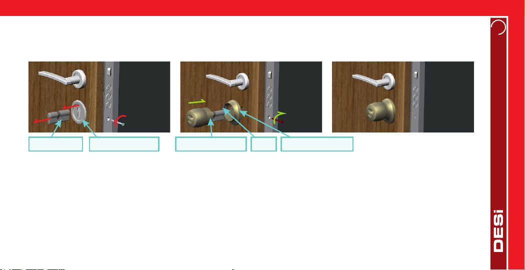
2.1.2. Installing The Device With Plastic Cover (For professional installers only)
If the cover of the door is not a part of cylinder defender (if it is used just to cover the disturbancies around the cylinder hole)
follow the instructions below to install the device:
If the cover of the door is used to install the defender, follow the instructions below to install the device:
- Remove the old cylinder.
- Remove cover of the door, the metal holder of cover and the defender.
- Adjust the screw lengths according to the new distance between defender and the cover of the door when the metal holder is
not used. (There are two adjustable screws in the box)
- Install cover of the door and defender with new screws adjusted in previous step.
- Install the motorized cylinder with cover spring and plastic cover.
(Please look to the next page for related illustrations.)
1.STEP
Remove
the cylinder
and cover
of the door.
2. STEP
Install the
motorized
cylinder with
cover spring
and
cover.
Old Cylinder Cover of the door Motorized Cylinder
That‘s
it!
Spring Cover of the device

8
Old Cylinder Metal
Holder
Cover
of the Door
Cover of The Door Motorized
Cylinder Cover
Spring
Defender
Screws Defender
(outside)
Adjusted
screws Defender
(outside)
Plastic Cover
1.STEP
Remove
the old
cylinder.
2.STEP
Remove the cover
of the door,
metal
holder of
cover and
defender.
3.STEP
Adjust the length
of two screws
out of
the box.
4.STEP
Install the cover
of the door
with adjusted
screws without
using metal
holder.
5.STEP
Install
the motorized
cylinder with
cover spring
and cover.
That’s
it!
i
This installation is recommended for porfessional installer only, due to needed technical knowladge about door and lock.
Cover
of The Door

9
3. ADMINISTRATIVE ACTIONS / SETTINGS
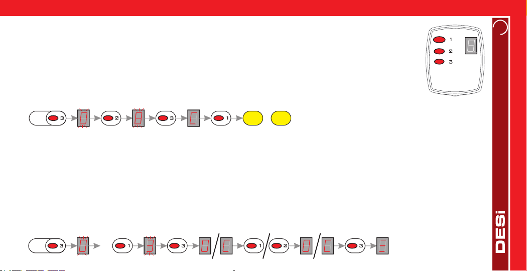
3.1. ENROLLING NEW REMOTE CONTROLLER
- Press 3rd button of master rc till “0" flashes on the display.
- Press 2nd button of master rc three times. “6" will be flashing on the display.
- Press 3rd button of master rc. “L” will be appeared on the display.
- Press 1st button of master rc. The cylinder will give a long (5 sec) and a short warning tone one after the other.
- Just after short warning tone, press 1st button of new remote controller
till you hear 2 warning tones from the cylinder.
In this way, the new remote controller will be enrolled to the device. Schematic representation of operation is as follows:
Master RC
3.2. DELETING ALL THE REMOTE CONTROLLERS
- Press 3rd button of master rc till “0" flashes on the display.
- Press 2nd button of master rc two times. “7" will be flashing on the display.
- Press 3rd button of master rc. “d” will be shown on the display.
- Press 1st button of master rc. The motorized cylinder will give a long (10 sec) and two short warning tone one after the other.
In this way, all the remote controllers (except the master rc) would be deleted from the device.
Schematic representation of operation is as follows:
3s 3X 5s Bp Bp Bp Bp
3s 2X 10s Bp Bp Bp
Before using your motorized cylinder, Direction of locking/unlocking (p.10) and Number of turns (p.10) should be adjusted.
i

10
Master RC
3.3. ADJUSTING THE DIRECTION OF LOCKING / UNLOCKING
- Press 3rd button of master rc till “0" flashes on the display.
- Press 1st button of master rc one time. “1" will be flashing on the display.
- Press 3rd button of master rc. Either “r” or “L” will be shown on the display.
- For counter-clockwise locking, choose “L” by pressing 1st button, for clockwise locking, choose “r” by pressing
2nd button and than press 3rd button to confirm selection. Three lines will be shown on the display.
After first locking or unlocking operation done by master rc, selected settings will be applied to the system.
Schematic representation of operation is as follows:
3.4. ADJUSTING THE NUMBER OF TURNS
- Close the door and press 3rd button of master rc till “0" flashes on the display.
- Press 1st button of master rc two times. “2" will be flashing on the display.
- Press 3rd button of master rc. “o” will be shown on the display.
- Press 1st button of master rc. The motorized cylinder will give a long (3 sec) warning tone and it will lock and unlock the door.
In this way, motorized cylinder learns the number of turns of the locking mechanism.
Schematic representation of operation is as follows:
3s
3s 2X 3s Bp Lock and Unlock
11
3.5. REPORTING NUMBER OF REMOTE CONTROLLERS IN THE MEMORY
- Press 3rd button of master rc till “0" flashes on the display.
- Press 2nd button of master rc one time. “8" will be flashing on the display.
- Press 3rd button of master rc. “C” will be shown on the display.
- Press 1st button of master rc.
The motorized cylinder reports number of remote controllers (and other wireless devices enrolled to the
motorized cylinder) as warning signals. Schematic representation of operation is as follows: Master RC
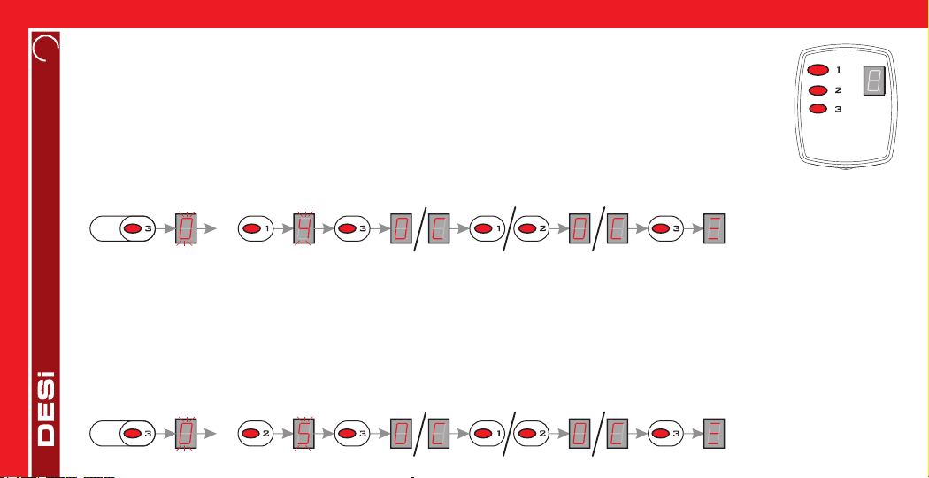
3.6. ADJUSTING BUZZER SOUND
- Press 3rd button of master rc till “0" flashes on the display.
- Press 1st button of master rc three times. “3" will be flashing on the display.
- Press 3rd button of master rc. Either “O” or “C” will be shown on the display.
- For disabling buzzer sound, choose “C” by pressing 1st button, for enabling buzzer sound, choose “O” by pressing 2nd button
and than press 3rd button to confirm selection. Three lines will be shownon the display.
After first locking or unlocking operation done by master rc, selected settings will be applied to the system.
Schematic representation of operation is as follows:
3s Bp Bp
...
3s 3x
12 3.7. NIGHT MODE AVAILABILITY (For detailed information about Night Mode see 4.2.a)
- Press 3rd button of master rc till “0" flashes on the display.
- Press 1st button of master rc four times. “4" will be flashing on the display.
- Press 3rd button of master rc. Either “O” or “C” will be shown on the display.
- For disabling “capability to shift night mode”, choose “C” by pressing 1st button, for enabling it, choose “O” by
pressing 2nd button and than press 3rd button to confirm selection. Three lines will be shown on the display.
After first locking or unlocking operation done by master rc, selected settings will be applied to the system.
Schematic representation of operation is as follows:
3s 4x
3.8. ADJUSTING SEMI-AUTOMATIC WORKING
- Press 3rd button of master rc till “0" flashes on the display.
- Press 2nd button of master rc four times. “5" will be flashing on the display.
- Press 3rd button of master rc. Either “O” or “C” will be shown on the display.
- For disabling semi-automatic working, choose “C” by pressing 1st button, for enabling semi-automatic working, choose “O” by
pressing 2nd button and than press 3rd button of master rc to confirm selection. Three lines will be shown on the display.
After first locking or unlocking operation done by master rc, selected settings will be applied to the system.
Schematic representation of operation is as follows:
3s 4x
Master RC
13
4. USAGE
4.1. UNLOCKING AND OPENING THE DOOR
If you press the 2nd button of rc, system automatically unlocks and opens the door.
You can unlock/open the door by using the knob or the key as well. If semi-automatic working is enabled (see 3.8),
when you rotate the knob or the key to unlocking way, it will sense the movement and continue automatically.
1
2 3
User RC
4.2. LOCKING THE DOOR
If you press the 3rd button of rc, system will automatically lock the door one turn.
If you press the 1st button of rc, system will automatically lock all the turns.
You can lock the door by using the knob or the key as well. If semi-automatic working is enabled (see 3.8), when you rotate the
knob or the key to locking way, it will sense the movement and lock the door one turn.
4.2.a NIGHT MODE
Night mode is a security option which temporarily disables remote controllers. In this way, the door can only be opened by knob
or the key.
iTo use Night Mode, 3.7 NIGHT MODE AVAILABILITY and 3.8 ADJUSTING SEMI-AUTOMATIC WORKING (p.12)
settings need to be enabled. If any of them is disabled, the motorized cylinder cannot shift to Night Mode.

14
1
2
To shift the motorized cylinder to night mode:
- Close the door and turn the knob through locking way. The motorized cylinder will lock the door one turn.
- Turn the knob again through locking way. It will lock all the turns.
In this way, the motorized cylinder will shift to Night Mode. To exit from night mode, turn the knob through unlocking way. It will
automatically unlock the door and shift to normal working mode. You can shift to or exit from night mode by using key as well.
If you hear triple warning tone after any operation (locking/unlocking), or if the motorized cylinder rotates too
slowly, you need to replace the batteries. To change them, open knob screw and remove knob (pull outward),
uninstall old batteries and install new batteries (watch polarities). Put knob back and tighten knob screw.
i
- The motorized cylinder uses 5x AA size 1,5 V Alkaline or Lithium batteries.
- Lithium batteries last about 2 times longer than alkaline batteries.
- Do not use old and new batteries or different types of batteries together.
- If you are changing batteries, change them all. Use high quality batteries.
5. MAINTENANCE
You can clean the surfaces with soft fabric. Do not use water or corrosive chemicals. Do not touch to electronic parts of the
device with a conducting metal or sharp object.
5.1. REPLACING MOTORIZED CYLINDER’S BATTERIES
Due to chemical structures of lithium batteries, the period between hearing the low battery signal and stop working is shorter
compared to alkaline batteries. If you are using lithium batteries, you need to change the batteries immediately when you hear
low battery warning.

15
6. TROUBLESHOOTING
IF THE MOTORIZED CYLINDER CANNOT FULLY LOCK/UNLOCK THE DOOR
There can be high friction on the lock or latch bold. It may be caused by sag of the door or unadjusted locking mechanism. Check
if you can open the lock and latch with a key easily. If there is a problem on door or lock, that need to be fixed.
Batteries of motorized cylinder may be weak. Change with new batteries.
IF DOOR IS NOT OPENED EVEN THE KNOB IS ROTATING
There is a problem related with connection between motor and cylinder. Call your dealer and ask for service.
IF RC IS NOT WORKING
The motorized cylinder maybe in night mode. (see 4.2.a)
The battery of remote controller may be weak. Change the battery with new one.
5.2. REPLACING REMOTE CONTROLLER’S BATTERY
If the controlling range of rc is getting shorter, battery of rc need to be changed. To change the battery, untighten battery
screws and open the cover carefully. Change the battery by watching polarities, close the cover and tighten the screws. It is
recommended to change the battery by a professional technician. User and master rc are using 3V 2032 type lithium battery.

Desi Alarm and Security Systems Inc.
Topkapı Maltepe Cd. Anadolu Sk. N:1 Bayrampaşa, İstanbul / TURKEY
T. +90212 501 72 72 F. +90212 576 64 77
MANUFACTURER
Other manuals for Utopic 2
1
Table of contents
Other DESi Door Lock manuals


Popular Door Lock manuals by other brands


FingerTec
FingerTec Keylock 8800 user guide

Assa Abloy
Assa Abloy mFlipLock standard Assembly and operating instructions

Stuv
Stuv 3.31.270 Series Assembly instructions

INVITED
INVITED SMARTLOCK Installation guide & user manual

Stanley
Stanley QEL 200 user guide

Assa Abloy
Assa Abloy E100 Mounting instructions