Besam PowerSwing User manual

Besam PowerSwing
Installation, Adjustment and Troubleshooting Manual
Complies with ANSI/BHMA A156.10 standard for Power Operated Pedestrian Doors and A156.19
standard for Power Assist and Low Energy Power Operated Doors. UL 325 Listed.
US23-0922-02 10-21-2002
© Copyright 2006 Besam Entrance Solutions. May not be reprinted or reproduced without permission.

PowerSwing US23-0922-022
© Copyright 2006 Besam Entrance Solutions. May not be reprinted or reproduced without permission.
Improperly adjusted doors can cause injury and equipment damage.
Inspect door operation daily using safety checklist in Owner’s Manual and at
door.
Have door adjusted as described in Owner’s Manual.
Safety devices must be in place and operational.
Have door inspected at least once a year by an AAADM inspector, and always
after any adjustment or repair.
In the following manual, the word:
Caution means that injury or property damage can result from failure to
follow instructions;
Note indicates important steps to be followed or important differences in
equipment.
Revision
At each revision all revised pages will get a new updated issue number (year-
month-day). The first leaf (pages 1 and 2) will always have the same issue num-
ber as the revised pages. Changes will be marked with a vertical line in the margin.
The table below shows the latest issue numbers.
Page Issue No. Page Issue No. Page Issue No.
01 10-21-2002
|
02 10-21-2002
|
03 10-21-2002
|
04 01-18-2001
05 01-18-2001
06 10-21-2002
|
07 01-18-2001
08 10-21-2002
|
09 01-18-2001
10 10-21-2002
|
11 10-21-2002
|
12 10-21-2002
|
13 10-21-2002
|
14 10-21-2002
|
15 10-21-2002
|
16 01-18-2001
17 10-21-2002
|
18 01-18-2001
19 10-21-2002
|
20 10-21-2002
|
21 10-21-2002
|
22 10-21-2002
|
23 10-21-2002
|
24 10-21-2002
|
25 10-21-2002
|
26 01-18-2001
27 01-18-2001
28 01-18-2001
29 01-18-2001
30 01-18-2001
31 10-21-2002
|
32 10-21-2002
|
33 01-18-2001
34 01-18-2001
35 10-21-2002
|
36 01-18-2001
37 01-18-2001
38 01-18-2001
39 01-18-2001
40 10-21-2002
|
41 01-18-2001
10-21-2002

3PowerSwing US23-0922-02
© Copyright 2006 Besam Entrance Solutions. May not be reprinted or reproduced without permission.
Contents
Revision 2
Important information 4
Introduction 5
Function description 5
Technical specifications 6
Models 7
Part Identification & Options 8-10
Mechanical installation 11-19
Installation with adapter plate 13-14
Operator with arm system PUSH 15-17
Operator with arm system PULL 18-21
Electrical connection 22-25
Control units 22
Connection of control units 23-25
Start-Up 26-31
Connection of activation units… 28
Connection of mat to extension unit EXA 29
Connection of OPD to extension unit EXA 29
Connection of Push & Go to extension unit EXA 30
Connection of Airing position to extension unit EXA 30
Connection of PassPort presence sensor 31
Cover 32
Installation on fire doors 33-38
Troubleshooting 39-40
Installation examples 41
10-21-2002

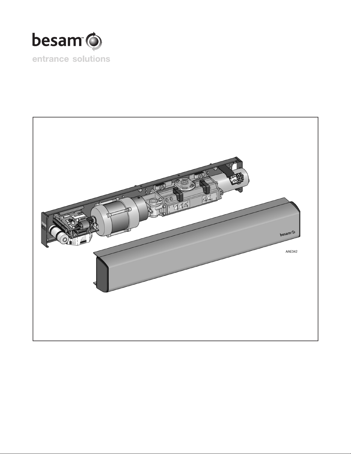
01-18-2001 PowerSwing US23-0922-024
© Copyright 2006 Besam Entrance Solutions. May not be reprinted or reproduced without permission.
Important I nformation
Important Notice!
To avoid bodily injury, material damage and malfunction of the product,
the instructions contained in this manual must be strictly observed dur-
ing installation, adjustment, repairs and service etc. Only Besam trained
experts should be allowed to carry out these operations.
Radio and Television Reception
This equipment generates and uses radio frequency energy and if not
installed and used properly, that is, in strict accordance with the manufac-
turer’s instructions, may cause interference to radio and television recep-
tion. It has been designed to comply with the emission limits in accord-
ance with EN 500811 (US market FCC Part 15) which are designed to
provide reasonable protection against such interference in a residential
installation. However, there is no guarantee that interference will not
occur in a particular installation. If this equipment does cause interference
to radio or television reception, which can be determined by turning
the equipment off and on, the user is encouraged to try to correct the
interference by one or more of the following measures:
Re-orient the receiving antenna.
Relocate the receiver with respect to the equipment.
Move the receiver away from the equipment.
Plug the receiver into a different outlet so that equipment and receiver are
on different branch circuits.
If necessary, the user should consult the dealer or an experienced radio/
television technician for additional suggestions.
Note!
Instructions, design, specifications and illustrations which are contained
in this manual are not binding. Rights reserved for changes without previ-
ous notice.

01-18-2001 5PowerSwing US23-0922-02
© Copyright 2006 Besam Entrance Solutions. May not be reprinted or reproduced without permission.
Introduction
This manual contains the necessary details and instructions for the installation,
maintenance and service of the Besam PowerSwing.
The Besam PowerSwing is suitable for most types of external and internal swing
doors. The operator can be mounted to walls on either side of the door for pull
or push action and is suitable for single or double doors fitted with butt hinges or
center pivots.
The motor, oil pump and hydraulic unit are combined into a compact unit mounted
alongside the control unit within the cover. The operator is connected to the door
leaf with a range of different arm systems.
Function Description
The Besam PowerSwing works electro-hydraulically. It opens with an AC-motor
that via a hydraulic unit and an arm system transmits the power to the door leaf.
The closing power is from a coil spring. The movement of the door is controlled
by limit switches and valve screws.
Opening
When an opening impulse is received by the control unit, the motor starts and
the hydraulic unit rotates the drive shaft and arm system (door) with high speed
towards open position. Before fully open position the speed is reduced to low
speed. The door stops and the motor rotation ceases when the selected door open-
ing angle is reached. This open position is kept by a hydraulic valve.
Closing
The spring closing starts when the hold open time has run out. Before fully closed
position the speed is reduced to low speed, which will be kept until the door is
completely closed. The door is kept closed by spring power. To overcome the
resistance of a striking plate a “lock kick” can be adjusted to required level.

PowerSwing US23-0922-026
© Copyright 2006 Besam Entrance Solutions. May not be reprinted or reproduced without permission.
Technical Specifications
Mains power 120 V AC ± 10 %, 60 Hz
fuse 10 A
Note!
Switch with clearly marked off-position, having a
contact separation of at least 3 (1/8'') mm in all
poles, must be incorporated in the fixed wiring.
The operator can also be plug-connected to a
wall socket.
Power consumption max. 230 W
Auxiliary voltage 13-20 V DC, 275 mA
24 V DC, 375 mA (stabilized)
Motor fuse F1 10 Amp (10 ATH)
Control fuse F2 1/2 Amp (500 mAT)
Recommended max. door weight Arm system PUSH
250 kg (550 lb) for door leaf width 1600 mm (63'')
Arm system PULL
100 kg (220 lb) for door leaf width 1400 mm
(55''). Higher door weights on request.
The PowerSwing complies with the door
weights/widths stated in the:
Controlled door closing,
EN 1154 sizes 3-6
Electrically powered hold-open device for
swing doors,
EN 1155
Coordination unit for rebated doors, EN 1158
Türschliesser mit Öffnungsautomatik
(Drechflügelantrieb)
DIN 18263-4 AU Grösse 3-6
ANSI/BHMA A156.10, A156.19
UL325/CUL325
SITAC 0166/99
Ambient temperature -30°C to +50°C (-22°F to 122°F)
Dimensions:
PowerSwing Length: 716 mm, 746-1600 mm *
(28-3/16", 29-17/32" – 63'')
PowerSwing-2 Length: 1435-3200 mm
(56 1/2" – 126")
Height: 110 mm (4-11/32")
Depth: 110 mm (4-11/32")
To be installed internally or externally with suitable weather protection.
* 716 is the European short header package.
746 allows for the operator to be mounted to the adapter plate with the addition of 2 cover
clips.
10-21-2002

01-18-2001 7PowerSwing US23-0922-02
© Copyright 2006 Besam Entrance Solutions. May not be reprinted or reproduced without permission.
Models
Two main models of the Besam PowerSwing are available:
•PowerSwing,
• PowerSwing-2, double door operators
The operators are non-handed and not dependent on the hinges. The operators suit
both pushing and pulling arm systems.
PowerSwing
The operator is offered standard in an oversize length which is field cut to required
length. Optionally length L may be specified to the factory as part of order. Pushing
arm system shown.
PowerSwing-2, double door operators
The designation PowerSwing-2 means that two operators are mounted under the
same cover to open one door each. The operator is offered standard in an oversize
length which is field cut to required length. Optionally length L may be specified
to the factory as part of order. Pushing and pulling arm system shown. It is also
possible to use two pushing or two pulling arm systems.

PowerSwing US23-0922-028
© Copyright 2006 Besam Entrance Solutions. May not be reprinted or reproduced without permission.
Part Identification & Options
1. Mounting plate
2. Motor/pump
3. Valve
4. Hydraulic unit
5. Drive shaft
6. Spring tube
7. Cable inlet
8. Main connection
9. Control unit, CSDA
10.Extension unit, EXA (option)
11.End plate
12.Programme selector,
PS3A (option)
13.Cover
14.Bearing sleeve
15.Cable holder
16.Adapter plate
17.Cover mounting clip
C Center line, drive shaft
L1
C Center line, hinge
L2
Arm system, PUSH P/N: 173 009 BK (173 883, Hybrid)
This arm systems is delivered with drive arm, telescopic part and door fitting. It is
used if the operator is installed on the wall on the opposite side of the door swing,
and approved for fire door application.
Arm system, PULL P/N: 100 125 BK
This arm system is delivered with drive arm, guide shoe and door fitting.
Arm system, PULL-P P/N: 100 134 BK
This arm system is delivered with drive arm, guide shoe door fitting, and panic
break-out.
10-21-2002

01-18-2001 9PowerSwing US23-0922-02
© Copyright 2006 Besam Entrance Solutions. May not be reprinted or reproduced without permission.
Part Identification & Options

PowerSwing US23-0922-0210
© Copyright 2006 Besam Entrance Solutions. May not be reprinted or reproduced without permission.
Part Identification & Options
10-21-2002

11PowerSwing US23-0922-02
© Copyright 2006 Besam Entrance Solutions. May not be reprinted or reproduced without permission.
Mechanical Installation
This instruction comprises the installation of the Besam PowerSwing with arm
systems PUSH which push the door open and PULL which pull the door open.
Always make sure, before commencing the installation, that the door leaf and the
wall are properly reinforced at the attachment points.
Base material Minimum requirements
Steel 5 mm (3/16")*
Aluminium 6 mm (1/4")*
Reinforced concrete min. 50 mm (2") from the underside
Wood 50 mm (2")
Brick wall Expansion-shell bolt, min. M6x85, UPAT PSEA
B10/25 min. 50 mm (2") from the underside
See also "Installation examples" page 37.
*Thin-wall profiles must be reinforced with rivnuts
Tools required
Torx T8, T10, T20 and T25
Metric hexagonal key 3, 4 and 6 mm.
Flatblade screwdriver, small
Torque wrench with metric Allen socket 6 mm.
Installation on double doors
If the operators are to be mounted at the same height with pushing and pulling arm
systems, the height is determined by the pulling arm system, PULL. The pushing
arm system PUSH must always have a shaft extension, minimum 50 mm (2"),
maximum 70 mm (2 3/4") to match the mounting heights visually.
Example: if PULL has a 20 mm (3/4") extension, the PUSH must have a 70 mm
(2 3/4") extension. If PULL has 0 mm extension, the PUSH must have a 50 mm
(2") extension.
For installation follow the instructions for the applicable arm system.
Note:
The short operator package requires the installer to follow the ”Mounting
Plate Applications” installation procedure. For jamb to jamb applications
(full length header box surface applied) the installer must use ”Adapter Plate
Application”.
10-21-2002

PowerSwing US23-0922-0212
© Copyright 2006 Besam Entrance Solutions. May not be reprinted or reproduced without permission.
Mechanical Installation
Door/Operator Handing
Operator Handing
Door Handing (Automatic Door Industry)
Door handing is determined by standing with your back to the hinges. The side to
which the door normally opens (right or left) is the handing of the door. The door
is an inswing door if it opens to the inside and an outswing door if it opens to the
outside. The diagram to the left shows a right-handed outswing door.
Door Handing (Architectural Hardware Industry)
You may occasionally see references to terms such as ‘right hand reverse’ or ‘left
hand reverse.’ See diagram below for definition, paying particular atten-tion to the
location and placement of the hinge. Because of the varied hardware items appli-
cable, a swing door type has to be identified by a specific hand. The hand of a door
is always as viewed from the exterior side of a door. Reverse designations apply to
such hardware as rim type panic exit devices and latch locks which have a beveled
latch for locking purposes on doors that swing out.
10-21-2002

13PowerSwing US23-0922-02
© Copyright 2006 Besam Entrance Solutions. May not be reprinted or reproduced without permission.
Mechanical Installation
Installation with Adapter Plate
Note: Consider all power wire entry locations and secondary signaling wires
before preparing adapter plate.
Preparation of Adapter Plate
1. Cut the adapter plate to correct length, L.
2. Establish the ”hinge center line”, C
L1.
3. Mark and drill the six holes ø 8 mm (5/16”) for the fixing of the adapter plate
to the jambs and header. Countersink two holes as shown in the illustration
so that the screw heads do not interfere with the operator.
4. Mark, drill and thread 6 holes for the fixing of the operator and 4 holes for
fixing of the cover mounting clips with end plates.
Locating and Creating Slot in the Cover for the Drive Shaft
1. Use a 1” hole saw to cut the round hole for the output spindle.
2. Use a sabre saw to make two straight cuts.
10-21-2002

PowerSwing US23-0922-0214
© Copyright 2006 Besam Entrance Solutions. May not be reprinted or reproduced without permission.
Mechanical Installation
Installation
Establish the installation height X (PUSH) or Z (PULL) considering the arm
system to be used:
– Pushing arm system, PUSH, see page 15.
– Pulling arm system, PULL/PULL-P, see page 18. Note! If required, change
the direction of rotation before mounting the operator, see page 17.
1. Fix the adapter plate to the wall.
2. Mount the cover mounting clips with end plates.
3. Mount the operator.
Arm System, PUSH
Mount arm system in accordance with the instructions and illustrations on pages
15-16.
Arm System, PULL
Mount arm system in accordance with the instructions and illustrations on pages
18-19.
Arm System PULL-P
Mount arm system in accordance with the instructions and illustrations on pages
18-19 together with separate instructions enclosed with the arm system.
10-21-2002

15PowerSwing US23-0922-02
© Copyright 2006 Besam Entrance Solutions. May not be reprinted or reproduced without permission.
Mechanical Installation, PUSH
Operator with Arm System PUSH
Establish the Installation Height
Establish the installation height X which is the distance from the underside of the
wall to the underside of the mounting plate or adapter plate for jamb to jamb. Mark
distance X on the wall. X can be between 2 – 87 mm (3/32” – 3-7/16”) depending
on the shaft extension used; none, 20, 50 or 70.
Note: 2 mm (3/32”) achieves a flush unit when cover is mounted.
Mounting the Drive Unit (Mounting Plate Application)
1. Stick the template to the wall aligned with the hinges and with the underside of
the mounting plate aligned with the mark on the wall.
2. Ensure that the template is perfectly horizontal. Punch and drill the four mount-
ing holes and the two holes for the door fitting.
3. Remove the template.
4. Tap, plug or reinforce with rivnuts and screw the drive unit tight.
Mounting the Door Fitting with Telescopic Part
1. Remove the door fitting from the arm system.
2. Screw the door fitting to the door leaf tight.
Hinge center line
Drive shaft center line
10-21-2002

01-18-2001 PowerSwing US23-0922-0216
© Copyright 2006 Besam Entrance Solutions. May not be reprinted or reproduced without permission.
Mechanical Installation, PUSH
Mounting the Drive Arm
1. Mount the drive arm and adaptor on the operator drive shaft at an angle of 90° to
the wall.
2. Ensure that the teeth of the adaptor engage fully with the operator shaft but
especially with the drive arm, so they are not damaged when the drive arm is
tightened. Tighten the screw to a torque of 25 Nm (19 lbf . ft).
➀ Adaptor
➁ Drive arm
Adjusting the arm system (Spring tension preloading)
1. Open the door and connect the door fitting with the drive arm (do not tighten
the lock screws).
2. Close the door and keep it closed.
3. Turn the drive arm until the telescopic part is at an angle of 90° to the door.
4. Tighten the telescopic part with the lock screws.
➀ Telescopic part
➁ Drive arm

17PowerSwing US23-0922-02
© Copyright 2006 Besam Entrance Solutions. May not be reprinted or reproduced without permission.
Mechanical Installation, PUSH
Installing the Door Stop
1. Install door stop to top side of output spindle to prevent door from extending
beyond 90º.
2. Mount door stop when door is in open position with a clearance of 2 mm (2/32”)
as shown below. Fine adjust, if necessary, on limit switch and/or on armsystem.
Note! If door stop cannot be mounted on top of operator, remove washer and
mount stop on bottom side between shaft and arm system.
Checking the Door Movement
Open the door by hand to its maximum extent. Then let it close of its own accord.
Check that the opening/closing movements are smooth and free.
Continue on page 20 for electrical installation.
10-21-2002

01-18-2001 PowerSwing US23-0922-0218
© Copyright 2006 Besam Entrance Solutions. May not be reprinted or reproduced without permission.
Mechanical Installation, PULL/PULL-P
Operator with Arm System PULL/PULL-P
If the operator is not ordered as an “operator package with arm system PULL”
the direction of rotation must be reversed.
Changing the Direction of Rotation
1. Mount the washers and screws in the drive shaft, one from each side.
2. Dismantle the screws (4 pcs) from the bearing sleeves on both sides.
3. Fit the tools in the holes, one from each side and turn both bearing sleeves
simultaneously approx. 165° until the setting lines in the bearing sleeves are
aligned with the setting lines in the housing.
4. Remount the four screws in the bearing sleeves and dismantle the washers and
screws.
➀Washer and screw
➁Screw (4 pcs)
➂Bearing sleeve (2 pcs)
➃Tool
➄Setting lines

19PowerSwing US23-0922-02
© Copyright 2006 Besam Entrance Solutions. May not be reprinted or reproduced without permission.
Mechanical Installation, PULL/PULL-P
Establish the Installation Height
Establish the installation height Z which is the distance from the top of the door
to the underside of the mounting plate. Mark distance Z on the wall. Z can be 46,
66, 96 or 116 mm (1-13/16”, 2-19/32”, 3-3/4” or 4 9/16”) depending on whether a
shaft extension is used or not.
Mounting the Drive Unit (Mounting Plate Application)
1. Stick the template to the wall aligned with the hinges and with the underside
of the mounting plate aligned with the mark on the wall.
2. Ensure that the template is perfectly horizontal. Punch and drill the four mount-
ing holes and the two holes for the door fitting.
3. Remove the template.
4. Tap, plug or reinforce with rivnuts and screw the drive unit tight.
Hinge center line
Drive shaft center line
10-21-2002

PowerSwing US23-0922-0220
© Copyright 2006 Besam Entrance Solutions. May not be reprinted or reproduced without permission.
Mechanical Installation, PULL/PULL-P
Mounting the Drive Arm and Door Fitting, PULL/PULL-P
Note! For installation of PULL-P (panic break-out) see also illustration (drawing
No. 655990) page 21.
1. Connect the main power (see page 21).
2. Open the door to an angle of 90°.
3. Give constant impulse by strapping the impulse inputs on the control unit. The
drive shaft turns to a factory-set position.
4. Slide the guide shoe into the door fitting.
5. Using dimensions shown from hinge center line, mount the door fitting to the
door panel fastening securely.
6. Mount the drive arm on the drive shaft with the door in unchanged position
(90°). Ensure that the teeth of the adaptor fit well with the operator drive shaft
and the drive arm.
7. Tighten the screw to a torque of 25 Nm (19 lbf . ft).
8. Slide the arm stop against the guide shoe and then back 20 mm (3/4"). The
guide shoe must not hit the arm stop during normal operation. Fasten the arm
stop.
9. Remove the strapping. The motor turns off and the door closes.
10. Snap on the end plates to the door fitting.
Checking the Door Movement
Push the door to its fully open position. Check that it can open to the required
angle and that the guide shoe runs easily in the track of the door fitting. Check also
that the complete arm system operates without problems.
10-21-2002
Other manuals for PowerSwing
1
This manual suits for next models
1
Table of contents
Other Besam Door Opening System manuals