DeVi-Stairlifts UP User manual

V2.1 28-5-2019
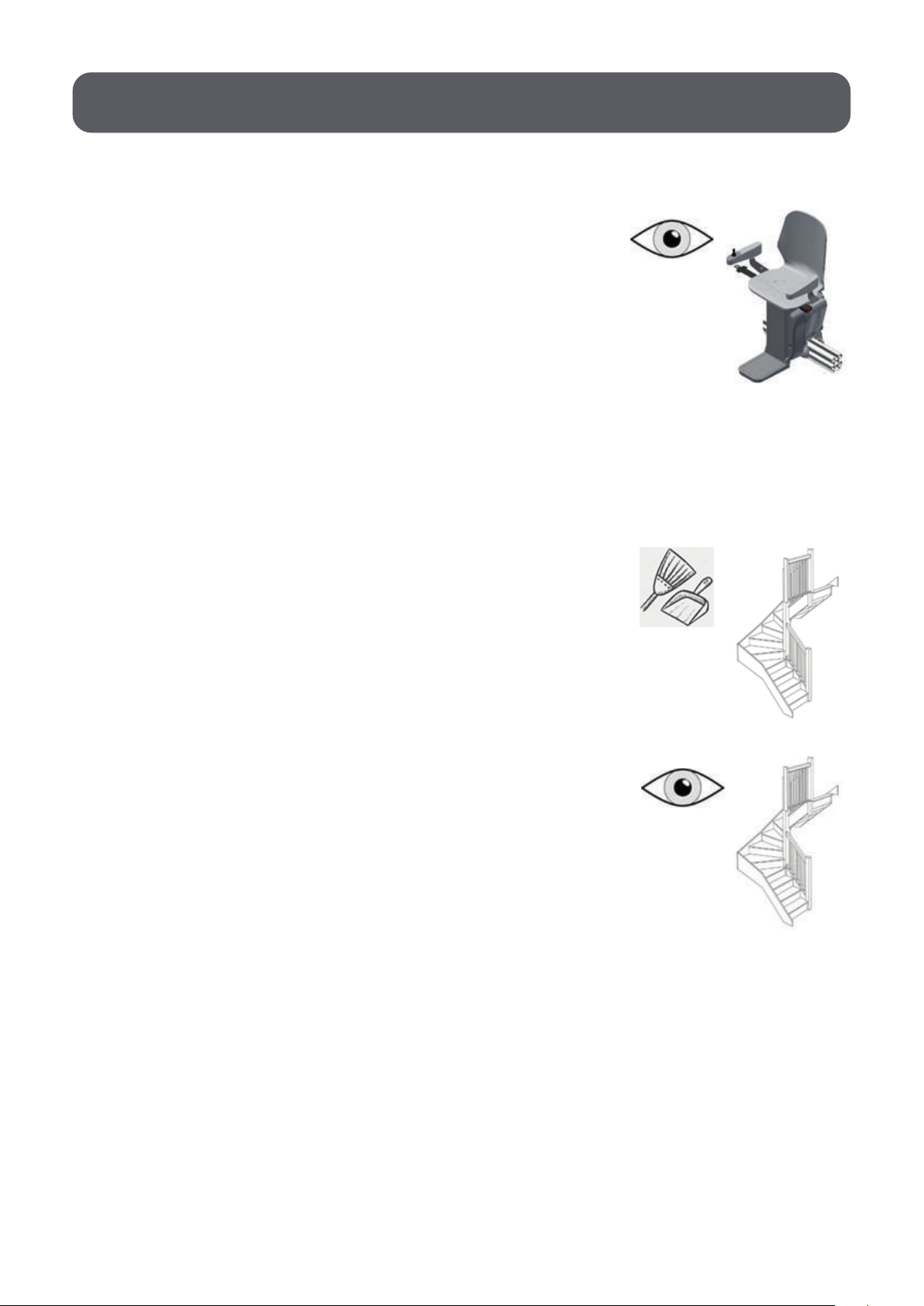
UP stairlift installation manual

IMPORTANT NOTE!!
Read this document carefully
before installation of the stairlift.
Ignoring the instructions
presented in this document, can
create unsafe situations with
accidents as a possible consequence.
This UP stairlift is
FOR INDOOR USE ONLY
The warranty for the UP Stairlift void
if the unit is installed or maintained by
anyone other than an authorized UP dealer.

3
Design the rail
Saw the rail to length
Place the supports and rail as in the drawing
Place the rack in the rail and grease it
Place the stairlift
Configure the stairlift with the app
mount the endcaps onto the rail
Controll the functions
Explain the functions to the customer
Fill in the form
Clean the workarea

4
Health and Safety Hazards 5
Box content 6
Installation tools 7
Pre-installation procedure 8
Installation
Basic before installing the rails 9
Installing the rails 10
Connecting different segments 10
Rail mounting 11
Installing the charging stations 13
Installing the carriage 15
Safety Checks 19
Control check 19
Remote control check 19
Safety sensors check 19
Limit check 20
Seat swivel check 20
Footrest check 20
Check for smooth travel 20
Labelling 20
Demonstrate UP stairlift to the User 21
Maintenance 21
Avoiding unsafe installation 21
Index

The risk of falling down the stairs
The risk of body parts or loose clothing getting trapped
The risk of direct and indirect electrical contact
The risk of injuries caused by inappropriate use of tools
The risk of tools falling down the stairs
Use of necessary protection (safety glasses etc)
Never use worn tools
The risk of tripping hazards on the staircase
5
Health and safety hazards

CHECK CARTON CONTENTS FOR SHIPPING DAMAGE IMMEDIATELY
UPON RECEIPT.
• Check the carton contents for shipping damage as soon as the box arrives.
• Verify the contents against the packing list BEFORE leaving the shop for
the installation site.
• Report any discrepancies to DeVi-Stairlifts immediately.
• Damage claims must be reported within 5 days.
BOX
• complete carriage with seat
• straight rail
• rail curve 5 degree
• rail mountings
• charging stations
• screws, nuts, bolts, rings
• gear rack
• wiring for charging stations
• wiring with connector for charger
• endplate
• charger
• ruber blocks for wiring
Option:
• remotes
• bendingtool
6
Box content

Always check if you have all necessary
parts and tools before travelling to the installation site.
• power drill + segments for drill bits
• drill bits: appropriate for oor (eg. concrete, hardwood, tiles)
• crosshead bit for power drill type
• drill 4 appropriate for the staircase steps 4mm
• grinder with steel grinding disc
• small ratchet (stubby + DR) 1/4 + small (50mm) and large extension (100mm)
• inbus cap 5 and 6 for small and large ratchet
• torx bit T30 for small and large ratchet
• wrench 13
• cap 13
• rubber hammer
• flat screwdriver SL4x80 + 0,4x2.0
• crosshead screwdriver PH2x38 + PH1x80
• torque wrench
• wire stripper
• wire cutter
• stanley knife
• small rubber hammer with a handle of 20mm
• spirit level
• aluminium saw
• steel saw
• file
• vacuum cleaner
• angle measure tool
• steel hammer
• concrete drill (when needed)
• extension cord
• grease
7
Installation tools
Before starting the installation of the stairlift perform the following
preparations and checks:
1. Visually inspect the plastic covers.
Check for damages that might have occurred
during transport. In case of any damages do not
install the lift and contact an authorized dealer.
2. Check the received components with the stated components of the box content
in this manual to discover missing parts. In case of a missing part, contact
an authorized dealer.
3. If the carriage is undamaged and all components
are present, clear the staircase from any obstructive
objects and objects that might be damaged during
the installation.
4. Identify already existing damages to the staircase
and its surrounding. Make note of these damages,
this is to be able to check for damages made during
installation.
8
pre-Installation procedure

9
Measuring the rail.
Download the manual ‘UP webshop manual’ from www.upwebshop.com.
Go to the part webshop, login, click on Downloads and there you can find the
manual. Or click HERE if you are reading this manual digital.
Then follow the steps for measuring the stairs as described. When filling in
these measurements the tool will provide you with a drawing. An example of such
a drawing can be seen in figure 1. Use this drawing as a basis for the installation
of the rail. For example to get the lengths of the straight parts and the amount of
turn segments required for the turns.
(fig. 1)
The installation of the stairlift can be done in different phases. These
phases are installing the rail, installing the charging station and finally
installing the carriage.
install-drawing-1-f12bd63ad3
SIDEVIEW
R1
B1
R2
B2
R3
B3
R4
B4
R5
B5
R6
B6
R7
B7
R8
S1
S2
S3
S4
S5
S6
S7
S8
S9
S10
S11
S12
S13
Page 2 of 4
install-drawing-1-f12bd63ad3
Item Name Size Description
R1 Rail 216mm AB010000(l=216)
B1 Bend 40° AB070000(8x) + AB030000
R2 Rail 584mm AB010000(l=584)
B2 Bend 40° AB070000(8x) + AB030000
R3 Rail 366mm AB010000(l=366)
B3 Bend 75° AB070000(15x) + AB030000
R4 Rail 25mm AB010000(l=25)
B4 Bend 90° AB070000(18x) + AB030000
R5 Rail 264mm AB010000(l=264)
B5 Bend 50° AB070000(10x) + AB030000
R6 Rail 490mm AB010000(l=490)
B6 Bend 15° AB070000(3x) + AB030000
R7 Rail 2708mm AB010000(l=1850 + l=858) + AB020000
B7 Bend 35° AB070000(7x) + AB030000
R8 Rail 1163mm AB010000(l=1163)
S1 Support 0mm AB040000
S2 Support 383mm AB040000 + AB050000 + AB060000(3x)
S3 Support 144mm AB040000 + AB060000
S4 Support 293mm AB040000 + AB050000 + AB060000(2x)
S5 Support 127mm AB040000 + AB060000
S6 Support 286mm AB040000 + AB050000 + AB060000(2x)
S7 Support 0mm AB040000
S8 Support 218mm AB040000 + AB060000(2x)
S9 Support 166mm AB040000 + AB050000 + AB060000
S10 Support 114mm AB040000 + AB060000
S11 Support 80mm AB040000 + AB060000
S12 Support 0mm AB040000
S13 Support 0mm AB040000
X Rack 7400mm AB000600(l=1850mm 4x)
X Charging cable 12000mm AB080000(l=6000mm 2x)
Page 3 of 4
Installation

The rail is built up from the different segments. The following steps explain
how to connect the different segments and mount the rail to the stairs.
Connecting different segments
1. Start by sawing the straight parts to the desired
length as measured before ordering the stairlift.
Deburrs the rail after cutting.
2. When you need an longer straight rail then 1.85 meters
you have to connect two parts togheter by using the rail joint. (AB020000)
See figure 2 and 3. You need two connectors, eight bolts M8x16 DIN 934,
eight nuts M8 ISO 4017 and four pins.
3. Take the straight parts and attach a rail curve segment to either end of it,
except for the beginning and the end of the rail. These straight parts get a turn
segment at only one of their ends. The straight and turn segments are connected
by four DIN 7500-1 M6X20 bolts (AB030000) at the location of the four blue
arrows. See figure 4 for this step. Note: make sure that the orientation of the
curve segments is correct to get the right alignment of the parts.
10
(fig. 2) (fig. 3)
(fig. 4)
install-drawing-1-f12bd63ad3
Item Name Size Description
R1 Rail 216mm AB010000(l=216)
B1 Bend 40° AB070000(8x) + AB030000
R2 Rail 584mm AB010000(l=584)
B2 Bend 40° AB070000(8x) + AB030000
R3 Rail 366mm AB010000(l=366)
B3 Bend 75° AB070000(15x) + AB030000
R4 Rail 25mm AB010000(l=25)
B4 Bend 90° AB070000(18x) + AB030000
R5 Rail 264mm AB010000(l=264)
B5 Bend 50° AB070000(10x) + AB030000
R6 Rail 490mm AB010000(l=490)
B6 Bend 15° AB070000(3x) + AB030000
R7 Rail 2708mm AB010000(l=1850 + l=858) + AB020000
B7 Bend 35° AB070000(7x) + AB030000
R8 Rail 1163mm AB010000(l=1163)
S1 Support 0mm AB040000
S2 Support 383mm AB040000 + AB050000 + AB060000(3x)
S3 Support 144mm AB040000 + AB060000
S4 Support 293mm AB040000 + AB050000 + AB060000(2x)
S5 Support 127mm AB040000 + AB060000
S6 Support 286mm AB040000 + AB050000 + AB060000(2x)
S7 Support 0mm AB040000
S8 Support 218mm AB040000 + AB060000(2x)
S9 Support 166mm AB040000 + AB050000 + AB060000
S10 Support 114mm AB040000 + AB060000
S11 Support 80mm AB040000 + AB060000
S12 Support 0mm AB040000
S13 Support 0mm AB040000
X Rack 7400mm AB000600(l=1850mm 4x)
X Charging cable 12000mm AB080000(l=6000mm 2x)
Page 3 of 4
Installing the rail

4. Complete the curve by adding segments (AB070000)
until the desired turn angle is reached. Every segment
is 5°. Remember that two segments of the turn are
already in place. At the red arrows a DIN 912 M6X30
screw should be placed with a DIN 934 M6 nut, with
the help of a fixing torque. See figure 5.
5. Eventually, the turn as displayed in figure 6 is
obtained. The turn can be made in every direction
by changing the orientation of the turn segments.
However, between two consecutive turns a straight
part of at least 25 mm should be present.
Rail mounting
Depending on the distance from the stairs, three different pieces can be
used for mounting the rail. Rail support short (fig. 7), Rail support medium
(fig. 8) and Rail support long (fig. 9). These pieces can be combined to get
the desired length for the mount.
AB040000 AB050000 AB060000
1. First determine the distance of the rails to the stairs or ground.
If possible, only use the rail support short otherwise combine
mounts to get the right length.
For the protection of the stairs, use little pieces of cardboard
under the rail supports until you mount them to the stairs.
2. When combining rail supports always have two of the rail
support short on the bottom of the combination. Fix them by
combining a bolt M8x16 DIN 934 and nut M8 ISO 4017
at the blue arrows (fig. 10). Combine the longer rail mounts
by laying them on top of each other and fixing them at the
red arrows (fig. 10). The desired length can be obtained
by changing the holes at which the mounts are connected
to each other.
11
(fig. 5)
(fig. 6)
(fig. 8) (fig. 9)
(fig. 10)
(fig. 7)

3. Slide a nut M8 ISO 4017 in both of the two slots pointed
out by the blue arrow in figure 11.
4. Fix the mounts by a bolt M8x16 DIN 934 through the last
hole of a mount and the nuts M8 ISO 4017 placed in step 3.
See figure 12, for the holes to put the bolts through.
Make sure that the triangular mounts can be placed entirely
and securely on the ground or a step of the stairs. Do not fix
the bolt entirely until this is achieved.
5. When a good location for the rail support is found,
fully fix the bolt from step 4. Besides, fix the rail
support short to the floor or the step of the stairs.
Drill first a hole in the stairs with drill 4 or 3.5.
Then use four screws 6x30MM through the
holes pointed out in figure 13.
6. Place rail supports close before and close after each turn. For the straight
parts place rail supports approximately every meter. However, do not place
the rail supports at the two ends of the rail yet, this would block the access
for the charging station.
7. When the rail is mounted, the gear rack can be put in.
The rail can be fixed with ST3.9x16 DIN 7504 screws
in the outer gaps. They are pointed out in figure 14.
Always make sure that the screws are placed as far as
possible against the side of the slot. Start with the gear
rack 5 cm from the beginning of the rail so that it is
easier to place the carriage on the rail.
Do not place screws in the holes in the middle, these
are for the pinion to drive. When there is a curve, the
rack can be bent with a bending tool to get the
right shape for the turn. Place the screws every
10 cm and before and after every curve.
12
(fig. 11)
(fig. 12)
(fig. 13)
(fig. 14)
1
0
0mm

Installing the charging stations
1. Put two ferrules on the black and red wires
with the connector for the charger (fig. 15).
2. Measure the length that is necessary to connect two charging stations
plus 20 cm extra and cut a red and black wire on this length. Put ferrules on
either end.
3. Put the black and red wire with the connector in the first charging
station and use a screwdriver to fasten the wires.
Also put the long black and red wire in the charging station and use a
screwdriver to fasten the wires (fig. 16).
4. The long wires have to go through the complete rail from the beginning
till the end.
In the straight rail you have to put the wires through the bottom (fig. 17).
At the turns you have to mount the wires also at the bottom and use the
rubber blocks to fasten the wires on the rail (fig. 18).
MAKE SURE THAT YOU PUT THE RED WIRE AT THE +
AND THE BLACK WIRE AT THE -
13
(fig. 17) (fig. 18)
(fig. 15)
(fig. 16)

5. You have to place the charging stations approximately at the beginning and
the end of the rail and at points that is handy for the customer. To place the
charging station on the rail, you have to shove two nuts M8 ISO 4017
in the back slot at each straight part of the rail. The slot is shown in figure 19.
6. Fix the charging station with two bolts M8 ISO 4017, located at
the red arrows in figure 18 and put it in the nuts from step 5.
Make sure that the charging station is located sufficiently
far from the end of the rails, such that the center of the
carriage can reach it.
7. Repeat step 5 and 6 for placing the charging station at the
end of the rail.
8. Plug in the furreles, that are placed on the red and black wire,
that come out at the end of the rail in the charging station.
Fasten the furreles with a screwdriver.
9. When the charging stations are fixed on the right locations,
you can use the connector, that is on the wire from the first charging
station, to plug in the charger. Then the charger can be plugged in
a wall outlet.
10. The last step is to ground the rails. Attach a ring with a wire on a
screw of a rail support. Then attach the wire to a grounding point.
14
(fig. 19)

Installing the carriage
1. The carriage is delivered fully assembled on a piece of rail with short rail
supports to level it. Grease the geat rack before usage. To get it out the box,
remove all other parts from the box and remove the bolts from the rail support.
Get the carriage out of the box including the rail part.
2. When you have a horizontal landing at the bottom,
or top place the rail from the box next to the rail on
the stairs. Put the connecting part in the rail from
the stairs and then push the carriage slow from the
rail part on the other side over the connecting plate,
otherwise the osg will be activaded.
See figure 20 and 23, then go to step 4.
3. When you have a dropnose you have to place the carriage at the top of
the stairs.
3.1To make it easier to get the carriage upstairs you have to remove
the seat. This is possible by removing the four bolts M8x16 DIN 934,
see figure 21.
3.2 Carry the carriage and the seat upstairs.
3.3 When you have a horizontal landing at the top, place the rail from
the box next to the rail on the stairs. Put the connector in the rail from
the stairs and then push the rail from the box on the other side over
the connector. See figure 20 .
3.4 When you have a straight landing at the top, it is the same as
the horizontal landing but than you have to lift the carriage to the right
angle to put the ‘box’ rail on the connecting part (fig. 22).
15
(fig. 20)
(fig. 21) (fig. 22)

16
(fig. 23)

4. Flip the main switch at the back of the stairlift (fig. 24).
5. Push the on/off button on the armrest (fig. 25).
6. Download the ‘UP configuration app manual’ from
www.upwebshop.com. Go to the parts webshop, login, click on Downloads
and there you can find the manual. Or click HERE if you are reading this
manual digital.
Install the remote app on your phone, this app can also be found on
www.upwebshop.com on the downloads page or click HERE.
Make sure that your bluetooth is on (fig. 26). Select the UP-xxxxxx in your
bluetooth. When you select the UP you need to put in a password.
The password is 1234. Open the app on your phone. Push the button “Connect”.
Push the button QR and scan the QR-code that is on the right side of the UP.
Now your phone is ready to use as a remote for the stairlift.
When you do not use the app for 30 seconds you need to re-scan the
QR-code.
17
(fig. 24)
(fig. 25)
(fig. 26)

10. Put the seat back on the carriage with the four bolts M8x16 DIN 934. When
neccesary. (fig. 21)
11. Remove the ‘box’ rail and connecting part from the stair rail.
12. When the stairlift is all set, end stops have to be placed on either end of
the rails. This is done with four DIN 7500-1 M6X20 bolts through the four
holes of the end plate. (fig. 30)
13. Configurate the stairlift using the UP conigurate app.
14. The final step is to mount te QR code,
or the optional remote controls, on the wall.
It has to be mounted at the beginning and
at the end of the rail. You can use
double-sided tape to mount the QR code
on the wall. For the remote control you have
to use the remote control bracket.
18
(fig. 30)
7. As soon as the app has loaded all data from the lift (fig. 27), you can start
to control the lift. You can set each motor in motion in the override
section (fig. 28 + 29) of the app. Ride the stairlift on to the rail.
8. With the lift on the rails, you can start calibrating the stairlift.
Once the configuration has started, you are taken through the app by a
number of steps.
(fig. 27) (fig. 28) (fig. 29)

Congratulations you just installed the UP Stairlift!
After installation various safety checks will have to be performed, notes need to be
taken from these safety checks.
Control check
1. If the carriage is upstairs push the joystick in the downward direction.
The stairlift should start to travel down. When releasing the button the
stairlift should stop.
2. If the carriage is downstairs push the joystick in the upward direction.
The stairlift should start to travel up.When releasing the button the
stairlift should stop.
Remote control check
Push remote config ON inside the configurate app to add remotes.
1. Press the downward button on the app or on the optional remote.
The stairlift should travel down. When releasing the button the stairlift should stop.
2. Press the upward button on the app or on the optional remote.
The stairlift should travel up. When releasing the button the stairlift should stop.
Safety sensors check
1. Move the stairlift upwards with the joystick,
app or remote and push the cover of the footrest.
The stairlift should stop.
2. Move the stairlift downwards with the joystick,
app or remote and push the cover of the footrest.
The stairlift should stop.
3. Move the stairlift upwards with the joystick,
app or remote and push the cover of the carriage.
The stairlift should stop.
4. Move the stairlift downwards with the joystick,
app or remote and push the cover of the carriage.
The stairlift should stop.
19
(fig. 31)
Safety checks

20
5. Move the stairlift upwards with the joystick, app or remote and push the cover
of the wheels. The stairlift should stop.
6. Move the stairlift downwards with the joystick, app or remote and push the
cover of the wheels. The stairlift should stop.
Limit check
1. Move the stairlift to the top end of the rails. The stairlift should
stop automatically when it reaches the charging station.
2. Move the stairlift to the bottom end of the rails. The stairlift
should stop automatically when it reaches the charging station.
Seat swivel check
1. Drive the stairlift to the top charging station. When the stairlift reaches
the charging station, hold the joystick in the upward direction. The chair
should start to swivel when it is configurated.
2. Push the joystick in the opposite direction, the chair should swivel back.
3. Drive the stairlift to the bottom charging station. When the stairlift reaches
the charging station, hold the joystick in the downward direction. The chair
should start to swivel when programmed.
4. Push the joystick in the opposite direction, the chair should swivel back.
Footrest check
1. Push the armrest up. The footrest should go down.
2. Push the armrest down. The footrest should go up.
Check for smooth travel
Drive the stairlift up and down the rails, ensure that the ride is smooth and stable.
Furthermore check if the stairlift stops in the desired positions.
Labelling
Check if all the labels and warning stickers are in place.
Other manuals for UP
1
Table of contents
Other DeVi-Stairlifts Stairlift manuals


