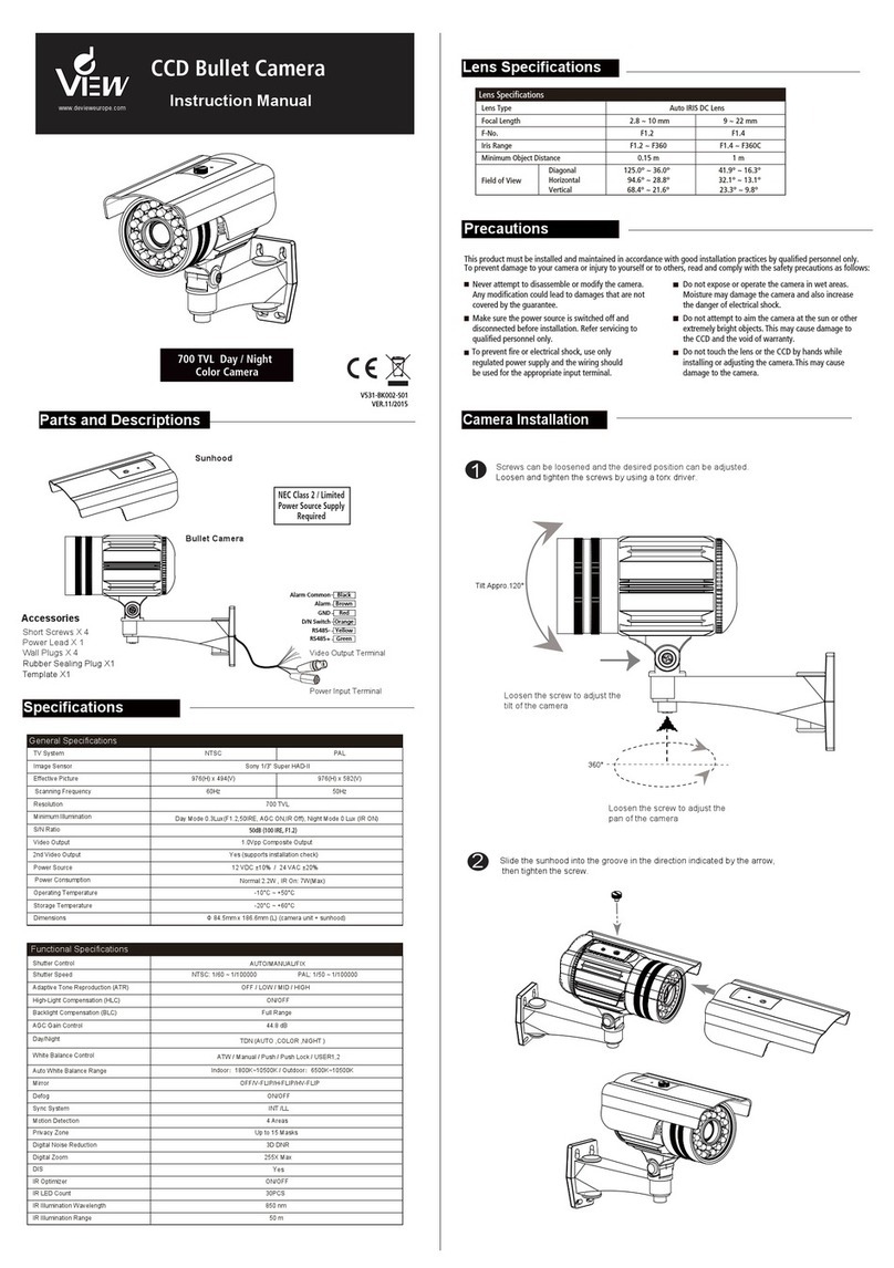
DeView VDM Series User manual

VDM Series
Metal Vandal Dome
Enclosure Installation Guide
RoHS
Regulatory Compliance
Emissions
Immunity
FCC part 15 Class B
CE: EN55011
ICES-003
EN55022
CISPR 11
CISPR22
ANSI C63.4
CE: EN50130-4
FCC COMPLIANCE:
This equipment has been tested and found to comply with the limits for a Class B
digital device, pursuant to Part 15 of the FCC Rules. These limits are designed to
provide reasonable protection against harmful interference in a residential installation.
This equipment generates, uses and can radiate radio frequency energy and, if not
installed and used in accordance with the instructions, may cause harmful interference
to radio communications.
However, there is no guarantee that interference will not occur in a particular
installation. If this equipment does cause harmful interference to radio or television
reception, which can be determined by turning the equipment off and on, the user is
encouraged to try to correct the interference by one or more of the following measures:
• Reorient or relocate the receiving antenna.
• Increase the separation between the equipment and receiver.
• Connect the equipment into an outlet on a circuit different from that to which the
receiver is connected.
• Consult the dealer or an experienced radio / TV technician for help.
CISPR 22 WARNING:
This is a Class B product. In a domestic environment this product may cause radio
interference in which case the user may be required to take adequate measures.
POWER SUPPLY REQUIREMENTS:
For use with listed Audio / Video product and only connected to 15W or less power
supply.
*Power supply should be a NEC Class 2/LPS supply.
EQUIPMENT MODIFICATION CAUTION:
Equipment changes or modifications not expressly approved, the party responsible for
FCC compliance, could void the user’s authority to operate the equipment and could
create a hazardous condition.
This class B digital apparatus complies with Canadian ICES-003.
Cet appareil numérique de la classe B est conforme à la norme NMB-003 du Canada.
Hardware Kit Contents
• 3/4” Rubber Grommets x 2
• Screw Packs x 2
• M4 Torx Screw Driver x 1
• M2 Allen Key x 1
• Wire-ended Power Adaptor Lead x 1
Template
Surface Mount
Create four holes of diameter ¼” (7mm) at template positions ‘T3’.
Use 4 x wall plugs and 4 x (no.12 x 1½”) screws.
When mounting externally, use a rubber o-ring at each mounting hole
in the base to ensure moisture resistant seals.
Cable Entry (in base cable entry case)
When use the base cable entry, create a hole of diameter 3/4”NPT (19mm)
at template positions ‘T4’.Cable is threaded out the base.
Using screws to install out ring:
Create three holes at template positions ‘T1’ of diameter 1/5” (5.2mm) and
insert a wall plug into each.Use three screws.
Flush Mount
Create an aperture in the mounting surface to a diameter of 5.5” (140mm) as
indicated by ‘T2’.
Using locking arms (see Installation Method B overleaf) :
Place the enclosure (with the locking arms retracted) into the opening.
Use a cross-head screwdriver to rotate the locking screws until the locking
arms, firstly splay out, and then tighten against the inner face of the mounting
surface.
Tighten the screws sufficiently to compress the o-ring moisture seals located
underneath the screw heads, however:
DO NOT OVERTIGHTEN.
T3
T3
T3
T4
T1
T2
Outer Ring T1
T1
T3
• Handle the camera with care. Do not abuse the camera. Avoid striking or
shaking it. Improper handling or storage could damage the camera.
• Irrespective of whether the camera is in use or not, never faces it towards
the sun. Use caution when operating the camera in the vicinity of spotlights
or other bright lights and light reflecting objects.
Do not operate the camera beyond its temperature, humidity or power
source ratings. Please refer to the environmental information provided
overleaf.
Precautions
Please visit our website for more information
www. deview.com

Large Rubber Gasket
Dome Cover
Outer Ring
Cable Entry
Secure Screws
Dome Base
Rubber o-rings to
maintain moisture
seal when fixing
externally.
Rubber o-rings to
maintain moisture
seal when fixing
externally.
Video-Power Cables
Power Input
Video Output
Create an aperture in the mounting surface to
a diameter of 5.5” (140mm) as indicated by
“T2” (see template overleaf ).
Turn silver-colored screws counter-clockwise
by half a turn to extend the locking arms and
then clockwise to tighten them against the
mounting surface (see image B1).
In case of dust and moisture ingress, always
use the large rubber gasket on the dome base
befor installing the dome base (see image B2).
Tighten the screws sufficiently to compress the
o-ring moisture seals located underneath the
screwheads.
Note: Do Not Overtighten.
Flush Mount using Locking Arms.
B3
Locking Arm
Locking Arm Base Cable Entry
Side Cable Entry
Method B:
Flush Mount Using Locking Arms
Locking Screw
Extending the Lock Arm
with Screw Driver
Mount Large Rubber Gasket on
Dome Base before Installation
Large Rubber Gasket
Locking Arms
B1
B2
Allen Head
Locking Screw
Allen Key
D3
Rubber Grommet
Methods for Mounting the Enclosure
There are two main ways to mount and fix the dome enclosure:
A: Surface mount using the outer ring.
B: Flush mount using locking arms.
Note: Always use the template provided.
When mounting externally using the four base holes, use the supplied rubber o-rings
within the mounting holes to ensure moisture resistant seals. Ensure that the cable
entry through either conduit point is suitably sealed against moisture ingress.
Regardless of whether the locking arms are used for installation or are folded away
(in favor of another installation method), always ensure that the locking arm screws
are tight enough to compress the rubber o-rings to maintain the moisture seal.
Method A : When Mounting Externally
Base Cable Entry
Side Cable Entry
Use either the base cable entry (see image D1)
or side cable entry (see image D4) as required.
Carefully remove the appropriate cable entry
sealing plug before installation.
If mounting indoors and conduit is not used,
cables should be passed through a slotted
rubber grommet to prevent dust ingress
(see image D3).
Note: If the side conduit entry is not used, make
sure that the cable entry point is secured with
the outer ring sealing plug (see image D2).
Do Not Overtighten the Locking Screws.
D1
D2
Video-Power Cables
Select Proper Cable Entry
Using Side Cable Entry
When surface mounting and using the
side cable entry (see image D4), first
remove the cable entry sealing plug in
the dome base.
Pull out the outer ring sealing plug so
that the video-power cables can pass
through the outer ring (see image D4).
D5
Outer Ring
Sealing Plug
Outer Ring
D4
C
Torx
Screw
Driver
Cover Screws
Remove the Dome Cover
Use the supplied large torx driver to
loosen, if required, (but not remove)
the four cover screws.
The screws are captive and will be
retained in the lid.
E1
Make all connections is complete before
mounting Camera Module on Dome Base
Fit the Camera Assembly
Gimbal Securing Screws
Camera
Assembly
GCDNH/GCDPH Day/Night Cameras:
Plug the multi colored wire from the camera directly
into the wire that is attached to the power supply
(see image E1).
GCDNH/GCDPH Wide Dynamic Range versions
Cameras:
Connect the white wire with the red stripe to the center
connector on the service jack (see image E3).
Remove the multi color wire that is plugged into the
power control board (6 wire) and replace with the
(5 wire) lead that comes with the camera, then proceed
to plug the camera into this lead (image E3).
E4
E2
Connecting GCDNH/GCDPH
Day/Night Camera
Connecting GCDNH/GCDPH
Wide Dynamic Range Camera
Installing the Camera Module on Dome Base
Place the complete camera
assembly onto the three
mounting pillars.
Insert and tighten the three
gimbal securing screws
(see image E4).
Note:
Do Not Overtighten
the Screws.
Service Jack
Board
Power Control Board
E3
WDR Camera Module
Connector to
Service Jack Board
Connector to
Power Control Board
Adjust the Camera Position
Remove the camera liner and adjust the camera
position (image F1).On the two sides of the module has
positioning screws.
Slightly loosen the positioning screws if the module is
too tight to rotate (image F2).
Rotate and pan the camera chassis to the required
position. Slightly tighten the positioning screws on the
both sides (see image F3).
Note: Do Not Overtighten the Positioning Screws.
Replace the camera liner when the camera is correctly
positioned.
Replace the Dome Cover
Replace the dome cover and use the supplied torx
screw driver to tighten the four cover screws
Install the camera liner
on the camera module
Camera Liner
Positioning Screw
F1
F2
F3
90°
360°
360°
Adjusting the camera position
Positioning Screw
Installing the Dome on the Mounting Area
All mounting access positions should be
sealed until they are ready to be used.
For example, when externally mounting the
housing with the outer ring, first remove the
base cable entry sealing plug that
correspond to the template marks “T4”.
This can be accomplished by using a
cross-point screw driver.
Open three holes correspond to the
template mark “T1” for the outer ring.
Then open four holes at template
positions “T3” for installing the dome base.
The template is in page overleaf.
Note: Ensure the large rubber gasket is always placed under the lip of the dome
when mounting.
Outer Ring
Large
Rubber Gasket
Dome Base
Other DeView Security Camera manuals
DeView
DeView ATMP7W User manual
DeView
DeView Tamper Proof User manual
DeView
DeView MD3CN12M User manual
DeView
DeView CQ Series User manual
DeView
DeView 690HTVL-E User manual
DeView
DeView BTP12H37V12L User manual
DeView
DeView MD4SP70 User manual

DeView
DeView CR Series User manual
DeView
DeView D410-THRE3V12L User manual
DeView
DeView CR Series User manual
