manuals.online logo
Brands
  1. Home
  2. •
  3. Brands
  4. •
  5. DeView
  6. •
  7. Security Camera
  8. •
  9. DeView 690HTVL-E User manual

DeView 690HTVL-E User manual

Vandal Proof Dome Camera
ediuGresU
stnetnoCtiKerawdraH
,
.tcudorpsihtgnisahcruprofuoyknahT
.ylluferacteehssihtdaeresaelp,tinusihtgnitarepoerofeB
,ecnailpmocyrotaluger,stnetnocegakcapedulcniteehssihtnidedivorpnoitamrofnI
plehotsaosnoosdnasnoitartsulliaremac,snoitacificepssnel,snoitacificepsaremac
dnasnoitacificepsehttahtetonesaelP.tinusihttuobarettebwonkuoy
stnemevorpmirehtrufrofegnahcottcejbuseratinus
ihtfoecnaraeppa
teehSsihttuobA
ehtotreferesaelp,noitacificepss’tinuehttuobasnoitpircseddeliatedroF
.relaedlacolruoytcatnocesaelp,yriuqnironoitamrofniynaroF.tnetnocgniwollof
without prior notice.
ecnailpmoCyrotalugeR
Emissions FCC part 15 Class B
CE: EN55011
ICES-003
EN55022
CISPR 11
CISPR22
ANSI C63.4
Immunity CE: EN50130-4
RoHS
FCC COMPLIANCE:
This equipment has been tested and found to comply with the limits for a Class B digital device, pursuant to Part 15 of the
FCC Rules.These limits are designed to provide reasonable protection against armful interference in a residential installation.
This equipment generates uses and can radiate radio frequency energy and,if not installed and used in accordance with the
instructions, may cause harmful interference to radio communications. However, there is no guarantee that interference will
not occur in a particular installation.
If this equipment does cause harmful interference to radio or television reception, which can be determined by turning the
equipment off and on, the user is encouraged to try to correct the interference by one or more of the following measures:
• Reorient or relocate the receiving antenna.
• Increase the separation between the equipment and receiver.
• Connect the equipment into an outlet on a circuit different from that to which the receiver is connected.
• Consult the dealer or an experienced Radio/TV technician for help.
CISPR 22 WARNING:
This is a Class B product. In a domestic environment this product may cause radio interference in which case the user may be
required to take adequate measures.
POWER SUPPLY REQUIREMENTS:
For use with listed Audio/Video product and only connected to 15W or less power supply.
*Power supply should be a NEC Class 2 / LPS Supply.
EQUIPMENT MODIFICATION CAUTION:
Equipment changes or modifications not expressly approved by seller.
The party responsible for FCC compliance could void the user’s authority to operate the equipment and could create a
hazardous condition.
This class B digital apparatus complies with Canadian ICES-003.
Cet appareil numérique de la classe B est conforme à la norme NMB-003 du Canada.
V531-DH011-S00
Ver.08/2011
•
•
•
•
•
•
•
•
Quick install adaptor x 1 (Optional)
Torx driver x 1
D5 fixing screws x 3
T6 fixing screw (for T6 fixing screw) x 1
Wall plugs x 3
Power lead x 1
Cable entry sealing plug
(1/2”, for quick install adaptor use) x 1
Cable entry sealing plug
(3/4” ,for dome base use) x 1
A
B
A: Focus Adjuster
B: Field of View Adjuster
weivrevOaremaC
*Please refer to the following “Camera
Adjustment” for more information about
the connection.
stnemtsujdaaremaC.snoisrevRDWotelbaliava,draoBecivreSsetartsulligniwollofehT
.draoblortnocDSOlanretxenagnisuybedamebnac
C: Control Board Connector
OSD control board
kcajecivreS:D
UP
Down
noitacificepSaremaC uneMDSOaremaC
Exit Menu
Monitor
Outdoor
Exposure D/N Control AUTO
Night Mode
Off
Shutter Mode
D/N Switch
LCD
CRT
GAMMA
Setup Iris
Video I/O
SYNC
Title
Save/Restore Restore User Settings
Save User Settings
Restore Factory Settings
Reset Camera
System Info
Presets WD-Normal
Indoor
Normal
White balance Mode
Viewing PTZ
FLIP
Day/Night Setup
On
D/N Threshold
D/N Delay
D/N Limit
B/W + Burst
B/W
Auto
Off
AWB
ATW Normal
ATW Extended
Manual Kelvin
R/B
Meter Mode
Lens Select
DC Gain
AI Threshold
Manual/DC
Video Standard PAL/NTSC
LL
INT
V-Phase
INT2
Title Display
Camera Title
On/Off
Title Position
Normal
Backlight
Normal Meter
Presets
Adjust Normal Enable Zones
Adjust WD-Normal
Zones
Presets
Adjust Safe Area
Adjust CTR Spot
Adjust Lower 1/3
Up-Left
UP-Right
Up-Center
Down-Left
Down-Right
WD-Normal
CTR Spot
Safe Area
Lower 1/3
WD-Normal
CTR Spot
Safe Area
Lower 1/3
690HTVL-E Day / Night
Color Camera
noitacificepSsneL
Exposure Control
Backlight Compensation
AWB
White Balance Control
Digital Noise Reduction
Sync System
Day & Night
Gamma Compensation
Full Range
2800k~9100k
INT / L.L
0.45
Functional Specifications
Standard Range
EX Range
3D Motion Adaptive (0~255)
2000k~11000k
SDN (ON, OFF, AUTO)
htoB;lacitreV;latnoziroHpilF
Digital PTX 1X~8X
TV System
Image Sensor
Resolution
Scanning Frequency
Effective Picture Element
Mount Type
Video Output
S/N Ratio
Min. Illumination
Storage Temperature
Operating Temperature
Power Consumption
Power Source
NTSC PAL
Pixim Seawolf 1/3” Sensor
758(H)x540(V) 758(H)x540(V)
>50dB
Surface and Flush Mount
1.0Vpp 75ΩBNC unbalanced
12VDC ±10% / 24VAC±20%
2.88 W Max
-10°C~+50°C
-30°C~+80°C
General Specifications
Wide Dynamic Range Control 102dB Typical, 120dB Max.
ATW Normal, AWB
690 HTVL-E
Gain Control, Shutter Control, Wide Dynamic, Manual
60Hz 50Hz
50IRE: 0.1Lux F1.2
Digital Slow Shutter up to 32X
Focal Length
F-No.
Iris Range
Minimum Object Distance
Field of View
Diagonal
Horizontal
Vertical
3.3~12mm 9~22mm
F1.4
F1.4~F360
1m
41.9º~16.3º
32.1º~13.1º
23.3º~9.8º
Camera adjustments and programming
In addition to the levers for Focus (A) and Field of View (B),
all settings are made by keys on the OSD service board.
1. With power applied to the camera and a video monitor connected, press and hold
the MENU key for three seconds to access the top level menu. A map of the menu
options are shown in the following Camera OSD Menu.
2. Use the arrow keys on the control board to navigate around the OSD menu and use the
MENU key to confirm your selections.
3. Once programming is complete choose Exit from the menu,
otherwise any changes made will be lost.
4. If required, the camera can be reset to factory defaults by selecting
RESET in the OSD menu.
Note:
DPC (Dead Pixel compensation): The camera has a feature that can cover most dead pixels
that could occur over time. Select DPC under the special menu, Cover the lens to black it
out then press the menu key - this may take up to 30 seconds to complete,.
Once complete the camera will automatically take you to back to the menu structure.
If you gain access to the DPC menu and do not want to perform the function,
press the up or down button to escape and you will be returned to the previous screen.
125.7º~29.9º
F1.4
F1.4~F360
0.5m
89.8º~23.9º
63.6º~17.9º
3.0~9.0mm
F1.4
F1.4~F360
0.5m
115.4º~39.8º
90.3º~31.9º
66.4º~23.9º
Locking Arms
IJ
K
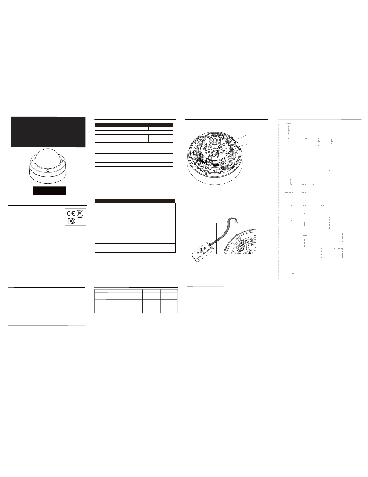
Use the quick install adaptor on a wall or ceiling application
1/2”Rubber
Grommet
Video-Power
Cables
Mounting Surface
Mount with the quick install adaptor.
Mounting Surface
Mounting externally using the template
Mounting externally using required cable entry
3/4”
Rubber Grommet
Cable Entry
Installation
The following optional accessories are available for specific applications.
Contact your retailer or local representative for details.
Using the quick install adaptor (Optional):
When mounting the dome to a ceiling or wall using the quick install adaptor, use the template to
cut a hole as the circle marked “T2” with a hole cutter.
Install the adapter into the mounting surface by turning the screws anti-clockwise by approx 1 turn
to release the arms and then turn clockwise to pull the arms towards the flange and secure the
adapter to the mounting surface (see image I).
Push the cables through the opening and 1/2” rubber grommet.
Make sure the grommet is properly installed on the adaptor to prevent dust ingress (see image J).
Removing the dome cover and the camera module
Use the supplied large torx driver to loosen the four cover screws. The screws
are captive and will be retained in the lid (image A).
Loosen the gimbal securing screws to remove the camera assembly (image B).
Open the required cable entry
Use either the base cable entry (C1) or side cable entry (C2) as required. When surface
mounting and using the side cable entry (C2) open either the large (C3) or small (C4)
knock-out within the outer ring to the required size by cutting away excess material with a
hole cutter. The outer ring can be rotated so that either of the knock-outs lie alongside the
side cable entry, as required. Unused cable entries should be blanked with sealing plugs
(C5). If the conduit entry is not used, cables should be passed through a slotted cable
grommet (C6) to prevent dust ingress.
For external applications, conduit should be used to carry cables into the housing.
When mounting the dome to a ceiling or wall using screws, first knock out the four base
screw access holes that correspond to the template marks “T1”. This can be done by
using a cross-point screwdriver(see image D).
Create four holes on the mounting surface using template marks “T1”; then create an
aperture using the template mark “T4” for the 3/4”base cable entry.
When flush mounting or surface mounting
using the outer ring, ensure that the large
rubber gasket (see image F) is in place
under the lip of the dome enclosure.
Connect the wiring
Feed the preconnected main lead through one of the cable access points and connect it
to your video output and power input cables.
A wire-ended adaptor lead (E1) is supplied for use with power supply cables that are not
terminated with an appropriate power connector.
For 12VDC operation: Connect the red lead to “+” and the black lead to “-”.
12VDCGND
Video Output
Power Input
Wire-ended adaptor lead
E
E1
Red: +12VDC
Black: 0VDC
IMPORTANT: If the dome is being mounted externally, use a suitable sealant
around the cable entry hole to ensure a moisture resistant seal. This will prevent
water vapour from the connected conduit condensing inside the housing.
IMPORTANT: If the dome is being mounted externally using the four base
holes, use the supplied rubber o-rings within each of the four mounting
holes of the dome base to ensure moisture resistant seals.
Note: Do Not Overturn the Screws.
Mounting the Enclosure with Optional Accessories
AB
Create an aperture in the mounting surface to a diameter of 4.3” (110mm) as
indicated by “T3” (as showen in template). Turn silver-colored screws
counter-clockwise by half a turn to extend the locking arms and then clockwise to
tighten them against the mounting surface (see image F).
Using Locking Arms on the dome base for Flush mount.
Locking Arm
Locking Arm
3/4”Base Cable Entry
1/2” Side Cable Entry
Flush Mount Using Locking Arms
Locking Screw
Extending the Locking arms with screw driver.
Rubber Gasket
Locking Arm
D
Note: In case of dust and moisture ingress, always use the large rubber gasket
on the dome base before installing the dome base.
Tighten the screws sufficiently to compress the o-ring moisture seals located
underneath the screwheads.
Do Not Overtighten.
Replace the Camera Module
Tighten the gimbal screws to reinstall the camera assembly with a screw driver.
F
Install the Dome Liner
on the Camera Module
G
Install the camera liner
Carefully fit the camera liner over the
camera base so that it snaps into
place (as shown in image G), and do
not obstruct the camera lens.
Replace the Dome Cover
Replace the dome cover using the index marks (as shown in
image H) to align it and tighten the torx screws to secure the lid.
Do not overtighten.
H
The dome cover
The dome base
index mark
index mark
Mount on a US single gang Box:
When mounting the dome to the box,
carefully remove the screws on the box.Install
the 3/4“ grommet on the base to prevent dust
ingress, then push the cables through the
dome base and 3/4” rubber grommet.
Mount the dome base on the box and reinstall
the two screrws on te securing ositions.
Tighten the screws sufficiently on the box
(position T5, see image K).
K
US Single Gang Box
Dome Base
T5
T5
Mount on a pre-installed US single gang box
3/4” Rubber
Grommet
Securing
Position
(T5)
(T5)
Securing
Position
C1
C2
C3
C4
C6
C5
Csmall
knock-out
large
knock-out
rubber grommet
sealing plug
side
cable entry
base
cable entry
Adjust the camera position
To adjust the tilt angle, first loosen the 2 screws on the gimble
(See image right) make your adjustments then retighten the
screws.
The focus and range of the lens can be adjusted (depending
on the lens, see instructions overleaf).
Note: Do not attempt to adjust the camera position by holding
the lens as this will cause damage to the camera.
Make adjustments by tilting and rotating the gimble assembly. The dome cover
The domThe dom
e dom
dom
dom
The dom
om
m
m
m
e
e
e
e c
e cover
e c
e
e
Screw
Gimble
Gimble
T1
T2
Template
Cable Access Using Base Cable Entry
When the cables are threaded through the mounting
surface, create an apture of 3/4” (26.5mm) indicated
“T4”.
Note: When mounting the dome on a surfce with
the four T1 screws, use one of the side knock-outs
as indicated for cable entry
(see installation guide overleaf ).
Note: When mounting on a US Singal Gang Box,
use the pre-drielled securing holes in the dome base
as indicated “T5”.
Do Not Open the aptures at position “T5”.
Surface Mount (on a wall or ceiling)
Using Quick Install Adaptor:
Create an aperture in the mounting surface to a
diameter of 1.5” (56mm) as indicated by “T2”.
Using Locking Arms:
Create an aperture in the mounting surface to a
diameter of 4.3” (105mm) as indicated by “T3”.
Using Screws:
Create four holes at template positions ‘T1’, use the
screws and plugs provided in the screw kit where the
mounting surface is appropriate.
Cable Access
T1
T1
T1
T5
T3
T5
US Singal Gang Box
US Singal Gang Box
T4

Other DeView Security Camera manuals

DeView D410-THRE3V12L User manual

DeView

DeView D410-THRE3V12L User manual

DeView CQ Series User manual

DeView

DeView CQ Series User manual

DeView Tamper Proof User manual

DeView

DeView Tamper Proof User manual

DeView CR Series User manual

DeView

DeView CR Series User manual

DeView CR Series User manual

DeView

DeView CR Series User manual

DeView ATMP7W User manual

DeView

DeView ATMP7W User manual

DeView MD4SP70 User manual

DeView

DeView MD4SP70 User manual

DeView CCD User manual

DeView

DeView CCD User manual

DeView VDM Series User manual

DeView

DeView VDM Series User manual

DeView BTP12H37V12L User manual

DeView

DeView BTP12H37V12L User manual

DeView MD3CN12M User manual

DeView

DeView MD3CN12M User manual

DeView CR Series User manual

DeView

DeView CR Series User manual

Popular Security Camera manuals by other brands

Axis Q6074 installation guide

Axis

Axis Q6074 installation guide

Vivotek AT-CAB installation guide

Vivotek

Vivotek AT-CAB installation guide

Swann A851 Pro-Series instruction manual

Swann

Swann A851 Pro-Series instruction manual

Vista VBC28V12MHDA installation manual

Vista

Vista VBC28V12MHDA installation manual

X10 AIRSIGHT XX36A Quick installation guide

X10

X10 AIRSIGHT XX36A Quick installation guide

Panasonic BL-C230A installation guide

Panasonic

Panasonic BL-C230A installation guide

Digital Watchdog Infinity V3367WTIR user manual

Digital Watchdog

Digital Watchdog Infinity V3367WTIR user manual

Novus NVIP-5H-4232M quick start guide

Novus

Novus NVIP-5H-4232M quick start guide

ACTi KCM-8111 user manual

ACTi

ACTi KCM-8111 user manual

Ildvr Digital Technology USA SC series user manual

Ildvr Digital Technology USA

Ildvr Digital Technology USA SC series user manual

Wirepath Surveillance WPS-DVR user guide

Wirepath Surveillance

Wirepath Surveillance WPS-DVR user guide

FLIR CP-6302-30-R Quick install guide

FLIR

FLIR CP-6302-30-R Quick install guide

Automation Technology C2-2040-GigE Hardware reference manual

Automation Technology

Automation Technology C2-2040-GigE Hardware reference manual

Vitek VTD-AR2812/I Specifications

Vitek

Vitek VTD-AR2812/I Specifications

Wisenet QNP-6320R quick guide

Wisenet

Wisenet QNP-6320R quick guide

Vitek VTC-TNT8RMEA quick start guide

Vitek

Vitek VTC-TNT8RMEA quick start guide

Vivotek CC8130 Quick installation guide

Vivotek

Vivotek CC8130 Quick installation guide

TP-Link kasa smart EC71 user guide

TP-Link

TP-Link kasa smart EC71 user guide

manuals.online logo
manuals.online logoBrands
  • About & Mission
  • Contact us
  • Privacy Policy
  • Terms and Conditions

Copyright 2025 Manuals.Online. All Rights Reserved.