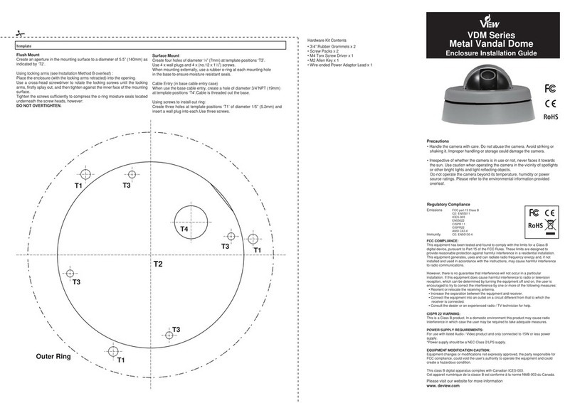
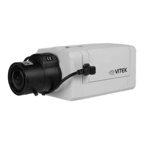
DeView CR Series User manual

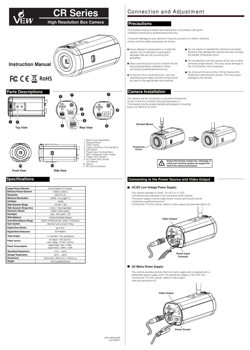
Camera Installation
The camera can be mounted by using either the bracket mount on the top or bottom (see part description 2).
The bracket mounts accept standard photographic mounting bolts (1/4" BSW or 20 UNC).
Precautions
Connecting to the Power Source and Video Output
Ensure the bracket, screws (inc. wall plugs, if
used) and mounting surface can support the
load of the camera and bracket.
Specifications
Video Output
The camera operates in either dual power (24 VAC / 12 VDC) or main power (220V).
Connections are indicated in the rear panel of the camera.
The power supply must be stable power source and should only be installed by qualified personnel.
Connect the 75 Ohm coaxial cable to video output (see part description 8).
AC/DC Low Voltage (24VAC / 12VDC)
AC Voltage (220V)
TV System
Image Sensor
Resolution
Scanning
Frequency
Effective Picture
Element
Video Output
S/N Ratio
Storage Temperature
Operating Temperature
Power Consumption
Power Source
NTSC / PAL
NTSC
PAL
976(H) x 494(V)
NTSC
PAL
NTSC
PAL
976(H) x 582(V)
60Hz
50Hz
700 TVL
1.0Vpp Composite Output
220 VAC ±10% (50/60 Hz)12 VDC ±10% / 24 VAC ±20%
Normal:2.2W Normal:2.2W
Dimensions 63mm (W) x 57mm (H) x 120.2mm(L)
-10°C ~ +50°C
-20°C ~ +60°C
2nd Video Output Yes (supports installation check)
Minimum Illumination
Auto White Balance Range
White Balance Control
Backlight Compensation (BLC)
Sync System
Privacy Zone
Motion Detection
Shutter Speed
Shutter Control
1/60 ~ 1/100000
1/50 ~ 1/100000
ATW / Manual / Push / Push Lock / USER1,2
Indoor:1800K~10500K / Outdoor:6500K~10500K
INT /LL
4 Areas
Functional Specifications
General Specifications AC/DC Dual Power Model AC Mains Power Model
Full Range
AGC Gain Control 44.8 dB
Day/Night SDN(AUTO ,COLOR ,NIGHT)
Adaptive Tone Reproduction (ATR) OFF / LOW / MID / HIGH
High-Light Compensation (HLC) ON/OFF
Up to 15 Masks
Digital Noise Reduction
Digital Zoom
DIS
3D DNR
255X Max
On/Off
Gamma Compensation 0.45
AUTO/MANUAL/FIX
Mirror OFF/V-FLIP/H-FLIP/HV-FLIP
Defog ON/OFF
Sony 1/3" Super HAD-II
V531-CR035-S00
VER. 11/2015
CCD Box Camera
Instruction Manual
www.devieweurope.com
.
Never attempt to disassemble or modify the camera.
Any modification could lead to damages that are not
covered by the guarantee.
Make sure the power source is switched off and
disconnected before installation. Refer servicing to
qualified personnel only.
Do not expose or operate the camera in wet areas.
Moisture may damage the camera and also increase
the danger of electrical shock.
Do not attempt to aim the camera at the sun or other
extremely bright objects. This may cause damage to
the CCD and the void of warranty.
Do not touch the lens or the CCD by hands while
installing or adjusting the camera.This may cause
damage to the camera.
This product must be installed and maintained in accordance with good installation practices by qualified personnel only.
To prevent damage to your camera or injury to yourself or to others, read and comply with the safety precautions as follows:
regulated power supply and the wiring should
be used for the appropriate input terminal.
To prevent fire or electrical shock, use only
700 TVL Day / Night
Color Camera
Side View
Rear View
11
1. Back Focus Adjustment
2. Bracket Mount
3. OSD Control
4. Video Lens Drive Terminal Block
5. Day/Night Switch
6. Power Input Terminal Block
(DC/AC Low Voltage)
7. BNC Composite Video Output
8. Power LED Indicator
9. AC Power Input Socket
(AC Mains)
10. CCD Sensor
11. DC Lens Connector
Top View
12
Front View
10
7
8
6
4
5
37
9
12 12
8
100~240VAC~ 50/60Hz
LAMP
LAMP
LAMP
Parts Descriptions
12. Second Video Output
Bracket Mount
Protective
Cover
GND
+12V
VIDEO
GND
D/N SW
VIDEO OUT
Power Input
Terminal
Video Output
Power Input
Terminal
POWER
VIDEO OUT
100~240VAC~ 50/60Hz
GND
+12V
VIDEO
GND
LAMP
0.3 Lux (F1.2, 50 IRE,AGC ON)
50 dB (100 IRE, F1.2)
All manuals and user guides at all-guides.com
all-guides.com

Connection and Adjustment
Lens Installation
Direct Drive (D.C.)Lens Mounting
1. If using a C-mount lens, attach the C-CS mount adaptor before installing the lens.
2. Move the back focus adjustment lever fully to the left, with the lens facing towards you
(see Back Focus Adjustment).
3. Install the lens on to the camera.
4. For Direct Drive Lens application, connect the DC Lens Connector to the side of the camera.
Fit the lens to the camera according to the following connection assignments.
5. Adjust the Back Focus to the correct position then secure the screw.
6. Adjust the Zoom and Focus levers of the lens to acquire a clear image and
the required field of view.
Video Drive Lens Mounting
1. If using a C-mount lens, attach the C-CS mount adaptor before installing the lens.
2. Move the back focus adjustment lever fully to the left with the lens facing
towards you (see Back Focus Adjustment).
3. Install the lens on to the camera.
4. For Video Drive Lens application, connect the wires to the rear panel of the
camera. Fit the lens to the camera according to the following connection
assignments.
Strip 6mm of insulation from lens wires. Depress button to open cable clamp
aperture and insert bare end into clamp. Release button to secure wire.
5. Adjust the Back Focus to the correct position then secure the screw.
6. Adjust the Zoom and Focus levers of the lens to acquire a clear
image and the required field of view
Installing the Lens
Before installing a lens, you must first
remove the protective cover from the
camera. If mounting a C-Mount lens,
attach the C-CS mount adaptor to
the camera.
Adjust the Back Focus to acquire a
sharp image (see Back Focus
Adjustment).
Back Focus Adjustment
There is a mechanism for back focus adjustment.
Loosen the back focus locking screw.
Move the adjustment lever to obtain optimum focus of
the image.
Tighten the screw to lock the back focus
adjustment lever in place. Back Focus Adjustment Lever
Video Drive Lens
Terminal
Button
Press to Open
the Clamp
Cable Clamp
Manual / Fixed Lens Mounting
1. If using a C-mount lens, attach the C-CS mount adaptor before installing the lens.
2. Move the back focus adjustment lever fully to the left, with the lens facing towards you
(see Back Focus Adjustment).
3. Install the lens on to the camera.
4. Adjust the Back Focus to the correct position then secure the screw.
5. Adjust the Zoom and Focus levers of the lens to acquire a clear image and the
required field of view.
GND
LAMP
VIDEO
+12V
GND
VIDEO LENS
Camera OSD Menu
SCENE SELECT FULL AUTO
INDOOR
OUTDOOR
BACKLIGHT
ITS
CUSTOM
AE LEVEL 001 ~ 250
6.0DB ~ 44.8DB
AUTO / OFF
256FLD ~ 1/10000
6.0DB ~ 44.8DB
256FLD ~ 1/10000
6.0DB ~ 44.8DB
AGC MAX
SENS UP
SHUTTER
AGC MAX
WHITE BAL
SHUTTER /
AGC
MANUAL
HLC/BLC OFF
HLC CLIP LEVEL
ATW
(*1)
PUSH
USER1
SPEED
DELAY CNT
ATW FRAME
ENVIRONMENT
RGAIN
PAGE1
AUTO
SHUTTER
AGC MAX
FIX
ANTI CR AUTO/OFF/ON
ON/OFF
DIS
PICT ADJUST
SHARPNESS
HUE
COLOR GAIN
BRIGHTNESS
CONTRAST
EXIT
SYS SETTING
ON POS
SYNC MODE
LENS
COMMNUNICATION
CAMERA ID OFF
INT/LL(*6)
MANUAL
AUTO
FLIP OFF/V/H/VH
LCD/CRT
TYPE
MODE
ADJUST
SPEED
ADDRESS
PROTOCOL
BAUDRATE
DATABIT
PARITY
STOPBIT
000 ~ 255
001∼255
001∼255
000 ~ 255
INDOOR / SUNNY / SHADE / AUTO
000 ~ 255
DAY/NIGHT DAY
NIGHT
BURST
BURST ON/OFF
ON/OFF
INT/EXT1/EXT2CNTL SIGNAL
DELAY CNT
DAY->NIGHT
NIGHT->DAY
AUTO
LENS SHD COMP
SET1 / SET2 / SET3
000 ~ 959
PATTERN
POSH
POSV
OFF
ON
000~490
DEFOG(*5)
LEVEL LOW / MID / HIGH
OFF
ON
EZOOM OFF
ON MAG/PAN/TILT
PRIVACY MASK AREA SEL 1~15
DISPLAY
POSITION
COLOR
TRANSP
MOSAIC
OFF / ON
WHITE / BLACK / RED /GREEN / BLUE /
YELLOW / CYAN / MAGENTA
0.00 / 0.50 / 0.75 / 1.00
OFF / ON
PAGE2
LANGUAGE
VERSION
MAINTENANCE
EXIT
ENGLISH/中文/ESPANOL/PORTUGUES/PYCCKNN/FRANCAIS/DEUTSCH/日本語
W.PIX MASK
SAVE
NOT SAVE
CANCEL
BACK
MANUAL REGISTRATION
REG.POINT
CURSOR COLOR
BLINK
REG.NUMBER
AUTO
DATA CLEAR
RUN
BACK
CAMERA RESET
IR OPTIMZER OFF
ON MODE AUTO
CENTER
TOP
BOTTOM
IR AREA
LEVEL
﹍﹍﹍﹍﹍﹍
0-12
0~ 6
0~ 6
0~ 8
0~ 8
00~ 15
000 ~ 255
IR LED
FIX
DAY/NIGHT LEVEL MIN
LEVEL
LEVEL MAX
OFF
ON COLOR GAIN
PATTERN
POSH
POSV
LEVEL
COLOR NIGHT
IR SHADE COMP
OFF
001 ~ 255
001 ~ 255
LOW / MID / HIGH
SET1 / SET2 / SET3
000 ~ 959
000~490
OFF / LOW / MID / HIGH
OFF
ON
LEFT
RIGHT
WEIGHT
FLK LESS
MODE GAIN CNTL
SHUTTER FIX
MODE GAIN CNTL
SHUTTER FIX
ON
OFF
AUTO
MOTION DET OFF DETECT SENSE
INTERVAL
BLOCK DISP
MASK AREA
MOTION AREA MODE
AREA SEL
TOP
BOTTOM
LEFT
RIGHT
ON
1~4
BGAIN
USER2 RGAIN
MANUAL
PUSH LOCK
000 ~ 255
000 ~ 255
00 ~ 63
000 ~ 255
BLC(*2)
ATR-EX(*3)
LOW / MID / HIGH(*4)
LOW / MID / HIGH / OFF
DNR LEVEL 0 ~ 6
BGAIN
LEVEL
OFF
ATR-EX CONTRAST
CLEAR FACE
This can not be changed except CUSTOM mode.
Protective
Cover
Back Focus
Adjustment Lever
Lens
(Not Supplied)
C-CS Mount Adaptor
(for C-type Lens)
Zoom and Focus
Adjustment Levers
Back Focus
Adjustment Lever
Lens
(Not Supplied)
Zoom and Focus
Adjustment Levers
DC Lens
Pin Assignments
Lens
Connector
Pin Number DC Drive
Pin 1 Damp-
Pin 2 Damp +
Pin 3 Drive +
Pin 4 Drive -
2
1
4
3
Back Focus
Adjustment Lever
Lens
(Not Supplied)
Zoom and Focus
Adjustment Levers
Back Focus
Adjustment Lever
Lens
(Not Supplied)
Zoom and Focus
Adjustment Levers
Camera Setup
All manuals and user guides at all-guides.com
Other DeView Security Camera manuals
DeView
DeView Tamper Proof User manual
DeView
DeView CQ Series User manual
DeView
DeView BTP12H37V12L User manual

DeView
DeView CR Series User manual
DeView
DeView MD3CN12M User manual
DeView
DeView CCD User manual
DeView
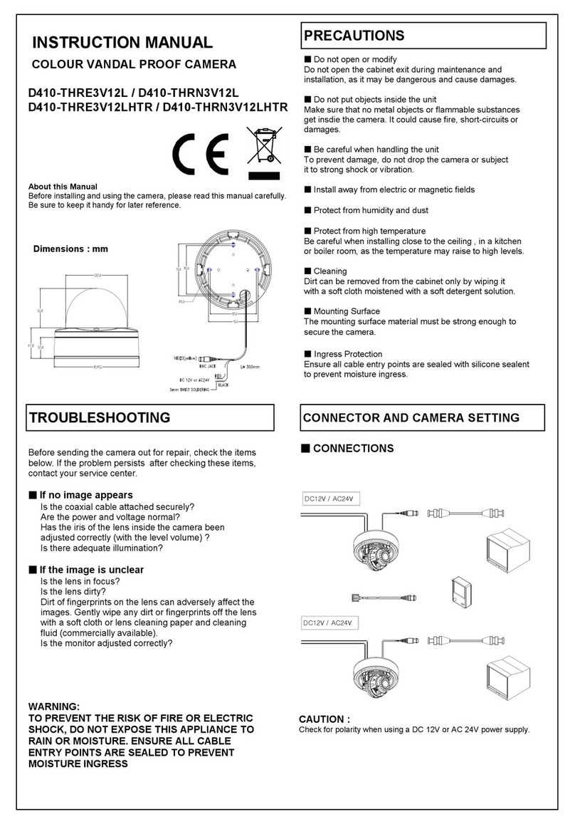
DeView D410-THRE3V12L User manual
DeView
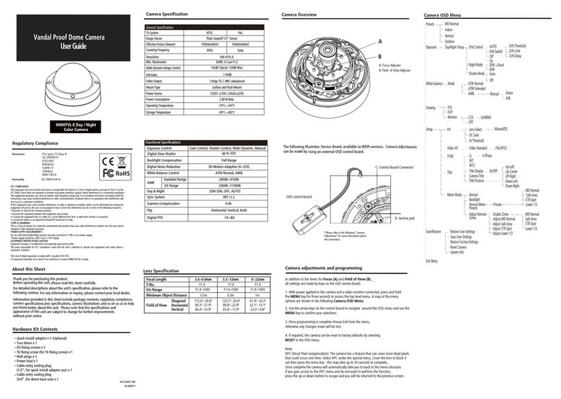
DeView 690HTVL-E User manual
DeView
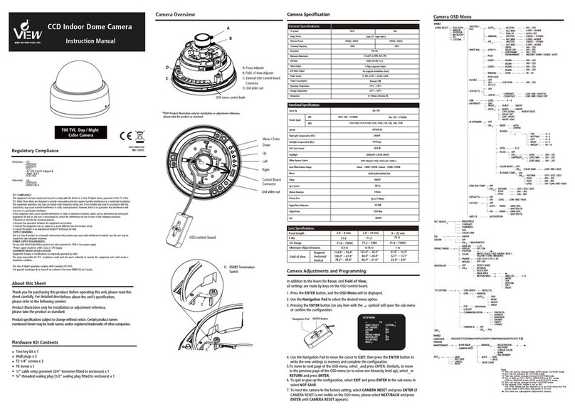
DeView MD4SP70 User manual
DeView
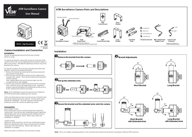
DeView ATMP7W User manual
Popular Security Camera manuals by other brands
SECO-LARM
SECO-LARM Enforcer EV-5120-N3WQ manual
RoadHawk
RoadHawk 1080P High Performance Forward Facing Camera user manual
Vitek
Vitek VTC-C2BMS2 manual
Mobotix
Mobotix M25 Allround B036 manual
Conceptronic
Conceptronic DARAY01W Multi Language Quick Guide
VADDIO
VADDIO PowerVIEW HD-22 Installation and user guide
