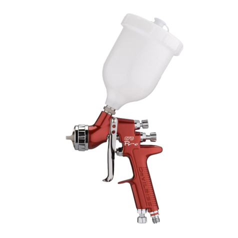
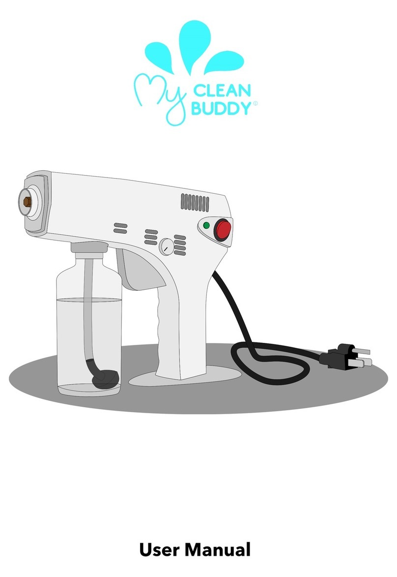
DeVilbiss SRi User manual
Other DeVilbiss Paint Sprayer manuals

DeVilbiss
DeVilbiss JGA-635G Reference manual

DeVilbiss
DeVilbiss Compact MINI Service manual

DeVilbiss
DeVilbiss Pro Lite E User manual

DeVilbiss
DeVilbiss AGX-550 User manual
DeVilbiss
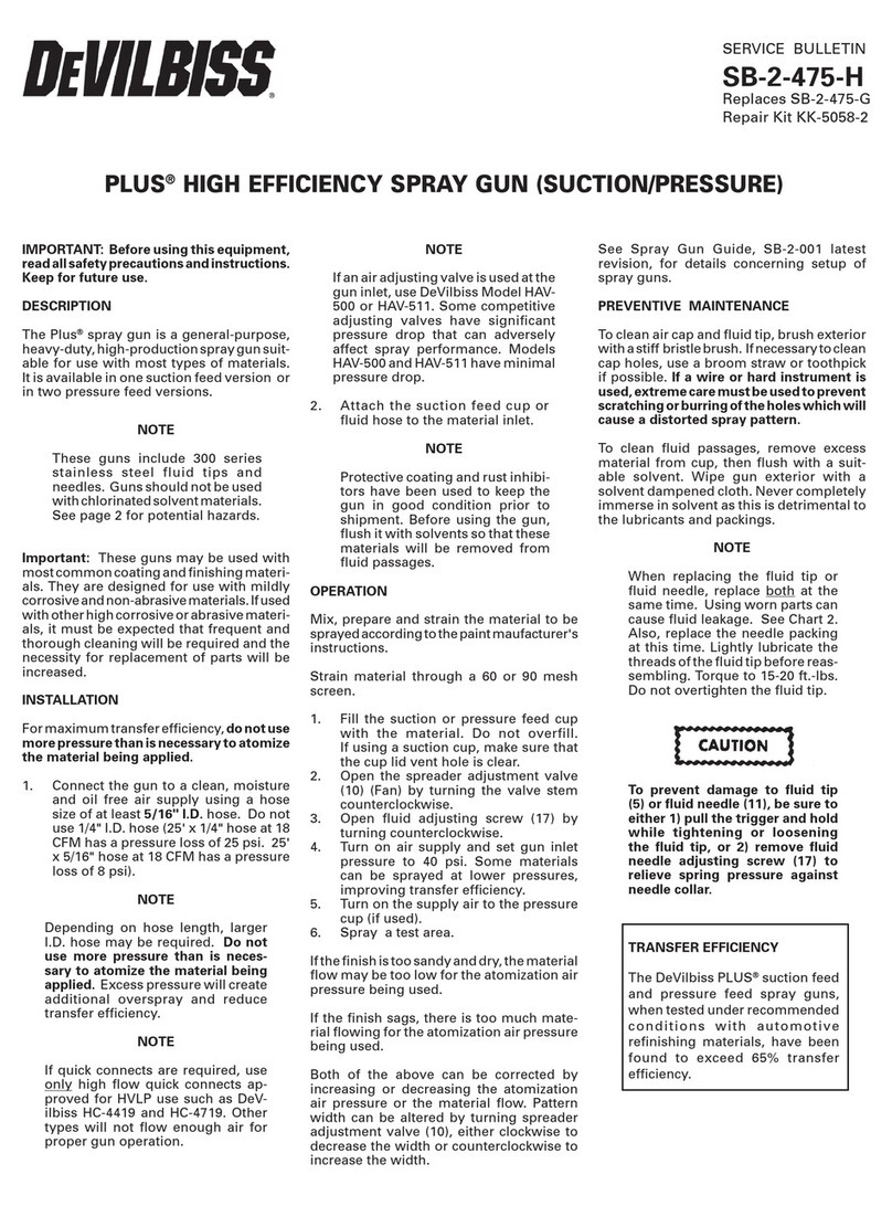
DeVilbiss Plus SB-2-475-H Reference manual
DeVilbiss
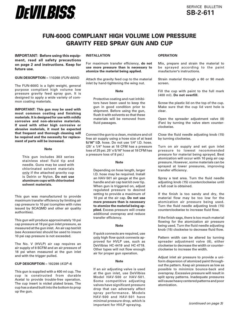
DeVilbiss FUN-600G Reference manual
DeVilbiss
DeVilbiss COMPACT COM-G430-16 User manual

DeVilbiss
DeVilbiss SGK-600-PR Operating instructions

DeVilbiss
DeVilbiss GTIPRO LITE Service manual
DeVilbiss
DeVilbiss FinishLine TGC-500-2 User manual

DeVilbiss
DeVilbiss PRI Pro Lite User manual

DeVilbiss
DeVilbiss JGA Operating instructions

DeVilbiss
DeVilbiss SGA-570 User manual
DeVilbiss
DeVilbiss JGA-510-DEC Reference manual

DeVilbiss
DeVilbiss SB-21-058-H User manual
DeVilbiss
DeVilbiss FLG-G5-14 User manual
DeVilbiss
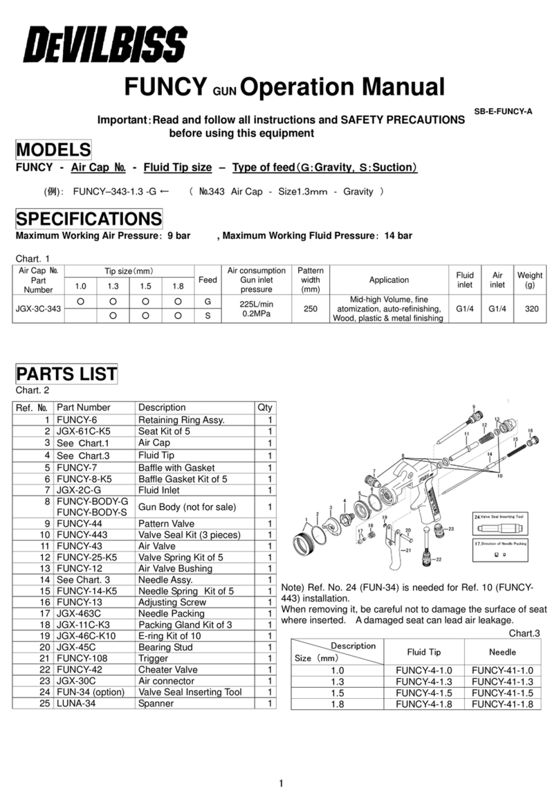
DeVilbiss FUNCY JGX-3C-343 User manual
DeVilbiss
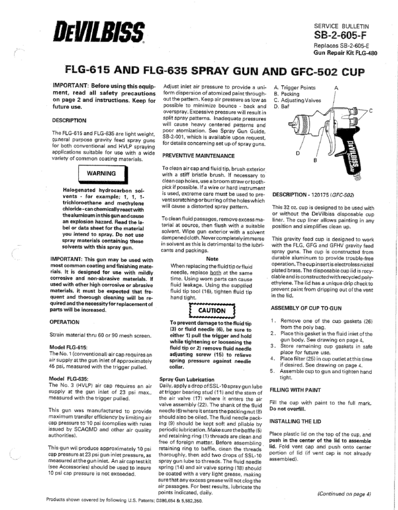
DeVilbiss FLG-615 User manual

DeVilbiss
DeVilbiss MSA-510-DEC Reference manual

DeVilbiss
DeVilbiss FLG-692 User manual
Popular Paint Sprayer manuals by other brands

zogics
zogics Z-DAS instruction manual

KISANKRAFT
KISANKRAFT KK-KBS-165 Operation manual

Matrix
Matrix SG 650 Translation of the original instructions

Anest Iwata
Anest Iwata SGA-3 Installation, use & maintenance instruction manual

paasche
paasche VV Instructions and parts list

Carlisle
Carlisle DeVilbiss JGA-510 Service manual

