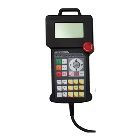
WEIHONG PM53B User manual

PM53B/53C CNC System
Manufacturers’ Manual
7th Edition
Weihong Electronic Technology Co., Ltd.

The copyright of this manual belongs to Weihong Electronic Technology Co., Ltd. (hereinafter referred to as
Weihong Company). This manual and any image, table, data or other information contained in this manual may
not be reproduced, transferred, or translated without any prior written permission of Weihong Company.
The information contained in this manual is constantly being updated. You can login to the official website of
Weihong Company www.en.weihong.com.cn to download the latest PDF edition for free.

Specialized Concentrated Focused
Preface「I」
Preface
About This manual
This manual is intended for manufacturers. If you use the CNC system for the first time, you need to
read through the manual. If you are experienced with the system, you can search for the desired info
via the contents.
With 5 chapters, this manual can be divided into 4 parts, as follows:
1) Part 1: preface, introducing the precautions about transportation and storage, installation, wiring,
debugging, usage, and so on. You need to read them carefully beforehand to ensure safe
operations.
2) Part 2: product, including chapter 1. It consists of product overview including system configuration
and introduction to interfaces.
3) Part 3: operation and application, including chapter 2, 3 and 4, which introduces wiring instruction,
wiring, and machine tool debugging respectively.
4) Part 4: appendix, including chapter 5, which states the software license agreement.
Applicable Product Models
This manual is applicable to PM53B/53C control card. Refer to the table below for details:
Product Model
Remarks
PM53B/53C Control Card
Self-developed high-performance motion control card, it can be
connected with stepping or servo driver with 3 channels, for supporting
three axes synchronized motion. It adopts position control method and
differential signal control. Pulse frequency is 160KHZ. The system
boasts of protective mechanism and is a proven stable control system.
Contact Us
You can contact us by the following info for technical support and pre-sales/after-sales service:
Company Name: Weihong Electronic Technology Co., Ltd.
Headquarters Address: No.1590, Huhang Rd., Fengxian, Shanghai, PRC 201400
Tel: +86-21-33587550
Fax: +86-21-33587519
Website: http://en.weihong.com.cn

Specialized Concentrated Focused
「II」Preface
Revision History
You can refer to the following table for the revision records of each edition.
Date
Edition
Revision Contents
2016.02
R7
1) Contact information updated.
2016.01
R6
1) Wiring diagram updated in section 3.3, 3.4 and 3.5.
2) Detailed debugging step 2 and 5 updated in section 4.1.
3) Document style updated.
2015.08
R5
Including:
1) Manual hardware driver update in section 2.2;
2) Update MPG interfaces definition in section 3.2 ;
3) Update the wirings of terminals in section 3.4;
4) Machine debugging steps update in section 4 .
Precautions
Precautions can be divided into caution and warning according to the degree of possible loss or injury
in case of negligence or omission of precautions stipulated in this manual.
CAUTION
: general info, mainly for informing, such as supplementary instructions and
conditions to enable a function. In case of negligence or omission of this kind of precautions, you may
not activate a function. Note that in some circumstances, negligence or omission of even this kind of
precautions could cause physical injury or machine damage.
WARNING
: warning info requiring special attention. In case of negligence or omission of
this kind of precautions, you may suffer physical injury, or even death, machine damage or other
losses.
WARNING
1) Precautions Related to Storage and Transportation
The products should be transported properly in terms of the weight;
An excess of specified quantity of stacking products is prohibited;
Climbing, standing or placing heavy loads on the products is prohibited;
Dragging or carrying the products via cables or devices connected to them is prohibited;

Specialized Concentrated Focused
Preface「III」
WARNING
2) Precautions Related to Installation
Only when this equipment installed in the qualified electricity cabinet can it be used. The
construction of the cabinet must reach IP54 grade of protection;
Paste sealing strips on the joint of the cabinet to seal all the cracks;
Cable entry should be sealed while easy-to-open on the spot;
A fan or heat exchanger should be adopted for the heat dissipation and air convection of the
cabinet;
If a fan is adopted, air strainer is a must in air inlet or air outlet;
Dust or cutting fluids may have access to the CNC device via the tiny cracks and tuyere.
Therefore it is necessary to pay attention to the surroundings and air flow direction of the air
vent to make sure that the outflow gas is towards pollution source;
100 mm space should be preserved between the back of the CNC device and the cabinet wall
for plugging cable connected with the device and the ventilation & heat dissipation in the
cabinet;
Space between this device and other equipments should also be preserved according to the
requirements;
The product should be installed firmly and without vibration. During installing, casting,
knocking, striking, or loading on the product is forbidden;
To reduce electromagnetic interference, power-supply components used should be above AC
or DC 50V and the space between cable and CNC device should be preserved above 100mm;
It will be better if CNC device is installed at a position facilitating debugging and maintenance.
3) Precautions Related to Wiring
Only qualified people are allowed to participate in the wiring and checking;
The CNC device should be grounded reliably and grounding resistance should be less than 4
ohm. Neutral line is absolutely not allowed to replace earth wire. Otherwise, it may result in
malfunction of the device due to the interference;
Wiring should be firm and steady, or misoperation may occur;
Voltage values and positive & negative polarity of any connection plug should be in accordance
with specifications set forth in the manual, or it may result in breakdowns such as short circuit
and permanent damage to the device;
To guard against electric shock or CNC device damage, fingers should keep dry before
plugging or touching switch;
The connecting wire should not be damaged and squeezed, or the leakage or short circuit may
occur;

Specialized Concentrated Focused
「IV」Preface
WARNING
It is prohibited to plug or open the chassis of CNC device when power on.
4) Precautions Related to Running & Debugging
Parameters setting should be checked before running, since wrong setting may lead to
accidental movements;
Modification to parameters should be within the allowable range, or such breakdowns as
unsteady running and machine damage will occur.
5) Precautions in Use
Before power-on, please make sure that the switch is on blackout to avoid occasional start-up;
Please check the electromagnetic compatibility during electrical design in order to avoid or
reduce electromagnetic interference to the CNC device. A low pass filter should be employed
to reduce electromagnetic interference if there are other electrical devices nearby;
It is not allowed to frequently power on and power off. It is recommended to power up the
machine again at least one (1) minute later after power failure or blackout.
CAUTION
1) Precautions Related to Product and Manual
Matters related to restrictions and functions available stipulated in the manuals issued by the
machine manufacturer are prior to those in this manual;
This manual assumes all the optional functions are available, which you must confirm through
manuals issued by the machine manufacturer;
Please refer to manuals issued by the machine manufacturer for the instructions of machine
tools;
Functions, and software interfaces vary with the system and the version of software. Before
using the system, you must confirm the specifications.
2) Precautions When Opening the Package
Please make sure that the products are what you have ordered;
Check if the products are damaged in transit;
Check if the components and accessories are damaged or missing in terms of the detailed list;
Please contact us promptly if product discrepancy, accessory missing or transit damage
occurs.

Specialized Concentrated Focused
Preface「V」

Specialized Concentrated Focused
「VI」Contents
Contents
1Overview ........................................................................................................................1
2Installation......................................................................................................................2
2.1 Installation Steps.......................................................................................................................... 2
2.2 Manually Update the Hardware Driver........................................................................................ 2
2.3 Customized Installation Package................................................................................................ 5
3Wiring .............................................................................................................................6
3.1 Signal Types.................................................................................................................................. 6
3.1.1 Binary Input Signal..................................................................................................................................... 6
3.1.2 Relay Output Signal.................................................................................................................................... 6
3.1.3 Differential Output Signal .......................................................................................................................... 7
3.2 MPG Interfaces.............................................................................................................................. 7
3.3 Wiring Diagram of Terminal Board ............................................................................................. 9
3.4 Wiring Diagram of Terminal Board and Stepping Driver........................................................ 12
3.4.1 Connection to Stepping Driver with COM Port........................................................................................ 12
3.4.2 Connection to Differential Input Stepping Driver .................................................................................... 12
3.5 Wiring Diagram of Terminal Board and Servo Driver ............................................................. 13
3.5.1 Wiring with WISE Servo Driver ................................................................................................................ 13
3.5.2 Wiring with YASKAWA Σ-ⅡServo Driver................................................................................................ 13
3.5.3 Wiring Diagram of DELTA ASDA_ A/AB Servo Driver................................................................................ 14
3.5.4 Wiring Diagram of PANASONIC MINAS_A5 Servo Driver......................................................................... 15
3.5.5 Wiring Diagram of MITSUBISHI MR-E Servo Driver ................................................................................. 15
3.5.6 Wiring Diagram of FUJI FALDIC-β Servo Driver ........................................................................................ 16
3.5.7 Wiring Diagram of STONE GS Servo Driver.............................................................................................. 16
3.6 Parameter Setting of Servo Drivers.......................................................................................... 17
3.6.1 Parameter Setting of WISE Servo Driver.................................................................................................. 17
3.6.2 Parameter Setting of YASKAWA Σ-ⅡServo Driver.................................................................................. 18
3.6.3 Parameter Setting of DELTA ASDA_ A Servo Driver.................................................................................. 19

Specialized Concentrated Focused
Contents「VII」
3.6.4 Parameter Setting of DELTA ASDA_B Servo Driver................................................................................... 20
3.6.5 Parameter Setting of PANASONIC MINAS_A4 Servo Driver ..................................................................... 21
3.6.6 Parameter Setting of MITSUBISHI MR-E Servo Driver.............................................................................. 21
3.6.7 Parameter Setting of FUJI FALDIC-β Servo Driver .................................................................................... 22
3.6.8 Parameter Setting of STONE GS Servo Driver .......................................................................................... 23
4Machine Tool Debugging...............................................................................................25
4.1 Debugging Steps ........................................................................................................................ 25
4.2 Pulse Test.................................................................................................................................... 30
5Software License Agreement.........................................................................................31


Specialized Concentrated Focused
Overview「1」
1 Overview
PM53B control system consists of following components:
1) One motion control card of PM53B
2) One CD of NcStudio motion control software (not required if the software is customized)
3) One terminal board of EX23A
4) One DB37M/F cable (3m)
5) One FC16-DB15F cable (with rail block) for Manual Pulse Generator (MPG)
6) NK-MPG-05 (Optional)
PM53C control system consists of following components:
1) One motion control card of PM53C
2) One CD of NcStudio motion control software (not required if the software is customized)
3) One terminal board of EX23A
4) One DB37M/F cable (3m)
D1 PM53B/53C Motion Control Card
JP1
DB37M
JP2
Gold Fingers
Fig. 1-1 Structural Drawing of PM53B/53C Motion Control Card
See Fig. 1-1. PM53B/53C Motion Control Card uses PCI interface.
The size of PM53B control card is 165mm* 120mm. The Control Card has 2 sockets: JP1 is the
DB37M socket for the connection of control signals, and connected to the EX23A terminal board with
the cable DB37M/F. JP2 is the socket for Manual Pulse Generator (MPG) and connected to the back of
the host computer with the cable FC16-DB15F (with rail block).
The size of PM53C control card is 156mm* 96mm, with only one socket, JP1, which is DB37M socket
for the connection of control signals, and connected to the EX23A terminal board with cable DB37M/F.
CAUTION
There is a red LED D1 on each motion control card, which indicates their work status. When NcStudio runs
normally, D1 is off or it glows.

Specialized Concentrated Focused
「2」Installation
2 Installation
2.1 Installation Steps
1) Insert the software NcStudio CD to the CD driver of computer, and then double click the icon
for installation of the software;
2) Power off the computer, then open the chassis of host computer, then insert the control card to a
PCI slot and then fasten the rail block screw (if there is an extended flat cable, its rail block should
also be fixed), and then well cover the host computer chassis;
3) Power on the computer. The computer will find the new hardware-device and install its driver
automatically;
4) Double click the shortcut icon of NcStudio on the desktop; if it runs normally, installation is over. (If
the control system runs abnormally, please check whether the control card is well inserted and
whether the gold finger is clean)
2.2 Manually Update the Hardware Driver
1) Right click “My Computer”, select “Properties”, and then click “Device Manager”. Choose the
“CNC Adaptor”item, right click on it and select “Update Driver Software…” Users can begin
updating process according to the wizard. Adialog box as Fig. 2-1 will pop up.
Fig. 2-1 Hardware update wizard
2) Select “Install form a list of specific location (Advanced)”, click [Next] to continue. A dialog box as
Fig. 2-2 will pop up.

Specialized Concentrated Focused
Installation「3」
Fig. 2-2 Choose search and installation option
3) Select “Don‟t search, I will choose the driver to install”, click [Next] to continue. A dialog box
containing compatible hardware will pop up, as shown in Fig. 2-3,
Fig. 2-3 Select the driver manually
4) Click [Have Disk...] button to open the next dialog box. A dialog box named “Install From Disk” will
pop up, as shown in Fig. 2-4.
Fig. 2-4 Select the target file of driver
5) Click “Browse”to open a dialog box named “Locate File”, as shown in Fig. 2-5, select the target
hardware driver in the list. Choose the target file “NcadptPci(PCIMC-6A).inf”under the directory of
C:\ProgramFiles\Naiky\PCIMC-6A.

Specialized Concentrated Focused
「4」Installation
Fig. 2-5 Select the hardware driver
6) After hardware driver being correctly chosen, the interface jumps to the previous dialog box where
the target file directory will be displayed under item “Copy manufacturer‟s files from:”, as shown in
Fig. 2-6.
Fig. 2-6 Target file directory confirmation
7) Click [OK] to go back, and then click [Next] to start updating the driver software. The progressing
picture is shown as Fig. 2-7.
Fig. 2-7 Updating the driver
8) When the updating is finished, a dialog as shown in Fig. 2-8 will pop up. Click [Finish] to complete
the update of the hardware driver.

Specialized Concentrated Focused
Installation「5」
Fig. 2-8 Driver update completed
2.3 Customized Installation Package
A tool, named NcHelper.exe under the installation directory, helps customize setup installation
package. For example, when you want to change the settings of some parameters and set them to
default value in the process of using NcStudio, to achieve the best performance of a machine tool, you
can change the settings, find this tool, double click it, select a default configuration, and generate a
new software package with the parameter settings changed.

Specialized Concentrated Focused
「6」Wiring
3 Wiring
3.1 Signal Types
3.1.1 Binary Input Signal
Binary input signal is active low; it supports NO (Normally Open) and NC (Normally Closed) input
signals (by modifying the polarity of input ports in the software). When using a NO switch, the signal is
available as connecting with COM; when using a NC switch, the signal is available as disconnecting
with COM.
When the mechanical switch connects with binary input signal, one end of the mechanical switch
connects to the binary input port and the other end to GND, as shown in Fig. 3-1:
GND
IN
24V
I/O Board Card
Fig. 3-1 Connection between Mechanical Switch and Binary Input Signal
The binary input signal can also be connected with a photoelectric switch or proximity switch of NPN
(NO) or NPN (NC) type. The connection diagram is shown below in Fig. 3-2:
24V
COM
IN
24V
I/O Board Card External Input
Recommended
10K
Fig. 3-2 Connection between Binary Input Signal and Photoelectric Switch (or Proximity Switch)
3.1.2 Relay Output Signal
The relay output contact points on the terminal board have load capacity: 10A/250VAC and

Specialized Concentrated Focused
Wiring「7」
10A/30VDC, which can control 220V AC load of low power. If high power load is needed, a contactor
can be used. See Fig. 3-3 for the connection.
AC
Machine Tool
(for reference)
CON
COM
N.C
N.O
Terminal Board
Output
Control
Fig. 3-3 Connection between Contactor and Relay Output
3.1.3 Differential Output Signal
Pulse command form: pulse plus direction, negative logic. The maximum pulse frequency: 160KHZ.
The sketch map of pulse mode is shown below in Fig. 3-4:
PUL+
DIR+
FWD REV
‘L’
1 2 3 12 3
‘H’
Fig. 3-4 Type of Pulse Command Output
Output mode of differential signal is shown as below in Fig. 3-5:
VCC
XP-
XP+
XP
Fig. 3-5 Output Circuit of Pulse Command
3.2 MPG Interfaces
JP2 interface on PM53B motion control card is used for connection with handwheel, or MPG, via a
FC16-DB15F connector. Please note that handwheel is an optional component, and the pins definition
for interfaces of handwheel developed by Weihong Company is illustrated as below:

Specialized Concentrated Focused
「8」Wiring
9: HSU
10: HSA
11: GND
12: HSB
13: HSZ
14: HSY
15: HSX
7:HX10
6:HX1
5:NC
4:NC
3:HB
2:HA
1:+5V
8:HX100
Fig. 3-6 Pins definition of MPG interfaces
See table 1 for specific pin definition of the MPG interfaces.
Table 1 pin definition of the MPG interfaces
Pins No.
Definition
Description
1
+5V
Power on handwheel
2
HA
Encoder phase A signal
3
HB
Encoder phase B signal
4
NC
-
5
NC
-
6
HX1
X1 override
7
HX10
X10 override
8
HX100
X100 override
9
HSU
Selection of the fourth axis
10
HSA
Selection of the fifth axis
11
GND
Digital ground
12
HSB
Selection of the sixth axis
13
HSZ
Selection of Z axis
14
HSY
Selection of Y axis
15
HSX
Selection of X axis

Specialized Concentrated Focused
Wiring「9」
3.3 Wiring Diagram of Terminal Board
Terminal Board EX23A
See Fig. 3-7 for the wiring diagram of the terminal board EX23A (154mm*72mm), for standard XYZ
axes configuration for engraving machines.
SVC
GND
SPIN
Output
Relay
Area
DB37 Socket
POWER
AVI
ACM
+
SPCOOL
Y-0
Z-0
COM
X-0
ZD-
ZD+
ZP-
ZP+
+5V
X-axis Driver Interface
COM
START
CUT
STOP
ESTOP
Power Status Indicator
OIL
GREEN
RED
YD-
YD+
YP-
YP+
+5V
Y-axis Driver Interface
Y-axis Driver
XD-
XD+
XP-
XP+
+5V
Z-axis Driver Interface
X-axis Driver
Operation Inputs
GND
Cycle Stop
Cycle Start
Tool Sensor Signal
E-stop
Home Inputs
GND
Home (Y)
Home (X)
Analog
Output
Analog Voltage
Analog GND
24VDC
Power Input
PM53B/53C Motion Control Card
Spindle ON
Auto Lube
Green
Red
Home (Z)
EX23A3
COM
+24V
-
Z-axis Driver
Fig. 3-7 Wiring Diagram of Terminal Board EX23A

Specialized Concentrated Focused
「10」Wiring
Terminal Board 6B-EX4A
See Fig. 3-8 for the wiring diagram of the terminal board 6B-EX4A (295mm*76mm).
SVC
GND2
SPIN
Output
Relay
Area
DB37 Socket
COM
AVI
ACM
FOR
DCM
+-
DC
DC
COOL
Y-0
Z-0
COM
X-0
Z1D+
Z1D-
Z1P+
Z1P-
Z-axis Driver
OIL
GREEN
RED
Workpiece
Cool
Oil Pump
Green Light
Red Light
Z1-axis Driver
Interface
Home Inputs
GND
Home (Z)
Home (Y)
Home (X)
Red
Green
Oil
Workpiece
Cool
Spindle
ON
Analog Voltage
Analog GND
Forward
Rotation
Digital GND
24V Power
Input
PM53B/53C Motion Control Card
GND
ESTOP
Cycle Stop
Cycle Start
Tool Sensor Signal
E-stop
Z2D+
Z2D-
Z2P+
Z2P-
Z2-axis Driver
Interface
Z3D+
Z3D-
Z3P+
Z3P-
Z3-axis Driver
Interface
Z4D+
Z4D-
Z4P+
Z4P-
Z4-axis Driver
Interface
Y1D+
Y1D-
Y1P+
Y1P-
Y1-axis Driver
Interface
Y2D+
Y2D-
Y2P+
Y2P-
Y2-axis Driver
Interface
X1D+
X1D-
X1P+
X1P-
X1-axis Driver
Interface
X2D+
X2D-
X2P+
X2P-
X2-axis Driver
Interface
X3D+
X3D-
X3P+
X3P-
X3-axis Driver
Interface
X4D+
X4D-
X4P+
X4P-
X4-axis Driver
Interface
+5V
+5V
GND
GND
Power
Output
CUT
START
STOP
COM
Y-axis Driver X-axis Driver
6B-E X 4 A
+- +24V
Fig. 3-8 Wiring Diagram of Terminal Board 6B-EX4A
This manual suits for next models
1
Table of contents
Other WEIHONG Control System manuals

WEIHONG
WEIHONG NcEditor V12 User manual

WEIHONG
WEIHONG 200 Series User manual

WEIHONG
WEIHONG LS1500 User manual

WEIHONG
WEIHONG NK280B User manual

WEIHONG
WEIHONG NK280 User manual

WEIHONG
WEIHONG NK200 User manual

WEIHONG
WEIHONG NK105 G2F User manual

WEIHONG
WEIHONG NC65C User manual

WEIHONG
WEIHONG NK105 User manual

WEIHONG
WEIHONG NK300CX User manual
Popular Control System manuals by other brands

Doosan
Doosan DVF Series Operation user's manual

Panamax
Panamax M4000-PRO instructions

OPW
OPW Petro Vend 100 Installation, operation and maintenance guide

Carefree of Colorado
Carefree of Colorado BT12 Installation

Thermo Scientific
Thermo Scientific CC58114PC Installation and operation manual

Leviton
Leviton DOS05 user manual