btsr SMART 200 TTS User manual

SMART 200 TTS & IS3W/TTS
YARN CONTROL SYSTEM
Operating Manual
Rev. 2.0 – August 2003 ENGLISH

SMART 200 TTS – Rev. 2.0 – August 2003
Copyright 2003 - BTSR – All rights reserved.
This manual is intended for the users of the SMART 200 TTS system. It is suggested to carefully read the
instructions described in this manual before making the connections and use the system.
BTSR reserves the right to change in any time the contents of this manual, without notice.
For any technical or commercial problem, please contact your local BTSR dealer or call directly BTSR
customer service centre. We will be glad to meet your needs.
Thank you for your trust and good job.
The product described herein is compliant with the requirements of 89/336/EEC EMC Directive and
73/23/EEC Low Voltage Directive.
All BTSR products are covered by patents and adopt exclusive, profitable and high tech. Solutions.
BTSR® is a registered trademark “Best Technology Study & Research” of BTSR International S.p.A.
Lycra® is a trademark byDuPont

Table of Contents
SMART 200 TTS - i -
TABLE OF CONTENTS
TABLE OF CONTENTSTABLE OF CONTENTS
TABLE OF CONTENTS
INTRO
INTROINTRO
INTROD
DD
DUCTION
UCTIONUCTION
UCTION
How to use this manual.............................................................................................................................................. I.1
Symbols used .............................................................................................................................................................. I.1
Chapter 1
Chapter 1Chapter 1
Chapter 1 -
--
- OVERVIEW
OVERVIEWOVERVIEW
OVERVIEW
System components ....................................................................................................................................................1.1
System’s Operation Principles ..................................................................................................................................1.1
Special Features of SMART 200 TTS system ..........................................................................................................1.1
General Features of SMART systems ......................................................................................................................1.2
Cha
ChaCha
Chapter 2
pter 2pter 2
pter 2 –
––
–TECHNICAL DATA AND INSTALLATION
TECHNICAL DATA AND INSTALLATIONTECHNICAL DATA AND INSTALLATION
TECHNICAL DATA AND INSTALLATION
Technical Features .....................................................................................................................................................2.1
Installation ..................................................................................................................................................................2.1
Interface Connectors on SMART 200 TTS..........................................................................................................2.2
Example of Generic Application Connection.......................................................................................................2.3
Connection Cables and Power Supply Devices....................................................................................................2.4
Chapter 3
Chapter 3Chapter 3
Chapter 3 –
––
– OPERATION
OPERATIONOPERATION
OPERATION
SMART 200 TTS Terminal Features .......................................................................................................................3.1
IS3W/TTS Sensor Features .......................................................................................................................................3.4
Function of the IS3W/TTS Sensors ..........................................................................................................................3.4
Technical Characteristics of IS3W/TTS Sensor ......................................................................................................3.5
Detection area and mechanical layout (mm).......................................................................................................3.5
Connection cables...................................................................................................................................................3.5
Installation of IS3W/TTS sensors using multi-connector cable .........................................................................3.5
Installation of IS3W/TTS sensors with built-in cable .........................................................................................3.6
Sensor - Operator and Sensor - System Interfaces..................................................................................................3.6
Sensor - Operator.......................................................................................................................................................3.6
Touch Light Function ............................................................................................................................................3.7
Interpretation of the signalling lights located on the sensors .............................................................................3.7
Sensor - System...........................................................................................................................................................3.8
Electrical Characteristics of STOP Signal ...........................................................................................................3.9
Parameters that affect the sensor detection features ............................................................................................3.10
Preliminary operations for using the SMART 200 TTS terminal .......................................................................3.12
Operating Sequences................................................................................................................................................3.13
Enabling the SETUP Menu Functions (CONFIG)................................................................................................3.14
Enabling the SETUP Menu Functions (NEW, MODIFY, ERASE).....................................................................3.15
Enabling the WORK Menu Functions ...................................................................................................................3.16
Enabling the GRAPH Menu Functions..................................................................................................................3.16
CONTROL Function ...............................................................................................................................................3.17
DEVICE Parameters setting for Initial installation..............................................................................3.18
TT-TB Configuration of Sensor Working Mode: Twisting Profile (TT) or Balloon (TB) .............3.19

Table of Contents
- ii - SMART 200 TTS
TP-Ims Configuration of Winding measurement unit: Twisting per Second/Meter/Inch..............3.20
MO-CTR Configuration of System Operation in either MONITOR mode or CONTROL mode.....3.21
RES-MA Configuration of Sensor Reset Mode: Automatic/Manual...................................................3.23
lk-ULK Enabling/Disabling the Touch Light button operation ........................................................3.24
ST-NCO Configuring the level of STOP signal as Normally Closed or Normally Open ..................3.25
ST-CP Configuration of STOP Output as: Continuous or Pulse signal..........................................3.26
D_CNTR Configuration of Sensor delay time before entering the Control status .............................3.27
K FACT Configuration of Correction Factor for Twisting Computation .........................................3.28
KEYCODE Password to access SETUP and WORK menus....................................................................3.29
CLOCK Reading/Setting the Printer Clock-Calendar (rtc)................................................................3.30
SENSOR TEST Sensors Test..............................................................................................................................3.31
COM TEST Testing the Efficiency Rate over the Communications Line between the
SMART 200 TTS Terminal and Sensors...............................................................................3.32
VERS UPG Test of software version and Sensor’s version Updating .....................................................3.33
NEW Creating a New Article............................................................................................................3.34
SPEED - Creating a New Article - Machine collection speed ..............................................3.36
TPXmax -Creating a New Article – Maximum Number of Twisting
per Second/Meter/Inch............................................................................................................3.36
TPXmin - Creating a New Article Minimum Number of Twisting
per Second/Meter/Inch............................................................................................................3.37
SENS - Creating a New Article Sensitivity...........................................................................3.37
FILTER - Creating a New Article Digital filter to reduce the influence of hairiness .......3.38
TIMEer - Creating a New Article Sensor reaction time prior to signal a defect .............3.38
MODIFY Modifying an existing Article .................................................................................................3.39
ERASE Erasing an existing Article......................................................................................................3.39
SCAN Displaying Articles currently loaded in the sensors..............................................................3.40
LOAD Loading an article in sensor memory.....................................................................................3.41
UNLOAD Unloading articles from the sensor memory .........................................................................3.42
BAR GRAPH Graphic visualisation of Twisting Number detected by each IS3W/TTS device................3.43
ISTOG GRAPH Graphic visualisation (comparison) of twisting detected by multiple IS3W/TTS
devices.......................................................................................................................................3.44
PRINT REPORT Production Report Printing ...................................................................................................3.46
Chapter 4
Chapter 4Chapter 4
Chapter 4 –
––
– TROUBLESHOOTING AND MAINTENANCE
TROUBLESHOOTING AND MAINTENANCETROUBLESHOOTING AND MAINTENANCE
TROUBLESHOOTING AND MAINTENANCE
Troubleshooting..........................................................................................................................................................4.1
Ordinary Maintenance ..............................................................................................................................................4.2
Repairs ........................................................................................................................................................................4.2
Updating the Software Version on SMART Terminals ..........................................................................................4.3
Product Summary Tables..........................................................................................................................................4.4
Appendix A - QUICK REFERENCE ............................................................................................................................ A.1

Introduction
SMART 200 TTS - I.1 -
INTRODUCTION
INTRODUCTIONINTRODUCTION
INTRODUCTION
Congratulations for choosing a BTSR product.
With our SMART 200 TTS yarn control system, you got an innovative, unique
solution, able to offer you multiple advantages concerning quality control of your
production.
SMART 200 TTS has been designed for application on textile machines such as
twisters for tyrecord, carpet, etc., that during the working process need a dedicated
yarn quality control. In this kind of application it is necessary to immediately detect
a possible failure during the twisting process of two yarns, stop the position where
the fault occurred and signal the fault. The task of the IS3W/TTS series BTSR
sensors is to detect these twisting failures.
How to use this manual
This Operation Manual is divided into 4 Chapters and 1 Appendix.
Chapter 1 – Overview describes the main features, components and how the
system works.
Chapter 2 – Technical Data and Installation gives the necessary instructions to
install the system correctly.
Chapter 3 – Operation gives a detailed description of the necessary operations to
setup and program the system according to the application needs.
Chapter 4 – Troubleshooting and Maintenance provides a quick guide to solving
the main technical faults of the system.
Appendix A – Quick reference summarises the sequence of operations that staff
who have had sufficient experience in handling the system, have to carry out in
order to setup and program the system.
Symbols used
Highlights notes, warnings and subjects to which the attention of the reader
should be directed.
Indicates a particularly sensitive situation which could have an effect
on the safety or proper operation of the system.
While scrolling through features that can be activated from the SETUP and
WORK menus, this symbol indicates the procedure that describes the
specific feature. The same symbol is reported at the beginning of the page,
which describes in details the function itself.

Introduction
- I.2 - SMART 200 TTS
Within the Appendix A “Quick Reference” the push-buttons of SMART control
panel are shown as follows:
Meaning of the Capital/Small Letters on Display
Within the functions that provide two programmable alternative options, i.e.:
Normally Open or Normally Closed Contact
Enabled/Disabled Condition
Pulse/Continuous Signalling, etc.
The letters shown on display as capital letters indicate the currently active choice,
while the small letters refer to the possible alternative choice.
Example:
Item Function Current Programming
TT-tb TT = twisting profile control
tt-TB
Sensor working mode: Twisting
Profile (TT) or Balloon (TB) TB = yarn balloon control
TP-imS TPS = twisting (balloon) per second
TP-iMs TPM = twisting (balloon) per meter
TP-Ims
Measurement unit of Twisting
(Balloon): Second (S), Meter (M),
Inch (I) TPI = twisting (balloon) per inch
MO-ctr MO = Monitor
mo-CTR
Monitor (MO) or Control (CTR)
mode CTR = Control
RES-mA MA = sensor reset-Auto
RES-Ma
Sensor reset mode: Automatic
(mA) or Manual (Ma) Ma = sensor reset-Manual
LK-ulk LK = “touch light” disabled
lk-UKL
Enabling (ULK) or disabling (LK)
the “touch light” button. ULK = “touch light” enable
ST-NCo NCo = normally closed
ST-NcO
Stop Output programmable as
Normally Closed (NC) or
Normally Open (NO) contact NcO = normally open
ST-Cp Cp = continuous signal
ST-cP
STOP output programmable as
continuous signal (CONT), pulse
signal 2 seconds (P2s) or pulse
signal 10 seconds (P10s)
CP = pulse signal
Alternative items:
Within the description of configuration/programming procedures the alternative
screen shots are shown with this bracket symbol.

Overview
SMART 200 TTS - 1.1 -
1
11
1 -
--
- OVERVIEW
OVERVIEWOVERVIEW
OVERVIEW
System components
The SMART 200 TTS system consists of a control/programming Terminal and a
variable number of IS3W/TTS type sensors (up to 200) connected to the terminal
using specific interface cables.
System’s Operation Principles
The sensors’ detection features: yarn collection speed (SPEED), max number of
twisting per inch (meter)(second) (TPI(M)(S) max), min number of twisting per
inch (meter)(second) (TPI(M)(S) min) sensitivity (SENS) depend on the type of
yarn (article) being processed.
These features must be programmed on each sensor and can be changed according
to the article which is being processed.
The terminal has in fact the function of programming and, as conditions change, it
can vary the sensors’ features, according to the quality control requirements;
furthermore, it has the function of displaying, by means of bars or histograms, the
number of twisting detected by each sensor on the yarns being controlled.
Special Features of SMART 200 TTS system
The SMART 200 TTS system has a set of unique features which make it a true
microcomputer dedicated to the yarn quality control.
SMART 200 TTS is a fully parametric system; this means that for each type of
defect the user can freely define the desired parametric values. When these values
are exceeded, the system signals a fault condition.
The programming (and reprogramming) phase of the sensors is limited to an
extremely quick and easy operation. It consists of communicating the name of the
article to the sensor or to a specific set of sensors on the machine, which the
sensor(s) will have to detect.
The main advantages of this solution can be summarised as follows:
Absolute flexibility:
thanks to the possibility of quickly changing the sensors’ program, according
to the article to be processed.
Maximum simplicity:
concerning the installation as well as system programming and administration.
Maximum accuracy:
the possibility of programming the detection capability of the sensors
according to the type of yarn to be processed guarantees a perfect symbiosis
between sensor and yarn.

Overview
- 1.2 - SMART 200 TTS
General Features of SMART systems
IS3W/TTS Sensors (Image Smart Scanning Sensor…) (BTSR Patents)
The sensors are connected to the SMART control terminal using just one
multi-connector cable, or specific single-connector cables.
Automatic numbering (BTSR Patents)
The identification of sensors is performed by the system by means of an
automatic numbering procedure.
Programmable Functions
The system allows programming and saving all the quality control
characteristics associated with various articles.
Multi-sensor System
The system allows connecting up to 200 yarn quality control sensors of the
IS3W/TTS series.
Easy Monitoring
Besides the information shown on graphical display of SMART 200 TTS,
each IS3W/TTS sensor has a red LED that, when flashing, indicates the type
of fault detected.
Sensor Diagnostics
Each IS3W/TTS sensor signals its operational status by means of two LEDs.

Technical data and Installation
SMART 200 TTS - 2.1 -
2
22
2 –
––
– TECHNICAL DATA AND INSTALLATION
TECHNICAL DATA AND INSTALLATIONTECHNICAL DATA AND INSTALLATION
TECHNICAL DATA AND INSTALLATION
Technical Features
SMART 200 TTS Terminal
Power supply voltage 24 Vdc ± 10%
Maximum Absorption 100 mA
Dimensions 135 x 95 x 40 mm
Temperature range 10° - 60 °C
LCD graphic Display 80 x 40 mm
Integrated Touch-pad 5 membrane buttons with integrated red LED
Protection 2 fuses 5 x 20 – 1A
IS3W/TTS Sensors
Power supply voltage 12 .. 24 Vdc ± 20%
Absorption 30 mA (max 50 mA)
STOP output NPN open collector
STOP output logic Programmable (NO - NC), Continuous or Pulse
STOP output protection Protection against over-voltages and short-circuits
STOP output max current 200 mA continuous; 500 mA peak
Activation delay Programmable from 1 to 250 sec
Signalling With integrated LED
Dimensions 15 x 15 x 36,5 mm
Temperature range 10° - 60 °C
Installation
The installation of the SMART 200 TTS system depends on the type of
application and on the number of sensors to be connected. When the number of
sensors is limited, it is possible to connect them directly to the SMART terminal,
otherwise it is necessary to use a stabilised power supply PSU 10A. This is
capable of supplying up to 8 independent backbone lines to which it is possible to
connect several sensor chains (up to a maximum of 100 sensors). The number of
sensors may be extended to 200, using two PSU 10A power supplies.

Technical data and Installation
- 2.2 - SMART 200 TTS
Interface Connectors on SMART 200 TTS
Concerning all electrical systems, it is a recommended rule to ensure that the ground cable
(GND) is connected to the sensor support.

Technical data and Installation
SMART 200 TTS - 2.3 -
Example of Generic Application Connection
Concerning all electrical systems, it is a recommended rule to ensure that the ground
cable (GND) is connected to the sensor support.

Technical data and Installation
- 2.4 - SMART 200 TTS
Connection Cables and Power Supply Devices
To correctly install the SMART 200 TTS system and sensors, it is necessary to use
a certain number of connecting cables provided by BTSR; their length and type
depend on the specific requirements and application types.
The following table lists at glance the types and lengths of the main connection
cables, which BTSR may provide. For further details and queries about the cables
and options available, please contact your local BTSR dealer.
SMART Power Cables (I/O Connectors)
FE10/200 Length 200 cm
FE10/500 Length 500 cm
Cables 4 x 0.35 mm with Female to Female Connector for connections
between SMART 200 TTS /PSU 10A and MA2FE3 Doubler Cable
FE100/FEC Length 100 cm
FE200/FEC Length 200 cm
FE300/FEC Length 300 cm
FE400/FEC Length 400 cm
Doubler Cable from one Male to two Female with Independent Stop
and Ground outputs to Connect a Solenoid-valve, Cutter, Alarm
Signalling Light, etc.
MA2FE3
Connecting Cables for single Sensor with AMP Male Connector
MA35/CR Length 35 cm
MA50/CR Length 50 cm
MA100/CR Length 100 cm
MA150/CR Length 150 cm
Extension Cable 4x0.35 mm with Male and Female connector.
MA50/FEC Length 50 cm
MA100/FEC Length 100 cm
MA200/FEC Length 200 cm
Transformers for SMART 200 TTS
TRF1524/100 Output 15/24 Vac 100VA (can be used with up to 40 sensors)
TRF24/300VA Output 24 Vac/300VA (can be used with more than 40 sensors)
Stabilised Power Supply with 24 Vdc output, 10A Peak, 6A
continuous
PSU 10A Required with more than 40 sensors (up to a maximum of 100
sensors for each PSU 10A)
Printer for SMART 200 TTS
PRNT 01 Printer with clock-calendar feature for production report, including
CV485/232 conversion interface cable.

Operation
SMART 200 TTS -3.1 -
3
33
3 –
––
– OPERATION
OPERATIONOPERATION
OPERATION
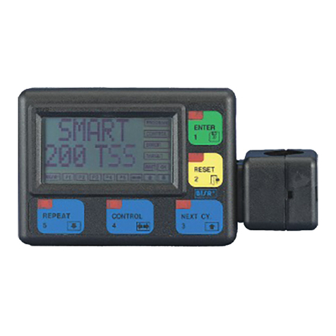
SMART 200 TTS Terminal Features
As in all SMART BTSR systems,the operation of SMART 200 TTS system is
controlled by just 5 membrane buttons and it is monitored by a LCD graphic
display, which guides the operator through all programming and administration
phases of the system, by means of straight-forward messages which can be
understood clearly and immediately.
On the top left hand side of each button there is a red LED, which indicates that the
button is pressed down.
The display screen includes two separate zones used respectively for displaying
operator messages or graphics during the system programming and
administration phases and for signalling the operating status and levels in which the
system is working .
The following picture shows the location of the buttons and display zones that
constitute the control panel of the SMART 200 TTS system.

Operation
- 3.2 - SMART 200 TTS
1. ENTER button
It allows you to activate the function selected from the menu (indicated by the
symbol >), to move to the programming of the displayed function or to confirm the
setting value displayed on the messages screen.
2. RESET button
It allows you to return to the previous level of the menu (upper level), without
continuing with the currently selected function, or without confirming the value of
a setting entered by mistake.
3. NEXT CY button
During navigation within the menus this button allows you to select the next
option within the same menu level; this button has a cyclical function in the
sense that when the last choice from the menu has been selected, it returns to the
first option of the same menu.
When alphanumeric data are entered (for instance the Article Name or Keycode
access), this button allows you to increase the character displayed where the
cursor is located, according to the following cyclic sequence:
When entering numeric data (for example the number of sensors) it allows you
to increase the numeric value of the field. If it is held down continuously the
numeric field increments more rapidly.
4. CONTROL button
During parameter programming, it allows changing the position of the cursor.
5. REPEAT button
During navigation within the menus this button allows you to select the
previous option within the same menu level; this button has a cyclical function
in the sense that when the first choice of menu is selected it returns to the last
option of the same menu.
When alphanumeric data are entered (for instance the Article Name or Keycode
access), this button allows you to decrease the character displayed where the
cursor is positioned, according to the following cyclic sequence:
When entering numeric data (for example the number of sensors) it allows you
to decrease the numeric value of the field. If it is held down continuously the
numeric field decrements more rapidly.

Operation
SMART 200 TTS -3.3 -
6. Operator’s Message Area:
The menu choices, or settings for the selected function during programming or
setup phase of the system as well as service messages are displayed with large size
fonts (1.5 x 0.8 cm), easy to read even from a distance, when the system is running
normally. In other words, it shows all the necessary information to guide the
operator step by step through the programming phase and interactive management
of the system.
When the displayed lines refer to the menu items, the selected one is indicated with
the symbol >.
The presence of a flashing cursor (---) indicates the position where the operator
can enter an alphanumeric character or variable setting which will replace the value
currently displayed.
When you select the GRAPH function from Main Menu, this area is used to
graphically represent the number of twisting detected by a specific sensor, or to
compare by means of a histogram the readings of multiple sensors (8, 12, 16).
7. Operating Status Signalling Area
To enable a more direct and evident interpretation of the operating context in
which you are working, on the right hand side and bottom side of the operator
message area, 16 rectangular boxes (labels) are implemented. They display the
operating status of the system, and the hierarchic level of the menu at which you
are operating.
More specifically, the PROGRAM label indicates that you are operating in one of
the following modes: configuration, programming or data transmission to the
sensors.
The CONTROL label indicates that the system is operating normally with all
monitor functions enabled, and according to the parameters currently set in the
system. In this phase the message display indicates CONTROL OK.
The ERROR label indicates that an error has been detected during normal
operation of the system. In this case the Message area shows the type of error
detected (for further information please refer to Operations Sequences in this
chapter and to chapter 4 – Troubleshooting and Maintenance).
The labels P1 .. P5 indicate the hierarchic level of the menu in which you are
operating. P1 is the highest level, P5 is the lowest hierarchical level. To move
from an upper to a lower level you must normally press down the ENTER button,
while to do the opposite, i.e. going from a lower to an upper level you must press
the RESET button.
SMART
200 TTS

Operation
- 3.4 - SMART 200 TTS
IS3W/TTS Sensor Features
The IS3W/TTS devices are electronic sensors able to detect, due to sophisticated
control technique, the image variation, signalling possible failures detected during
the twisting process of yarns. Thanks to the image variation technique,
ambient/yarn conditions like humidity, conductivity and machine vibrations cannot
influence the IS3W/TTS device, furthermore the image variation technique
requires no contact with the yarn and allows a perfect monitoring without affecting
the characteristics (e.g. tension) of the yarns. IS3W/TTS devices can be used for
yarn quality control (under both static and dynamic conditions) which, thanks to an
innovative patented technique (Smart Scanning Sensor) combined to the advanced
yarn control terminal SMART 200 TTS don't need complex wirings and long
installation times, allowing you to manage up to 200 positions.
The IS3W/TTS devices are very easy to use as they are ready to accommodate a
large variety of accessories that make them suitable to the quality control of any
type of yarn.
Function of the IS3W/TTS Sensors
The function of IS3W/TTS is to control whether the number of twisting applied to
the yarn is within the expected range for the article being processed.
Depending on type of yarn and application, the user can define the minimum and
maximum number of acceptable twisting and, accordingly, program the sensors in
such a way that, when exceeding the defined values, they signal the failure and, if
required, stop the position (STOP output).
In additional the sensor can be configured to perform the control in two different
modes (TT or TB):
1. TT Mode: the sensor analyses the profile of twisted yarns running inside the detection area
and calculates the number of twisting, thanks to the image variation.
In this operating mode, the two yarns, already twisted, run continuously inside the
detection area as shown on figure 1.
2. TB Mode: the sensor analyses the entry/exit movement (balloon) of one of the two yarns
(to be twisted) to/from the detection area, to calculate the number of twisting.
In this operating mode, the internal yarn runs outside the detection area, while the
external yarn enters/exit the detection area, according to the balloon, as shown on
figure 2.
The TT mode is suitable for non hairy yarns (tyrecord) showing a regular profile, while the TB mode is
suitable for hairy yarns that could alter the profile.

Operation
SMART 200 TTS -3.5 -
Technical Characteristics of IS3W/TTS Sensor
Detection area and mechanical layout
(mm)
= yarn detection area
Connection cables
The IS3W/TTS are available as standard version without connection cable. In this
case the wiring can be made using a multi-connector cable MA../..CR which
considerably simplifies the installation in most applications.
For particular application, however , the sensor can be delivered with built-in
single connector cable.
Installation of IS3W/TTS sensors using multi-connector cable
Using multi-connector cable you can interconnect up to 40 sensors for each chain
and then connect the chains to PSU 10 A power supply or directly to SMART 200
TTS terminal (in case of single or double chain). To perform the installation
operate as following:
Select the appropriate multi-connector cable.
Open the small cover on the rear side of sensor.
!Insert the cable’s male connector into the sensor’s female connector (the
reference tab on male connector must be faced towards the upper side).
"Close the small cover and secure the sensor using M3 screws.
#Ensure that the yarn runs in the middle of detection area .

Operation
- 3.6 - SMART 200 TTS
Installation of IS3W/TTS sensors with built-in cable
When you use the IS3W/TTS sensor with built-in cable, independently of the type
of connector used, the wire assignment will always be the following:
Sensor – Operator and Sensor – System Interfaces
Sensor – Operator Interface
The interface between sensor and operator consists of the following:
1 optical button (Touch Light) used by the operator to number the sensor
during the first installation or replacement, to activate/deactivate the sensor and
to reset the sensor after a failure.
To switch the touch light, just skim it with a finger.
2 signally Leds (green ad red) indicating the sensor’s status (initial numbering
status, normal operation status, failure condition and type of failure).
VCC Red
GND White
RX-TX Blue
STOP Black
Touch Light
(embedded green and red Leds)

Operation
SMART 200 TTS -3.7 -
Touch Light Function
Failure Reset: When the sensor is in Failure Status (Red Led blinking) by
skimming the touch light you reset the failure and, after the
programmed Delay-Control time, the sensor resumes the
control.
Numbering: When the sensor is in Numbering Status (Green Led blinking),
by skimming the touch light, you give the sensor the
identification number shown in
Dev *y*…zzz.
Activation/
De-Activation: When the sensor is either in Control or Delay-Control phase,
by skimming the touch light you will either deactivate or re-
activate the sensor itself.
This function can be either enabled or disabled using parameter
LOCK-UNLOCK.
Interpretation of the signalling lights located on the sensors
Green Led ON Normal operation in CONTROL mode;
No defects detected by the sensor.
Green LED FLASHING Normal operation in MONITOR mode
Sensor under automatic numbering procedure.
Sensor in Delay Control phase
Sensor disabled via software
Red LED FLASHING During machine operation the sensor detected a
defect.
1 flash TPX-L error (*)
2 flashes TPX-H error (*)
Green LED ON
Red LED ON
Sensor locked. Switch off and on the system. If the
condition persists, replace the sensor.
Green LED OFF
Red LED OFF
Sensor not powered (check connections).
Sensor de-activated (“Touch Light” skimmed); to
re-activated it, skim again the “Touch Light”.
Green LED FLASHING
Red LED FLASHING
Indicates a sensor fault (e.g. Loss of stored data).
Try to reprogram the sensor.
If the fault remains, replace the sensor
(*) for more details, please refer to paragraph “Parameters that affect the sensor
detection features” page 3.10

Operation
- 3.8 - SMART 200 TTS
Sensor –System Interface
The sensor communicates with SMART 200 TTS terminal and with the textile
machine through the following signals:
TX-RX: Is the bi-diretional communication line between sensor and
SMART terminal, used for sensor operation parameters
programming, for sensor’s test and for all the other real-time
communications between sensor and terminal.
STOP Output: The STOP signal is an OPEN COLLECTOR Output through
which the IS3W/TTS sensor signals the yarn control status
(number of twisting within the minimum-maximum programmed
range or number of twisting higher than the maximum threshold
or lower than the minimum threshold).
The STOP Output can be configured as a Normally Open (NO) or
Normally Closed (NC) signal and, in addition, it can be
configured either as Continuous signal (CONT) or as a 2 seconds
Pulse signal (P2s) or 10 seconds Pulse signal (P10s).
Examples:
Normal Operation = (the yarn runs normally and the number of twisting is within the
programmed range TPX MAX and TPX MIN)
Delay Control = Delay programmable via software
Failure Reset= Either Manual through (Touch Light) or Automatic if RES-MA
parameter is set to Auto.
When the sensor is de-activated, the STOP Output is always in Normal
Operation condition therefore, in case of NO configuration it will always be
an open circuit.
This manual suits for next models
1
Table of contents
Other btsr Control System manuals

btsr
btsr MATRIX CUBE User manual

btsr
btsr SMART MATRIX WINDINGFEEDER User manual

btsr
btsr WINDINGFEEDER User manual

btsr
btsr SMART KTF 2000 User manual

btsr
btsr SMART WARP User manual

btsr
btsr ULTRAFEEDER User manual

btsr
btsr DIAPERFEEDER IP54 DUOLOOP User manual

btsr
btsr SMART 3000TW User manual

btsr
btsr IS3 User manual

btsr
btsr SMART MATRIX QUILT User manual
Popular Control System manuals by other brands

JETI model
JETI model duplex DC -24 II user manual

Norac
Norac Rogator 700 Series installation manual

Pentair
Pentair EASYTOUCH PL4 user guide

Calpeda
Calpeda PFC-M Original operating instructions

Magnetic
Magnetic MHTM MicroDrive Access XL2 operating instructions

EOS
EOS LSG-Steam Installation and operation manual