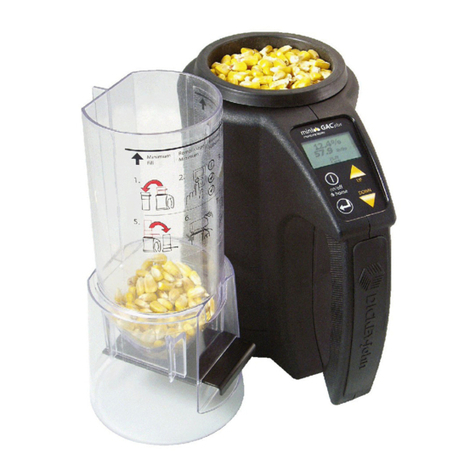
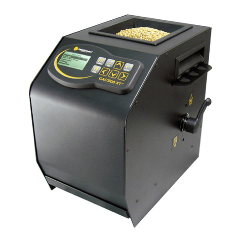
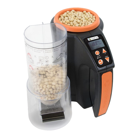
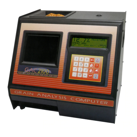
Dickey-John gac 2100 blue User manual

GAC®
2100 GRAIN
ANALYSIS COMPUTER
MODELS BLUE, GRAY, AND AGRI
Operator’s Manual
SINCE 1966
®

OPERATOR’S MANUAL
GAC
®
2100 Grain Analysis Computer (Blue, Gray, Agri Models)
11001-1688-201609
/I
Safety Notices ..................................................................................................... 1
Disclaimer ......................................................................................................................... 1
Introduction ......................................................................................................... 3
Accessories ....................................................................................................................... 3
Features ............................................................................................................................ 4
Specifications .................................................................................................................... 4
Access Codes ................................................................................................................... 5
External Communication Connections .............................................................................. 5
Printer ............................................................................................................................... 6
Unpacking the Instrument .................................................................................. 7
Disengage Shipping Brace ............................................................................................... 7
Instrument Placement.........................................................................................................8
Installation ......................................................................................................... 11
Connecting AC Power ..................................................................................................... 11
Sample Drawer Bypass .................................................................................................. 12
Navigation .......................................................................................................... 13
Display Screen ................................................................................................................ 13
Adjust Screen Contrast ................................................................................................... 13
Keyboard Layout ............................................................................................................. 13
Alarm ............................................................................................................................... 14
Key Functions ................................................................................................................. 14
Menu Screens ................................................................................................................. 15
Startup Procedure ............................................................................................. 17
Test Samples (Quick Start)...............................................................................................18
Measure Moisture ...............................................................................................19
Basic Method .................................................................................................................. 20
Grain Sample ID Numbers .............................................................................................. 22
Enter Numbers and Alpha Characters ............................................................................ 22
ID Options ....................................................................................................................... 23
Factors (Labels) .............................................................................................................. 23
Next Page View .............................................................................................................. 24
Grain Selection .................................................................................................. 25
Select Grain Menu .......................................................................................................... 25
Quick Keys ......................................................................................................................26
Calibrate Procedures ........................................................................................ 27
View Calibration Data (1 Key) ......................................................................................... 27
Enter/Change Calibration Values (2 Key) ....................................................................... 28
Print Calibration Grain List (3 Key) ................................................................................. 31
Obtain Basic Calibration Data (4 Key) ............................................................................ 32
Print Audit Memory Data (5 Key) .................................................................................... 34
Memory Full ................................................................................................................................... 36

OPERATOR’S MANUAL
GAC
®
2100 Grain Analysis Computer (Blue, Gray, Agri Models)
11001-1688-201609
II /
Instrument Setup .............................................................................................. 39
Clear Cycle Counter (1 Key) ........................................................................................... 39
ID Options (2 Key) .......................................................................................................... 40
Configure Output Options (3 Key) .................................................................................. 41
Change The Access Code (4 Key) ................................................................................. 44
Change Date, Time and Date Format (5 Key)..................................................................46
Change Labels (6 Key) ................................................................................................... 48
Set Communications Port Parameters (7 Key) ............................................................... 51
Non-Active (5 Key from Communications Menu) ........................................................... 58
Service Menu (8 Key) ..................................................................................................... 58
Quick Keys Menu ........................................................................................................... 58
Test Weight Bias Adjustment ......................................................................................... 59
Test Weight Slope Adjustment ....................................................................................... 61
Moisture Bias Adjustment ............................................................................................... 62
Moisture Slope Adjustment ............................................................................................. 64
Test Unit Performance ..................................................................................... 67
Non-Active Keys ............................................................................................................. 67
View COM1 Port (2 Key) ................................................................................................ 67
View COM2 Transmit Port (3 Key) ................................................................................. 68
View Display Characters (5 Key) .................................................................................... 69
View Diagnostic Mode (6 Key) ....................................................................................... 70
Test Network Mode (7 Key) ............................................................................................ 72
View/Print Parameters (8 Key) ....................................................................................... 73
Operator Maintenance ..................................................................................... 77
Cell Cleaning - Daily ....................................................................................................... 77
Fuse Replacement ......................................................................................................... 77
Error Codes......................................................................................................... 78
Appendix A: Communication Ports ................................................................ 79
COM1 Port options ......................................................................................................... 79
COM1 Pin Assignment Details ....................................................................................... 79
COM2 Pin Assignment Details ....................................................................................... 80
Warranty.............................................................................................................. 83

OPERATOR’S MANUAL
GAC® 2100 Grain Analysis Computer (Blue, Gray, Agri Models)
11001-1688-201609
1
SAFETY NOTICES
Safety notices are one of the primary ways to call attention to potential
hazards.
This Safety Alert Symbol identifies important safety messages in this
manual. When you see this symbol, carefully read the message that
follows. Be alert to the possibility of personal injury or death.
Use of the word WARNING indicates a potentially hazardous
situation which, if not avoided, could result in death or serious
injury.
Use of the word CAUTION with the Safety Alert Symbol indicates a
potentially hazardous situation which, if not avoided, may result in
minor or moderate injury.
Use of the word CAUTION without the safety alert symbol
indicates a potentially hazardous situation which, if not avoided,
may result in equipment damage.
DISCLAIMER
DICKEY-john reserves the right to make engineering refinements or
procedural changes that may not be reflected in this manual. Material
included in this manual is for informational purposes and is subject to
change without notice.

OPERATOR’S MANUAL
GAC® 2100 Grain Analysis Computer (Blue, Gray, Agri Models)
11001-1688-201609
2 SAFETY NOTICES

OPERATOR’S MANUAL
GAC® 2100 Grain Analysis Computer (Blue, Gray, Agri Models)
11001-1688-201609
INTRODUCTION 3
INTRODUCTION
The DICKEY-john Grain Analysis Computer GAC®2100 quickly tests grain
samples for moisture content and other profile information. The unit loads a
sample, weighs and checks temperature, runs the test, displays the results,
and unloads the sample.
NOTE: Three models are addressed in
this manual and include the
GAC®2100 Blue (BIAS9),
GAC®2100 AGRI (AGZ/AGIA),
and GAC®2100 Gray (GZ/
GIA). Differences in models are
indicated.
Test results calculate automatically to display the moisture content. If
enabled, the temperature and approximate test weight (density) of the grain
sample will display. The product name, grain calibration date, and sample
ID numbers display for identification purposes.
An additional screen of information includes readings for conductance (D1),
capacitance (D2), weight (D3), and temperature (D4) values along with the
current date and time.
Figure 1
GAC®2100 Instrument
ACCESSORIES
• Drawer p/n 464220420BS1
• Null Modem Adapter DB9 Null Modem Adapter 9 pin p/n 220490001
(computer to unit connection)
• Communication software package to upload calibrations to unit via a
computer (available via email by contacting a DICKEY-john
representative).

OPERATOR’S MANUAL
GAC® 2100 Grain Analysis Computer (Blue, Gray, Agri Models)
11001-1688-201609
4 INTRODUCTION
FEATURES
GAC 2100 features include:
• Memory storage for grain calibrations
– 64 grain calibrations (GAC 2100 Blue)
– 8 grain calibrations (GAC 2100 AGRI)
– 16 grain calibrations (GAC 2100 Gray)
• Keyboard entry or computer accessibility for updating grain
calibrations as revisions become necessary.
• Alpha/numeric sample identification numbers with automatic
sequential numbering for record keeping purposes.
• Automatic ranging by switching to predetermined calibrations when
moisture is above or below normal limits.
• Two RS-232 output ports (DCE and DTE) available for printer and
external computer/modem control.
• Capability to interface with a personal computer either directly or
through a modem (Blue model).
• Self-check mode to ensure proper continual operation.
• Error messages for out-of-limits moisture, grain weight, or grain
temperatures.
• Help screens to address operator issues.
• Quick keys (Blue model)
• Test weight slope and bias adjustment all grains
• Moisture slope and bias adjustment all grains
SPECIFICATIONS
•Supply Voltage and Frequency Limits:
– 85 Vac to 264 Vac 48-440 Hz at 1 Amp Max.
•Operating Temperature Range:
– 2° C (35.6° F) to 45° C (113° F) (Blue model)
–5
oC (41oF) to 45oC (113oF) (AGRI and Gray models)
– If the instrument exceeds temperature ranges, an error displays.
•Grain Temperature Range:
– 0° C (32° F) to 45° C (113° F) (Blue model)
–0
oC (32oF) to 50oC (122oF) (AGRI and Gray models)
If the grain temperature range is exceeded, an error message
displays.
•Unit Temperature and Grain Temperature Difference Limit: The
maximum allowable temperature differential between empty cell and
grain under test is 20° C (36° F). If exceeded, an error message
displays.
•Classes/Types of Grain or Seed: Refer to the latest Calibration
Bulletin.
•Weight: 11.8 kg (26 lbs) – Shipping Weight: 15.0 kg (33 lbs)

OPERATOR’S MANUAL
GAC® 2100 Grain Analysis Computer (Blue, Gray, Agri Models)
11001-1688-201609
INTRODUCTION 5
ACCESS CODES
An access code is necessary to gain access to certain screens. Whenever
the code is required, a screen appears stating ENTER ACCESS CODE.
The factory preset access code is set to “0”. To change the access code for
security reasons, refer to “Changing the Access Code” in “Instrument
Setup” section.
EXTERNAL COMMUNICATION CONNECTIONS
GAC 2100 Blue
The GAC 2100 Blue is capable of communicating with a computer via a
direct connection using a null modem cable.
GAC 2100 AGRI and Gray
The GAC®2100 AGRI and Gray models can output to a personal computer
(PC) using the COM1 or COM2 ports. The two communication ports are
located on the rear of the unit and are identified as Printer Output Port
(COM1) and Computer Output Port (COM2). Each must be properly
configured to communicate with external devices. Port configuration is
described in the Instrument Setup section.
When using the COM2 port, a null cable or null adapter is required. A
null adapter is available from DICKEY-john.
Figure 2
Communication Ports
Access
Port
COM1
Port
COM2
Port

OPERATOR’S MANUAL
GAC® 2100 Grain Analysis Computer (Blue, Gray, Agri Models)
11001-1688-201609
6 INTRODUCTION
PRINTER
An optional printer connected to the instrument can print test data results.
The printout can include:
• Facility name and address
• Current date and time
• Sample ID number
• Product name
• Grain calibration date
• Percent moisture
• Test Weight
• Grain temperature
• Unit serial number
• D1 through D4 values
Data can automatically print at the end of each measurement cycle or
manually initiated by pressing the Print key.
Print Key

OPERATOR’S MANUAL
GAC® 2100 Grain Analysis Computer (Blue, Gray, Agri Models)
11001-1688-201609
UNPACKING THE INSTRUMENT 7
UNPACKING THE INSTRUMENT
DISENGAGE SHIPPING BRACE
The shipping brace must be moved to the operate position before
applying power. Since the grain test cell cycles through an unload
sequence during power up, damage may occur with the shipping
brace in the transport position.
The GAC 2100 is shipped with the grain test cell supported by an internal
shipping/transport brace. This brace supports the test cell whenever the unit
is transported. The position of the brace is controlled by a handle located on
the rear panel behind the grain test cell (Figure 5). A small spool is placed
over the handle to prevent possible bumping and release of the handle
during shipment.
To Disengage Shipping Brace:
1. Remove spool and store with shipping materials.
2. Push the handle in to unlock position and rotate counterclockwise to
the locked operate position as indicated on the back panel.
– The movement of the brace is viewable through the front window of
the unit.
Figure 3
Disengaging Shipping Brace
Shipping Brace Transport Handle
Operate
position
Transport
position

OPERATOR’S MANUAL
GAC® 2100 Grain Analysis Computer (Blue, Gray, Agri Models)
11001-1688-201609
8 UNPACKING THE INSTRUMENT
Rotate the brace back into supporting position before moving or
shipping the unit. If the cell is not adequately supported operating
performance may be adversely affected due to cell bouncing.
Some effort is required to move the brace back into position. It
may be helpful to reach inside the drawer front and lift up on the
cell while attempting to lock the brace into the transport position.
Place the spool over the handle to prevent the accidental release
of the shipping brace.
INSTRUMENT PLACEMENT
Choose a clean environment that is protected from rapid changes in
ambient temperature. Avoid a hazardous (classified) location as defined in
Article 500 of the NFPA Handbook of the National Electrical Code.
Instrument should be placed in a dry environment/area free to
standing water or dampness to avoid electrical shock.
Figure 4
GAC 2100 Dimensions
37.5 cm
(14.75 in.)
40.6 cm (16.00 in.) 38.7 cm (15.25 in.)
Front View
Top View
Side View
GRAIN ANALYSIS COMPUTER
GAC 2100

OPERATOR’S MANUAL
GAC® 2100 Grain Analysis Computer (Blue, Gray, Agri Models)
11001-1688-201609
UNPACKING THE INSTRUMENT 9
To Level the Instrument:
1. Use the self-contained level on the panel top to position the GAC 2100
on a flat level or nearly level surface.
2. Adjust the four rubber foot pads to level and stabilize the unit
(Figure 5). To adjust the foot pad height, unlock the upper nut from the
bottom panel of the selected foot pad and adjust height as required.
– All four leveling foot pads should be set to the lowest level possible
with one pad fully seated against the bottom panel. This ensures
minimum height above the counter top.
– When moving the instrument to a different location, re-leveling may
be required.
3. After adjusting, use a Phillips screwdriver in the center of the foot pad
to hold the screw from turning and tighten the upper nut against the
bottom panel of the unit.
4. Ensure the lower nut remains tight against the foot pad.
Figure 5
Leveling With Rubber Foot Pads
Rubber
Foot Pads
4. After adjustment, retighten nut up against
bottom panel.
1. Use wrench to loosen the upper nut
and then adjust height.
2. Ensure bottom nut is locked down
against rubber foot pad.
3. Use a Phillips screwdriver in center
of pad to change height and to hold
the screw from turning while tightening nuts.

OPERATOR’S MANUAL
GAC® 2100 Grain Analysis Computer (Blue, Gray, Agri Models)
11001-1688-201609
10 UNPACKING THE INSTRUMENT

OPERATOR’S MANUAL
GAC® 2100 Grain Analysis Computer (Blue, Gray, Agri Models)
11001-1688-201609
INSTALLATION 11
INSTALLATION
Before shipping, the GAC 2100 is inspected and tested for mechanical and
electrical defects. After unpacking, visually inspect for possible damage that
may have occurred during transit. Save all packing materials until the
inspection is complete. If damage is found, immediately file a claim with the
carrier and notify your DICKEY-john representative.
CONNECTING AC POWER
1. Verify that the ON/OFF (I/O) switch is in the OFF (O) position and that
the shipping brace is in the OPERATE position.
2. Plug the line cord into the connector on the rear panel next to the ON/
OFF switch.
3. Plug the male end into an appropriate 3-wire (grounded) outlet.
The grounding pin on the line cord connects directly to the
GAC 2100 frame. When using an adapter with a grounding wire
ensure the grounding wire is connected properly to a good earth
ground to prevent a shock hazard.
Figure 6
Connecting Power
Verify Shipping
Brace Transport
Handle is in
Operate
position
Line
Cord
Connector
On/Off
Switch
Display
Contrast
Control
Fuse
Assembly

OPERATOR’S MANUAL
GAC® 2100 Grain Analysis Computer (Blue, Gray, Agri Models)
11001-1688-201609
12 INSTALLATION
SAMPLE DRAWER BYPASS
Normal use of the sample drawer can be bypassed by removing the drawer
bottom and cutting a hole into the work counter to allow the tested grain
samples to fall through to a larger container below. The size of the hole
must be at least equal to the drawer dimension and located directly beneath
the grain sample drawer.
To Remove Sample Drawer Bottom:
1. To remove the bottom of the grain sample drawer, carefully lift the two
plastic tabs at the front of the drawer (Figure 7).
2. Using a small screwdriver, gently pry up on each tab and slide the
bottom panel out the rear of the drawer.
Use care when prying on tabs to prevent breakage.
3. When finished, slide the grain drawer back into position. This prevents
grain from spilling onto the work surface in front of the unit.
– If replacing the drawer bottom later, slide the bottom toward the
drawer front until it latches under the two plastic tabs.
Figure 7
Removing Drawer Bottom
Tab
Tab

OPERATOR’S MANUAL
GAC® 2100 Grain Analysis Computer (Blue, Gray, Agri Models)
11001-1688-201609
NAVIGATION 13
NAVIGATION
DISPLAY SCREEN
The display screen is a graphics Liquid Crystal Display (LCD) and is
backlighted for low light level viewing.
ADJUST SCREEN CONTRAST
The Display Contrast Control is on the rear panel (Figure 6) immediately
above the COM1 and COM2 ports. The contrast control changes the
contrast between the displayed characters and the background. Adjust the
control as necessary for a comfortable contrast level in varying light
conditions.
KEYBOARD LAYOUT
All operator controls, except the Power ON/OFF switch and Contrast
control, are located on the front panel. These two are on the rear panel.
The sealed membrane keyboard contains 20 pressure-sensitive keys
requiring light finger pressure to actuate each key. Valid key closures result
in short tone bursts while invalid keystrokes generate longer tone bursts.
The function of each key or key group is defined as follows and illustrated in
(Figure 8).
Numbers (0 through 9), Decimal point (.) and Minus (–) keys
All numeric keys perform dual functions, making menu selections, and
entering numeric values. The four numeric keys with small arrows have the
additional function of screen navigation. When making a numeric entry, a
prompt on the display identifies the value entered and a cursor shows the
destination of each entry. The minus (-) sign is accepted at any point in the
entry and displays at the front of the entered string.
Figure 8
Keyboard Layout
Each entry immediately displays as the cursor moves to the right in
preparation for the next entry. Only the first entry of the decimal point is
acknowledged.
7
1
89
456
23
0
.–
Keys 0, 1, 3, and 5
also function as
arrow keys to navigate
to certain screens.

OPERATOR’S MANUAL
GAC® 2100 Grain Analysis Computer (Blue, Gray, Agri Models)
11001-1688-201609
14 NAVIGATION
ALARM
An audible alarm is enabled for 0.5 seconds at the end of each grain
analysis or for an error condition. A shorter beep of 0.1 seconds sounds for
each valid key stroke.
KEY FUNCTIONS
BACKSPACE KEY
Moves the cursor to the left to delete the last keystroke or to clear an entire
entry field.
NEXT PAGE KEY
Advances to the next page when the <more> prompt appears in the lower
right corner of the display. The Next Page key sequences the display
forward to additional pages of information. The total page number and page
count appear in the lower left corner of screen (i.e. PAGE 2 OF 8).
Figure 9
Typical Screen Indicating More Pages
PREVIOUS PAGE KEY
Sequences backward through previously displayed pages. Neither the
Previous Page or Next Page keys roll-over the pages to the beginning or
end.
ENTER KEY
Accepts the character string after an entry is complete.
LOAD KEY
Initiates a grain cell loading sequence to begin a test cycle.
HELP KEY
Provides context-sensitive help screens on the display. If the <more>
message appears at the lower right of the screen, additional pages are
accessible with the Next Page key. To use the HELP INDEX when in a Help
screen, select the 0 key and select the desired topic. To resume normal
operation, select the Help key a second time.
SELECT GRAIN
1: CORN 5: SOYBEANS
2: CORN HI MOIST 6: FESCUE
3: WHEAT HRW 7: BARLEY
4: OATS 8: RYE
PAGE 1 OF 8 <more>
Indicates
Additional Page
Indicates Number
of Pages

OPERATOR’S MANUAL
GAC® 2100 Grain Analysis Computer (Blue, Gray, Agri Models)
11001-1688-201609
NAVIGATION 15
PRINT KEY
Initiates a printout of current information on the screen (e.g., grain moisture
analysis, calibrations data, etc.). If the automatic printout option is selected,
the Print key initiates duplicate copies. Help information does not print.
COM SETUP options allows the Print key to transmit to either the printer
port or the communications/modem port. For example, the system may be
configured to automatically print results through the printer port while the
Print key transfers results to the computer port.
UNLOAD KEY
Dumps the contents from the test cell after a grain test.
LEFT AND RIGHT KEYS
Moves the cursor horizontally during alpha entries and certain functions
during the SETUP mode.
UP AND DOWN KEYS
Moves the cursor vertically during alpha entries and certain functions in the
SETUP mode.
MENU SCREENS
The Main menu displays once the start-up checks are successfully
completed. The Main menu is the “home” screen that all other screens are
accessed. The Main menu displays five major selections or categories.
A number appears next to each Main menu selection. Select the desired
number to access the appropriate menu. Refer to (Figure 11) for a general
configuration of the Menu Tree layout.
Figure 10
Main Menu Selections
1
3
&
50
&
MAIN MENU
1: MEASURE MOISTURE 3: CALIBRATION MENU
2: SELECT GRAIN 4: SETUP MENU
5: TESTS MENU
SELECT ITEM NUMBER (NEXT PAGE: STATUS)
STATUS
CYCLE COUNTER: 435
THIS COUNTER INCREMENTS AFTER EACH
SAMPLE MEASUREMENT OR DATA COLLECTION
SEQUENCE IS SUCCESSFULLY COMPLETED

OPERATOR’S MANUAL
GAC® 2100 Grain Analysis Computer (Blue, Gray, Agri Models)
11001-1688-201609
16 NAVIGATION
Figure 11
Menu Tree
<MORE>
<MORE>
<MORE>
<MORE>
<MORE>
<MORE>
<MORE>
SETUP MENU
MAIN MENU
1: MEASURE MOISTURE
2: SELECT GRAIN
SELECT ITEM NUMBER (NEXT PAGE: STATUS)
3: CALIBRATION MENU
4: SETUP MENU
5: TESTS MENU
FILL SAMPLE HOPPER, ENTER ID NO. THEN
SETUP MENU
1: CLEAR COUNTER
2: ID OPTIONS
3: OUTPUT OPTIONS
4: EDIT ACCESS CODE
SELECT ITEM NUMBER
5: DATE/TIME MENU
6: LABELS MENU
7: COM MENU
8: SERVICE MENU
TESTS MENU
1: non-active
2: COM1
3: COM2 TRANSMIT
4: non-active
SELECT ITEM NUMBER (NEXT PAGE: STATUS)
5: DISPLAY
6: DIAGNOSTIC MODE
7: TEST NETWORK MODE
8: PARAMETERS MENU
CALIBRATION MENU
1: VIEW CALIBRATION
2: ENTER/CHANGE CALIBRATION
3: PRINT CALIBRATION LIST
4: OBTAIN CALIBRATION DATA
5: PRINT AUDIT MEMORY DATA
SELECT ITEM NUMBER (NEXT PAGE: STATUS)
<MORE>
PRESS LOAD TO BEGIN
CORN 91051
ID: 2
PAGE 8 OF 8
PAGE 7 OF 8
PAGE 6 OF 8
PAGE 5 OF 8
PAGE 4 OF 8
PAGE 3 OF 8
PAGE 2 OF 8
PAGE 1 OF 8
SELECT GRAIN
1: CORN
2: CORN HI MOIST
3: AMARANTH
4: BARLEY
5: SOYBEANS
4: DURUM
5: FESCUE
8: MILLET
GAC 2100 Blue
SELECT GRAIN
1: CORN
2: CORN HI MOIST
3. SOYBEANS
4: SORGHUM
5: WHEAT HRW
6: WHEAT HRS
7: WHEAT SRW
8: OATS
GAC 2100 AGRI
<MORE>
PAGE 2 OF 2
PAGE 1 OF 2
SELECT GRAIN
1: CORN
2: CORN HI MOIST
3: SOYBEANS
4: SORGHUM
5: WHEAT HRW
6. WHEAT HRS
7. WHEAT SRW
8: OATS
GAC 2100 Gray
Calibration Menu on the AGRI and Gray
instruments do not have
5. Print Audit Memory Data.

OPERATOR’S MANUAL
GAC® 2100 Grain Analysis Computer (Blue, Gray, Agri Models)
11001-1688-201609
STARTUP PROCEDURE 17
STARTUP PROCEDURE
Each time the GAC 2100 is powered on, the instrument performs a series of
self checks to determine the status of the following:
• Load/strike-off mechanism
• Unload function
• Empty test cell weight
• Conductance/capacitance measurement circuitry
Self-checks begin when the hopper doors open, the strike-off arm swings
across the cell and back again, and the cell dumps. When the cycle ends
(about 15 seconds), the Main Menu displays.
Before starting the following procedures, ensure the ON/OFF (I/O)
switch is in the OFF (O) position and that the shipping brace is in
the OPERATE position. These are both located on the rear of the
unit.
1. Turn the power switch ON. Initially, a language screen appears
showing eight choices (Figure 12). Two English selections are
available: English US and English.
– English US invokes parameters to display test weight for
NTEP-certified calibrations used in the United States and allows the
option of displaying test weight on the Analysis screen.
– English is for non-NTEP users that do not require test weight
parameters.
Figure 12
Start Up Screens
1: *ENGLISH US
2: NEDERLANDS
3: FRENCH
4: DEUTSCH
5: ITALIANO
6: PORTUGUES
7: ESPANOL
8: ENGLISH
PLEASE WAIT
PERFORMING STARTUP TESTS
GAC2100 REV: 0798121009
LANG REV: 0798121009
Language Software
Number
Instrument
Software
Number
This manual suits for next models
2
Table of contents
Other Dickey-John Measuring Instrument manuals

Dickey-John
Dickey-John mini GAC User manual

Dickey-John
Dickey-John GAC 2500 User manual

Dickey-John
Dickey-John MINI GAC 2500 NBT User manual

Dickey-John
Dickey-John Seed Manager SE User manual

Dickey-John
Dickey-John GAC 2500 User manual

Dickey-John
Dickey-John Dj F-2000 User manual

Dickey-John
Dickey-John gac 2100 agri User manual

Dickey-John
Dickey-John GAC500XT User manual

Dickey-John
Dickey-John GAC 2500 User manual

Dickey-John
Dickey-John C-2000 User manual