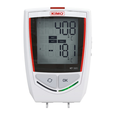
Dickson ES120 User manual

Rev. 02/06
DICKSON
ES120/ES120A
Electronic Signal Data Logger
Contents:
Product Applications and Useful Features
Product Specifications
Product Accessories
Frequently Asked Questions
Transmitter / Sensor
DicksonWare Software Specifications
Operating Instructions / Getting Started
Troubleshooting
Warranty / Factory Service & Returns
Order Form
Applications,
Features, &
Specifications
Product
Accessories &
FAQs
Transmitter/
Sensor
DicksonWare
Software
Specifications
Operating
Instructions /
Getting Started
Troubleshooting Warranty/
Factory Service
& Returns
Order Form
DICKSON
ES120

Rev. 02/06
Applications,
Features, &
Specifications
Product
Accessories &
FAQs
Transmitter/
Sensor
DicksonWare
Software
Specifications
Operating
Instructions /
Getting Started
Troubleshooting Warranty/
Factory Service
& Returns
Order Form
DICKSON
Product Applications
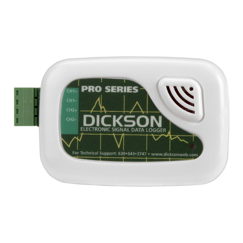
The Dickson ES120 sets a new standard in accurate, easy-to-use, affordable PC based recording. The ES120
will allow simultaneous monitoring of multiple variables with one data logger. With little effort, pressure,
air movement, flow, fluid level, electrical properties, moisture, gas concentrations and much more can be
monitored. Due to its small size and rugged design, the ES120 can be placed just about anywhere!
The ES120 is ideal for researchers, building operators, test & equipment engineers and quality control
personnel. DicksonWare™ makes reading recorded data on your PC easy! Importing data into a Word
document, Excel spreadsheet or PowerPoint presentation is a snap.
Product Features
• Simultaneous monitoring of multiple variables with one data logger
• Monitor pressure, air movement, flow, fluid level, electrical properties, moisture gas concentrations and
much more
• 5 year battery life
• Stores 32,000 sample points (16,000 per channel)
• 2 user selectable channels
Other Useful Features
Delayed Start
Program how many Days, Hours and Minutes must expire before your unit begins logging.
Real Time Monitoring
Monitor and graph your process as it happens and print and save from real time screen. (This feature should
be used sparingly as it causes the battery to drain quicker)
Customize Graphed Data
DicksonWare™ calculates Min, Max and Average of all data collected. Customize data by highlighting
specific data points which will recalculate MIN, MAX and Average for highlighted information.
Export Data
A snapshot of your graph or a real-time graph of points can be easily exported to other programs such as
Excel™ or PowerPoint™.
CLICK ON THE FEATURES BUTTON IN THE SOFTWARE FOR DETAILED INSTRUCTIONS ON HOW
TO USE ABOVE FEATURES AND MORE.
Product Specifications
ES120 ES120A
Operating Range (unit only): -40 to +176˚F -40 to +176˚F
(non-condensing) (non-condensing)
Input: 0 to 5V or 0 to 20mA 0 to 15V
Total Channels: 2 2
Input Connection: Screw Terminal Block Screw Terminal Block
Sample Interval: 10 sec. to 24 hr. interval 10 sec. to 24 hr. interval
Storage Capacity (sample points): 32,000 div. by 2 32,000 div. by 2
Resolution: 0.1˚F 0.1˚F
Dimensions: 3.1” x 2.1” x 0.9” 3.1” x 2.1” x 0.9”
(79mm x 53mm x 23mm) (79mm x 53mm x 23mm)
Weight: 2 oz (56.7 g) 2 oz (56.7 g)

Rev. 02/06
Applications,
Features, &
Specifications
Product
Accessories &
FAQs
Transmitter/
Sensor
DicksonWare
Software
Specifications
Operating
Instructions /
Getting Started
Troubleshooting Warranty/
Factory Service
& Returns
Order Form
DICKSON
Accessories (for current pricing go to www.dicksonweb.com or call 1-800-323-2448)
Software Order #
DicksonWare™ Software and Serial Download Cable A015
Cases
Locking Wall Mount Case A715
Waterproof Pouch A713
Other
Certificate of Validation N520
Frequently Asked Questions
Sample Interval: The Sample Interval determines how frequently the data logger will save a reading.
Using DicksonWare™ Software, the user can set a Sample Interval ranging from 10 seconds to 24 hours in
10 second increments. A temperature logger with data storage of 32,512 set at a 10 second Sample Interval
will record for 3.75 days, while the same logger set at a 1 minute Sample Interval will record for 22.5 days.
Data Storage: Data Storage is the number of Sample Points a data logger can hold. You will find models
that range from 7,680 samples to 32,512. A temperature logger with Data Storage of 32,512 and a sample
interval set at 30 seconds would record for 11.25 days, while a temperature logger with Data Storage of
7,680 and the same sample interval would record for only 2.6 days.
Does it have to stay connected to a PC in order for it to work? No. Unless you’re viewing data in
real-time you only connect the logger to a PC when you want to view / retrieve data.
What happens when all the storage space is taken up? Do I have to throw it away?
After you have downloaded the data, you simply “clear” the logger and it is ready to log more data.
What happens if I leave it monitoring somewhere too long? The Data Loggers have two user
selectable modes, Stop and Wrap. In Stop mode, they will quit logging data when the memory is full. In
Wrap mode, the Logger will begin to overwrite the oldest data in its memory.
Where can I put them? Depending on the Dickson model, just about anywhere. We have waterproof
units, stainless steel models, units with probes, and units that handle extreme temperatures. Our wide
selection of instruments should fit about any application.
What is the biggest advantage of a Data Logger? Its data is “logged”, stored on a microchip inside
the Data Logger. Data in electronic memory takes advantage of the power of a PC and software.
* Store the data as you would store any document on your PC.
* Retrieve archived data as easily as opening a file on your PC.
* Share the data as you would any PC file, email, copy and paste.
* Data can be imported into spreadsheet software and word processing documents.
* Easily import data from multiple data loggers onto a single graph.
How are they mounted? The smallest ones, about the size of a pager, can be wall-mounted with Velcro
or simply set anywhere you need to monitor. The larger units have keyhole slots for wall mounting and can
also stand on their own.

Rev. 02/06
Applications,
Features, &
Specifications
Product
Accessories &
FAQs
Transmitter/
Sensor
DicksonWare
Software
Specifications
Operating
Instructions /
Getting Started
Troubleshooting Warranty/
Factory Service
& Returns
Order Form
DICKSON
Transmitter / Sensor
+
-
+
-
+
-
Power Supply Transmitter 1
Transmitter 2
ES120-A
CH1
CH1
CH2
CH2
IN Voltage
SIG OUT
GND
IN Voltage
SIG OUT
GND
Typical Setup,
Voltage (V)
A powered transmitter is required to operate the ES120/ES120A.Any powered transmitter with a 4-20mA,
0-20mA, 0-5Vdc, 1-5Vdc or 0 to 15v (ES120A) output signal may be used. To connect a transmitter to the
logger, locate the terminal block on the side of the logger. Connect the positive wire of the transmitter to
the positive terminal and the negative wire of the transmitter to the negative terminal of the appropriate
channel. Tighten screws in terminal block to hold in transmitter wires. Repeat steps with second transmitter.
+
-
+
-
+
-
+
-
+
-
Power Supply Transmitter 1
Transmitter 2
ES120
CH1
CH1
CH2
CH2
+
-
+
-
+
-
Power Supply Transmitter 1
Transmitter 2
ES120
CH1
CH1
CH2
CH2
IN Voltage
SIG OUT
GND
IN Voltage
SIG OUT
GND
Typical Setup,
Current (mA)
Typical Setup,
Voltage (V)
ES120
ES120A

Rev. 02/06
Applications,
Features, &
Specifications
Product
Accessories &
FAQs
Transmitter/
Sensor
DicksonWare
Software
Specifications
Operating
Instructions /
Getting Started
Troubleshooting Warranty/
Factory Service
& Returns
Order Form
DICKSON
DicksonWare™ Software Specifications
• Microsoft Windows® compatible
• Allows for simple viewing and zooming of logged data
• Easy set-up of Dickson Data Loggers including:
• User selectable sample intervals from 10 seconds to 24 hours
• Display temperature in °C or °F
• Delayed logger start times
• Logger data capacity can be set to wrap data or stop when full
• Allow for real time monitoring and graphing.
• Effortless exporting of data and graphs to other software
• Data can be viewed in tabular (numeric/table) or graphical formats
• Fast downloading of logged data - 30 seconds (typical) from full logger
• Even shows battery power status for battery operated loggers
Specifications:
Compatible With: Microsoft Windows® 95, 98, 2000, NT & XP
PC Requirements: PC with 386 MHz or better microprocessor, 4 M RAM, 1 free COM (serial) port, CD
drive
Cable Type/Length: 9 pin male D-shell to male 2.5mm stereo plug, 6’ long
Computer Interface: RS-232 COM (serial) port
DicksonWare™ Version Required (minimum): See Specific Model for Version Requirement

Rev. 02/06
Applications,
Features, &
Specifications
Product
Accessories &
FAQs
Transmitter/
Sensor
DicksonWare
Software
Specifications
Operating
Instructions /
Getting Started
Troubleshooting Warranty/
Factory Service
& Returns
Order Form
DICKSON
Operating Instructions
• Install the DicksonWare™ Software.
• Connect the cable (supplied with the software) to the logger and to a working serial port on your
computer.
ES120 Setup
• Ensure dip switch settings. Remove the screw on the back of the case and position the switch for each
channel according to the type of signal being supplied, ON for 0 to 20mA Current signal and OFF
for 0 to 5Vdc signal.
• Connect your 0 to 5Vdc and/or 0 to 20mA transmitter(s) using the channel polarity indicated on the
front label.
ES120A Setup
• Connect your 0 to 15Vdc source or transmitter(s) using channel polarity indicated on the front label.
DO NOT CHANGE DIP-SWITCH SETTINGS FOR ES120A.
Getting Started
• Click the Setup button. When the setup window appears, all fields should be automatically filled in, this
will confirm that DicksonWare™ has recognized the logger. Should all fields remain blank, refer to “No
Communication” in the Trouble Shooting section of this manual.
• Once DicksonWare™ recognizes the logger, select the channels tab. Press the adjust button next to the
desired channel which will bring up a channel adjustment window with two categories, ENABLE and
USER DEFINED. In the “Enable” section, the “Enable” box should be deselected. If a channel is not
going to be used, this will allocate all storage capacity to the active channel. You may also choose to
change the label for that channel to reflect the actual variable being measured such as Temperature,
Pressure or Flow.
Following Setups Are For ES120 Models Only
In the “User Defined” section, set the MIN and MAX input signal being supplied by your transmitter, units
should show mA or V depending on what type of signal that channel is setup to receive. Now set the MIN
and MAX range that applies to the programmed input signal.
Changing these parameters in the ES120A model will cause the logger to operate improperly.
You may also want to type a variable in the units field that represents what is being measured such as F for
Fahrenheit, PSI for pressure or gpm for gallons per minute. You may set the units for model ES120A as well.
• To start logging, press the Clear button. This will delete all data currently stored.
• The logger is now sampling and ready for use. The default sample interval is 1 minute. Verify that the
indicator light is flashing every 10 seconds. You may choose to change Default settings for sample
interval and start-date and time. When changing these settings, the logger will automatically go
through the clear process to accept your changes.
NOTE: To conserve battery life when storing unit, press the Setup button and select the shortest Sample
Interval and Stop When Full in the Samples section.

Rev. 02/06
Applications,
Features, &
Specifications
Product
Accessories &
FAQs
Transmitter/
Sensor
DicksonWare
Software
Specifications
Operating
Instructions /
Getting Started
Troubleshooting Warranty/
Factory Service
& Returns
Order Form
DICKSON
Troubleshooting
No Communication
• Verify that you have the correct version of Dickson software installed on your PC. Version 6.0.2.1 or
higher is required for model ES120. Version 6.0.3.10 or higher for model ES120A.
• Verify that the correct COM port is selected: From the main DicksonWare™ screen, click on Logger then
Communication, a black dot will appear next to the selected COM port. You may need to select a
different COM port. Should you get an error message stating that “Device Is Already Open”, this could
mean that you have the proper COM port selected, but another device, or it’s software, has it allocated.
Palm pilots, for example, will cause this problem, in which case the port is not actually available and
you may have to disable that device.
You may need to relocate the download cable to another serial port on the back of the PC and possibly try
changing the COM port again in DicksonWare™.
• If communication has not been established with the previous steps, you may need to open the logger and
press the reset button and then try all COM port and cable combinations again.
• If possible, try another PC
Indicator
There is a red indicator located on the front lower right corner of the unit. This indicator will flash every 10
seconds ONLY when the unit is sampling and operating properly. If the indicator is not flashing, please verify
the following:
• The logger memory may be full; download the data and clear the memory.
• Sampling may not be activated. To start sampling clear the memory.
• Condensation may have formed on the unit. Place unit in a warm dry environment for 24 hrs. Clear
memory and try again.
These loggers are designed for use in a non-condensing environment. If the environment creates
condensation, try placing the unit (temperature only models) in a small sealed plastic bag to protect it from
condensation.
If the logger appears to be malfunctioning, try the following:
• Open the unit by removing the screw in the back of the case and press the small black RESET button
located on the circuit board inside. Try the logger operation again.
NOTE: Pressing the reset will not erase stored data, but will stop future logging until the logger memory is
cleared.
USB to Serial adapter use
If you do not have an available dedicated serial port to use for communications with the logger, you may use
a 3rd part USB to Serial adapters which are readily available from any electronic or computer store.
Setup: These adapters have a serial communications port and a USB communications port. The USB
communications port will connect to your computer and the serial communications port will connect to the
logger. These adapters will also have a software driver that may need to be installed before use and a setup
guide to walk you through the installation of the USB to Serial adapter. Once the adapter is setup, your
computer will have a new serial communications port that will be available for use.
Use: The USB to Serial adapter has to be plugged into the computer before opening DicksonWare software,
you cannot attach the adapter after DicksonWare is already running. DicksonWare must be set for serial
communications, not USB communications in order to communicate to a datalogger at the end of a USB to
Serial adapter.
Battery
The battery will operate the logger for 5 years at room temperature. Operation of the logger at the
temperature extremes, in real-time mode for prolonged periods, or sample intervals of less than a minute,
will significantly reduce battery life. Please contact the factory if the battery requires replacement. The
Battery Level Monitor on the Setup screen displays the battery voltage and a Low Battery Warning when
replacement is needed.
Please visit: www.dicksonweb.com for complete troubleshooting guide or call 630-543-3747

Rev. 02/06
Applications,
Features, &
Specifications
Product
Accessories &
FAQs
Transmitter/
Sensor
DicksonWare
Software
Specifications
Operating
Instructions /
Getting Started
Troubleshooting Warranty/
Factory Service
& Returns
Order Form
DICKSON
Warranty
Dickson warrants that the products it sells will be free from defects in material and workmanship under
normal use and service for a period of twelve months after delivery. In the event of a claim under this
warranty, the product or part must be returned to the factory for repair or replacement (shipping pre-paid)
with a Return Authorization Number (see Return Information above). It will be repaired at Dickson’s option
without charge. This warranty DOES NOT cover routine calibration, pen, chart and battery replacement. The
foregoing warranty and remedy are exclusive and in lieu of all other warranties either expressed or implied.
Dickson shall not be liable for consequential or incidental damages resulting from failure or malfunction of
its products. Dickson makes no warranty for products not manufactured by it or for any products modified by
buyer, or subject to misuse or neglect.
Factory Service & Returns
Contact the factory (630-543-3747) for a Return Authorization (RA) Number before returning any
instrument. The model number, serial number and a purchase order number will be requested before an RA
number is issued.
• Carefully repack the instrument, label the outside of the box with the RA# and return the instrument
(freight pre-paid) to Dickson.
• All instruments that do not have the RA# clearly marked on the outside of the box will be refused. When
returning instruments for credit, please include all accessories in shipment.
• Calibration/Freight charges are non-refundable.
NOTE: Dickson shall not be liable for consequential or incidental damages resulting from failure or
malfunction of its products.
Customer Satisfaction
Dickson takes pride in providing you, the customer, with the highest quality instrumentation. We welcome
the opportunity to help you in any way possible. Whether it be a question or a new idea in documentation,
the Dickson Company would like to hear your response. Please call our Customer Service Department at
1-800-323-2448 or (630) 543-3747 (in Illinois).
Software Return Policy
IMPORTANT-Read your Software License Agreement carefully before installing software. DIckson will accept
returns for replacement of defective disks and CDs only.
DICKSON
930 South Westwood Avenue
Addison, Illinois 60101
Phone: (630) 543-3747 • E-mail: DicksonCSR@dicksonweb.com
Applications,
Features, &
Specifications
Product
Accessories &
FAQs
Transmitter/
Sensor
DicksonWare
Software
Specifications
Operating
Instructions /
Getting Started
Troubleshooting Warranty/
Factory Service
& Returns
Order Form
DICKSON
Step 1 - Bill To:
Name
Company
Address
City
State Zip
Phone ( ) –
Email
Step 2 - Ship To (if different than above)
Name
Company
Address
City
State Zip
Phone ( ) –
Email
Step 3 - Ordering Information
Order # Quantity Price/Unit Total
$ /each $
$ /each $
$ /each $
$ /each $
Subtotal: $
In Illinois, add 7.5% sales tax 4 Tax: $
Freight: $
All Prices in U.S. Dollars 4Total: $
Step 4 - Payment Method
Check: Check #
Money Order
Credit Card:
Credit Card Number: Expires: (mm/yy)
– – – /
Signature
Purchase Order: P.O.# (Net 15 days for established customers)
Customer #:
U.S.A. Freight Charges
Fax to: 1-800-676-0498 Mail to: Dickson, 930 S. Westwood Ave, Addison, IL 60101
Total Order UPS 2nd Day UPS Next UPSGround
$0-100 $17 $35 $11
$101-400 $21 $44 $16
$401-700 $29 $59 $19
$701-1,000 $38 $62 $27
$1,001-1,500 $57 $79 $40
$1,501-2,000 $75 $99 $47
$2,001-over Please call Dickson Customer Service
All shipments UPS 2nd day unless otherwise requested.
This manual suits for next models
1
Table of contents
Other Dickson Data Logger manuals

Dickson
Dickson DBL User manual

Dickson
Dickson SP125 User manual

Dickson
Dickson KT6 User manual

Dickson
Dickson WiZARD2 User manual

Dickson
Dickson PR125 User manual

Dickson
Dickson SK180/500 User manual

Dickson
Dickson TP325 User manual

Dickson
Dickson SP100 User manual

Dickson
Dickson SM300 User manual

Dickson
Dickson ES120A User manual

Dickson
Dickson SM300 User manual

Dickson
Dickson SK500 User manual

Dickson
Dickson HT100 User manual

Dickson
Dickson SP125 User manual

Dickson
Dickson PR350 User manual

Dickson
Dickson HT300 User manual

Dickson
Dickson TP425 User manual

Dickson
Dickson PR100 Instruction Manual

Dickson
Dickson SP100 Instruction Manual

Dickson
Dickson PR120 User manual