Dickson VFC320 Installation and operation manual

Rev. 10/07
DICKSON
VFC320/325
Vaccine Display Loggers Operation
Contents:
Product Specifications & Accessories
Operating Instructions
Getting Started
Getting Started/ DicksonWare Software
DicksonWare Software Specifications & Frequently Asked Questions
Troubleshooting
DicksonWare Software Specifications
Warranty / Factory Service & Returns
Calibrations
Product
Specifications
& Accessories
Operating
Instructions
Getting Started Getting Started/
DicksonWare
Software
DicksonWare
Software
& FAQ
FAQ &
Troubleshooting
Warranty/
Factory Service
& Returns
Calibrations
DICKSON
VFC320
1 K-TC Probe
VFC325
2 K-TC Probes
All models shown with optional memory card
DICKSON
930 South Westwood Avenue • Addison, Illinois 60101
Phone: (630) 543-3747 • E-mail: DicksonCSR@dicksonweb.com

Rev. 10/07
Product
Specifications
& Accessories
Operating
Instructions
Getting Started Getting Started/
DicksonWare
Software
DicksonWare
Software
& FAQ
FAQ &
Troubleshooting
Warranty/
Factory Service
& Returns
Calibrations
DICKSON
Product Specifications
VFC320 VFC325
Operating Range (unit only) -4 to +158°F (non-condensing) -4 to +158°F (non-condensing)
Int. Temperature Sensor Thermistor N/A
Int. Temperature Accuracy ±1.8°F N/A
Ext. Temperature Sensor Thermocouple Thermocouple (x2)
Ext.Temperature Range -300 to +2000°F -300 to +2000°F
Ext.Temperature Accuracy ±1.8°F (unit) ±1.8°F (unit)
R/H Sensor Type N/A N/A
% RH Accuracy N/A N/A
Storage Capacity 32,000 (div. x 2) 32,000 (div. x 2)
Resolution 0.1° 0.1°
Response Time (63%) 1 minute 1 minute
Accessories (for current pricing go to www.dicksondata.com or call 1-800-323-2448)
Software Order #
DicksonWare™ Software and USB Download Cable A016
DicksonWare™ Software and Serial Download Cable A015
DicksonWare™ SECURE Software and USB Download Cable (21CFR11 Compliant) A026
DickosnWare™ SECURE Software and Serial Download Cable (21CFR11 Compliant) A025
Calibrations Order #
NIST Traceable Calibration 3-pt (new unit) N300
NIST Traceable Calibration 1-pt (new unit) N100
A2LA Accredited Calibration 3-pt. (new units) N400
Certificate of Validation N520
Other Order #
Card Reader w/ FLASH Memory Card A220
Extra FLASH Memory Card A210

Rev. 10/07
Product
Specifications
& Accessories
Operating
Instructions
Getting Started Getting Started/
DicksonWare
Software
DicksonWare
Software
& FAQ
FAQ &
Troubleshooting
Warranty/
Factory Service
& Returns
Calibrations
DICKSON
Operating Instructions
MIN/MAX:
Display Min/Max: Pressing this button will start the Min/Max display cycle.
Clearing Min/Max Values: To clear the stored min and max values, hold the MIN/MAX and ALARM
buttons down together until “clr” appears on the display. The min and max values now displayed will
be those recorded after the min and max were cleared.
Note: DicksonWare™ will show the minimum and maximum values of the entire downloaded data set. These
could be different than those displayed on the unit itself since, the unit displays continuous readings while
the unit logs samples taken every 5 minutes for the alarm delay time.
ALARM:
Silencing Alarm: Pressing this button will silence the alarm. Disabling Alarm: Holding this button
down for 5 seconds will clear the ALRN condition. If the unit is still in alarm condition the alarm will
display and sound again.
Note: Alarm minimum and maximum parameters can only be set in DicksonWare™. Refer to the
DicksonWare™ software manual.
SAVE:
Saving to Flash Memory Card: When using the Flash Memory Card pressing the SAVE button
will download stored data from the logger to the memory card. STORE will appear on the display
momentarily and the counter will start counting down from 100. Do not remove the memory card
until STORE is no longer displayed and the unit is displaying current readings.
Note: Leaving the memory card installed in the logger will reduce battery life by 50%. If you notice “Err” on
the display, please refer to the Troubleshooting section of this manual.
Hardware
Display: These loggers have a continuous display than cannot be disabled. The display will toggle
between temperature readings for channel 1 and channel 2. The display will read PROB if the
thermocouple(s) is not connected.
In the lower right hand corner of the display, “1C”, “2C’ or “1F”, “2F” identifies which channel
temperature reading is displayed. The “K” on the left of the display window identifies the type of
probe being used “k-thermocouple probe”.
120V AC Adapter with 10 ft cable: Once the vaccine data logger is positioned on the outside of
the refrigerator or freezer, plug the adapter into the logger and into the electrical power source. The 10
ft cable extension allows additional length based on individual need.
Battery Replacement: This unit has an average battery life of 6 months and requires 4AA batteries.
The AC adapter is recommended for most applications. To replace the batteries, remove the battery
door on the back of the unit using a Phillips screwdriver. Insert the 4AA batteries and replace the
battery door.
Installing a Flash Memory Card Reader: Follow the instructions included with the flash card
reader. Additional information and trouble shooting information on the card reader can be found at
that manufacturers website.
Flash Memory Card: With the use of the optional Flash Memory Card and reader, you can store 100
Full Data Loggers. This eliminates the need to physically remove your loggers from their application for
uninterrupted monitoring.
The Flash Memory Card has been formatted at Dickson in order to work with DicksonWare™
software. Please contact Technical Support if you wish to format your own card.
•
•
•
•
•
•
•
•
•
•

Rev. 10/07
Product
Specifications
& Accessories
Operating
Instructions
Getting Started Getting Started/
DicksonWare
Software
DicksonWare
Software
& FAQ
FAQ &
Troubleshooting
Warranty/
Factory Service
& Returns
Calibrations
DICKSON
Getting Started
To setup the VFC320 or VFC325 you’ll need to be at your PC.
Insert Batteries: Included in the shipping box are 4AA batteries. Remove the battery door on the
back of the unit using a Phillips screwdriver. Insert the 4AA batteries and replace the battery door.
Position velcro on the back of the unit for mounting.
K-thermoucouple beadwire probe(s) are connected to the unit
Installing DicksonWare™ Software: Make sure the PC is running Windows 98 or higher
DicksonWare™ Version 10.0.8 or higher is needed to operate this VaccineData Logger. If you currently
have DicksonWare™ on the PC, check the version. Choose Help on the Menu Bar. Choose About. The
version is shown in the dialog box.
To install and start DicksonWare™ Software onto your PC, insert the CD into the CD drive.
Follow the steps on the screen. Once installed a DicksonWare™ icon appears on the desktop.
Connect one end of the USB cable to the logger and the other cable end to the PC.
Press the MIN/MAX button to toggle between Fahrenheit and Celsius on the display
Double click the DicksonWare™ icon. A dialog box appears to register the software. Click on one
of the options. Follow these steps to setup the logger:
a. Across the top menu bar, choose File, Preferences. Click on Fahrenheit or Celsius for down
loaded data temperature readings. Then choose OK.
b. Click the Setup button located in the upper left hand corner of the software window. This
establishes communication between the Logger and DicksonWare software.
c. A dialogue box appears. Select USB or Serial depending on the type of download cable. Click
CONTINUE.
A setup window pops up with five tabs. The Identification tab is chosen. All fields should be
automatically filled in. The Model number, Serial number, Calibration Date and Factory Calibration
Date are identified. This confirms that DicksonWare has recognized the logger.
Factory Calibration date identifies when the unit was calibrated. Calibration Date identifies when
the next calibration is needed. Should all fields remain blank, refer to “No Communication” in the
Troubleshooting section of this manual.
In the setup window, choose the Samples tab.
a. No changes can be made to the Start Date/Time, sample interval or stop or wrap when full
section.
b. Samples per Channel tells you how many samples of data have been collected and the logger
capacity that has been used.
c. Log Time identifies how much time the chosen sample rate will cover to fill the logger.
d. Battery Level shows the amount of battery life available. To achieve longer battery life during
operation, use a less frequent sample rate, disconnect the unit from the USB port when not
downloading data, limit the frequency of memory card transfers and DO NOT insert the memory
card all of the way into the logger unless downloading.
In the setup window, choose the Channels tab. Each unit has two channels. The temperatures shown
here are real-time readings. No changes need to be made.
Setup the Min/Max Alarm conditions
a. In the setup window, choose the Ch1 Temp Alarm Tab to set the Min and Max alarm conditions
for Channel 1. Ch1 is the external probe for the VFC320 and top probe for the VFC325.
b. In the setup window, choose the Ch2 Temp Alarm Ch2 is the internal sensor for the VFC320 and
the bottom probe for the VFC325. The factory preset alarm temperature parameters are shown
To change these temperatures, just type in another Minimum temperature and/or Maximum
temperature.
1.
2.
3.
4.
5.
6.
7.
8.
9.
10.
11.

Rev. 10/07
Product
Specifications
& Accessories
Operating
Instructions
Getting Started Getting Started/
DicksonWare
Software
DicksonWare
Software
& FAQ
FAQ &
Troubleshooting
Warranty/
Factory Service
& Returns
Calibrations
DICKSON
CAUTION: The preset alarm temperatures that you are setting are lower than the ambient or air
temperature. Therefore, when the alarm are enabled they will sound. Do the following:
Silencing the Alarm – press the ALARM button on the front of the unit to silence.
Disabling the Visual Alarm – press the ALARM button until CLR will appear on the display. ALRN
will continue to display until the logger & probe(s) have been positioned in the refrigerator and or
freezer.
To setup Alarm Features, Click on the Alarms Tab
a. Check Alarm Enabled to display ALRN across the display if temperatures go out of the desired
ranges.
b. Check Buzzer Enabled for an audible alarm if temperatures go out of the desired ranges.
c. Click on Update to save these changes. To disable these alarms, click on the checkmark and choose
update.
d. Alarm Delay: allows delay of alarm notification in minutes up to 60 minutes. Enter the number of
minutes and click on update.
Note: These alarm features apply to both channels.
The logger is now sampling and ready for use. A Delta (∆) symbol will appear on the display to confirm
logging. You will have ambient temperatures until you position the probes inside the refrigerator or freezer.
Account for this movement when evaluating the data.
Mount the logger and position the probes. Allow time for the probes to display readings. Press the ALARM
button down until CLR appears on the display. The alarms are now reset.
Downloading Data on DicksonWare
Real Time Monitoring: Monitor and graph your process as it happens and print and save from real time
screen. (This feature should be used sparingly as it causes the battery to drain very quickly unless using
optional AC adapter)
Customize Graphed Data: DicksonWare™ calculates Min, Max and Average of all data collected.
Customize data by eliminating unnecessary data points and customize Min, Max and Average to show only
desired information.
Export Data: A snapshot of your graph or a real-time graph of points can be easily exported to other
programs such as Excel™ or PowerPoint™.
Super Size Storage: With the use of the optional Flash Memory Card and reader you can store 100
Full Data Loggers. This eliminates the need to physically remove your loggers from their application for
uninterrupted monitoring.
** CLICK ON THE FEATURES BUTTON IN THE **
SOFTWARE FOR DETAILED INSTRUCTIONS ON HOW TO USE ABOVE FEATURES
Download: Clicking this button will automatically extract all logged data into a Graph and Table format for
viewing. You may also choose to retrieve data via the optional Flash Memory Card. After Saving data to the
card, simply insert the card into your reader, open the LOG Folder, then double click on the appropriate LOD
file which will automatically open DicksonWare™, if not, manually open DicksonWare™. From the top Menu
bar, click on File > Open and browse to the appropriate drive for your reader and select the LOD file.
DicksonWare™ Software Specifications
Microsoft Windows® compatible
Allows for simple viewing and zooming of logged data
Easy set-up of Dickson Data Loggers including:
• User selectable sample intervals from 10 seconds to 24 hours
• Display temperature in °C or °F
• Delayed logger start times
• Logger data capacity can be set to wrap data or stop when full
• Allow for real time monitoring and graphing.
• Effortless exporting of data and graphs to other software
• Data can be viewed in tabular (numeric/table) or graphical formats
• Fast downloading of logged data - 30 seconds (typical) from full logger
• Even shows battery power status for battery operated loggers
12.
•
•
•

Rev. 10/07
Product
Specifications
& Accessories
Operating
Instructions
Getting Started Getting Started/
DicksonWare
Software
DicksonWare
Software
& FAQ
FAQ &
Troubleshooting
Warranty/
Factory Service
& Returns
Calibrations
DICKSON
Frequently Asked Questions
Sample Interval: The Sample Interval determines how frequently the data logger will save a
reading. Using DicksonWare™ Software, the user can set a Sample Interval ranging from 10 seconds
to 24 hours in 10 second increments. A temperature logger with data storage of 32,512 set at a 10
second Sample Interval will record for 3.75 days, while the same logger set at a 1 minute Sample
Interval will record for 22.5 days.
Data Storage: Data Storage is the number of Sample Points a data logger can hold. You will find
models that range from 7,680 samples to 32,512. A temperature logger with Data Storage of 32,512
and a sample interval set at 30 seconds would record for 11.25 days, while a temperature logger with
Data Storage of 7,680 and the same sample interval would record for only 2.6 days.
Does it have to stay connected to a PC in order for it to work? No. Unless you’re viewing
data in real-time you only connect the logger to a PC when you want to view / retrieve data.
What happens when all the storage space is taken up? Do I have to throw it away?
After you have downloaded the data, you simply “clear” the logger and it is ready to log more data.
What happens if I leave it monitoring somewhere too long? The Data Loggers have two user
selectable modes, Stop and Wrap. In Stop mode, they will quit logging data when the memory is full.
In Wrap mode, the Logger will begin to overwrite the oldest data in its memory.
1.
2.
3.
4.
5.
6.
Specifications:
Compatible With: Microsoft Windows® 95, 98, 2000, NT & XP
PC Requirements: PC with 386 MHz or better microprocessor, 4 M RAM, 1 free COM (serial) port,
CD drive
Cable Type/Length: 9 pin male D-shell to male 2.5mm stereo plug, 6’ long
Computer Interface: RS-232 COM (serial) port
DicksonWare™ Version Required (minimum): See Specific Model for Version Requirement
DicksonWare™ SECURE Software Specifications
To ensure the authenticity, integrity and confidentiality of data, 21CFR Part 11 requires that electronic
records adhere to certain criteria. DicksonWare™ SECURE software collects data from our validated data
logger, creates detailed graphs and reports and contains the following features that comply with 21CFR11:
Password protection
Electronic signature consisting of User ID and Password
Collected data encrypted in secure files
Audit trail capability to identify date, time, user and action
For a complete 21CFR11 compliant package, order the following:
Appropriate Validated data logger
DicksonWare™ SECURE Software & Serial or USB Download Cable - A025 or A026
Certificate of Validation/logger - N520
Choose One Calibration Option Listed Below:
NIST Traceable Calibration 3-pt. (new unit) - N300
NIST Traceable Calibration 1-pt. (new unit) - N100
A2LA Accredited Calibration 3-pt. (new unit) - N400
Specifications:
Compatible With: Windows® 95, 98, 2000, NT & XP
PC Requirements: 386MHz processor or higher, 4MB RAM, 1 free COM (serial) port, CD drive
Cable Type/Length: A025: 9 pin male D-shell to male 2.5mm stereo plug, 6” long; A026: USB male
series “A” plug to 5-pin male series “B” mini plug, 6’ (2 meters)
Operating Range: -20 to +135˚F, 0 to 95%RH (non-condensing)
Computer Interface: RS-232 COM (serial port)
•
•
•
•
•
•
•
•
•
1.
2.
3.
4.
•
•
•
•
•

Rev. 10/07
Product
Specifications
& Accessories
Operating
Instructions
Getting Started Getting Started/
DicksonWare
Software
DicksonWare
Software
& FAQ
FAQ &
Troubleshooting
Warranty/
Factory Service
& Returns
Calibrations
DICKSON
Where can I put them? Depending on the Dickson model, just about anywhere. We have
waterproof units, stainless steel models, units with probes, and units that handle extreme
temperatures. Our wide selection of instruments should fit about any application.
What is the biggest advantage of a Data Logger? Its data is “logged”, stored on a microchip
inside the Data Logger. Data in electronic memory takes advantage of the power of a PC and
software.
* Store the data as you would store any document on your PC.
* Retrieve archived data as easily as opening a file on your PC.
* Share the data as you would any PC file, email, copy and paste.
* Data can be imported into spreadsheet software and word processing documents.
* Easily import data from multiple data loggers onto a single graph.
How are they mounted? The smallest ones, about the size of a pager, can be wall-mounted with
Velcro or simply set anywhere you need to monitor. The larger units have keyhole slots for wall
mounting and can also stand on their own.
7.
8.
9.
Troubleshooting
For troubleshooting information, click here for the technical support page.
Error Codes
Err 1 .........................No memory card
Err 2 .........................Memory card locked or protected
Err 23.......................Memory card requires reformatting
Err 66.......................Memory card full

Rev. 10/07
Product
Specifications
& Accessories
Operating
Instructions
Getting Started Getting Started/
DicksonWare
Software
DicksonWare
Software
& FAQ
FAQ &
Troubleshooting
Warranty/
Factory Service
& Returns
Calibrations
DICKSON
Warranty
Dickson warrants that the products it sells will be free from defects in material and workmanship under
normal use and service for a period of twelve months after delivery. In the event of a claim under this
warranty, the product or part must be returned to the factory for repair or replacement (shipping pre-paid)
with a Return Authorization Number (see Return Information above). It will be repaired at Dickson’s option
without charge. This warranty DOES NOT cover routine calibration, pen, chart and battery replacement. The
foregoing warranty and remedy are exclusive and in lieu of all other warranties either expressed or implied.
Dickson shall not be liable for consequential or incidental damages resulting from failure or malfunction of
its products. Dickson makes no warranty for products not manufactured by it or for any products modified by
buyer, or subject to misuse or neglect.
Factory Service & Returns
Contact the factory (630-543-3747) for a Return Authorization (RA) Number before returning any
instrument. The model number, serial number and a purchase order number will be requested before an RA
number is issued.
Carefully repack the instrument, label the outside of the box with the RA# and return the instrument
(freight pre-paid) to Dickson.
All instruments that do not have the RA# clearly marked on the outside of the box will be refused.
When returning instruments for credit, please include all accessories in shipment.
Calibration/Freight charges are non-refundable.
NOTE: Dickson shall not be liable for consequential or incidental damages resulting from failure or
malfunction of its products.
Customer Satisfaction: Dickson takes pride in providing you, the customer, with the highest
quality instrumentation. We welcome the opportunity to help you in any way possible. Whether it be
a question or a new idea in documentation, the Dickson Company would like to hear your response.
Please call our Customer Service Department at 1-800-323-2448 or (630) 543-3747 (in Illinois).
Software Return Policy: IMPORTANT-Read your Software License Agreement carefully before
installing software. DIckson will accept returns for replacement of defective disks and CDs only.
•
•
•
•
•

Rev. 10/07
Product
Specifications
& Accessories
Operating
Instructions
Getting Started Getting Started/
DicksonWare
Software
DicksonWare
Software
& FAQ
FAQ &
Troubleshooting
Warranty/
Factory Service
& Returns
Calibrations
DICKSON
Calibration Services - New Units
N100 - NIST Traceable Calibration 1-Point: Includes documentation to one Dickson pre-selected
point on new units only.
N300 - NIST Traceable Calibration 3-Point: Includes documentation of three Dickson pre-
selected points (a high, medium, and low) on new units only.
N400 - Deluxe A2LA Accredited NIST Traceable Calibration 3-Point: ISO Guide 25/A2LA
Documentation of 3 pre-selected points of as found data before and after calibration for Dickson
temperature and/or humidity instrumentation on new units only.
N995 - NIST User Selected Temperature Points: Documentation of one customer specified
point. Should be selected in addition to one of the above calibration options.
The Importance and Benefits of Regular Calibrations
Once you begin to use your precision Dickson instrumentation, regular calibrations are necessary to ensure
accurate readings.
The following Calibration Services are available:
N150 - NIST Traceable Calibration 1-Point: Includes documentation to one Dickson pre-selected
point after re-calibration.
N350 - NIST Traceable Calibration 3-Point: Includes documentation of three Dickson pre-
selected points (a high, medium, and low) after re-calibration.
N450 - Deluxe A2LA Accredited NIST Traceable Calibration 3-Point: ISO Guide 25/A2LA
Documentation of 3 pre-selected points of as found data before and after calibration for Dickson
temperature and/or humidity instrumentation.
N995 - NIST User Selected Temperature Points: Documentation of one customer specified
point. Should be selected in addition to one of the above calibration options.
Why should I recalibrate my instrumentation? Over time dirt, dust and normal handling can
throw your precision instrumentation out of calibration. Regular calibrations ensure that you receive
the most accurate readings possible.
How often should I recalibrate my instrumentation? Depending on the environment
your instrument is used in and how often it is handled you will want to recalibrate your instrument
every 6 to 12 months. Instruments in environments where there are extreme temperatures, wide
temperature ranges, humidity or pressure variations, high condensation, dirt, dust and other debris will
require calibration at least every 6 months. Instruments that are frequently moved or in locations with
heavy machinery that cause vibrations should also be calibrated at least every 6 months.
Why should I return my instrument to Dickson for calibration? Dickson calibrates your
instrument at the factory using proprietary production/calibration software that guarantees proper
calibration.
Our Capabilities: Dickson is the first manufacturer of humidity and temperature instrumentation to receive
A2LA accreditation. We are also NIST Traceable; our procedures conform to MIS-STD-45662A, ANSI/NCSL
2540-1-1994, ISO/IEC Guide 25 and ISO10012. We are experts in the manufacture and calibration of
humidity and temperature instruments.
Fast Service: Our turnaround time is 3 days or less so you receive not only expert service but fast
service as well.
Easy: We make it easy for you! No phone calls for Return Authorization Numbers are required. We
remind you when your instrument is due for calibration. You simply send in the completed Calibration
Order Form with your unit for calibration with freight prepaid to Dickson.
•
•
•
•
•
•
•
•
1.
2.
3.
•
•
This manual suits for next models
1
Table of contents
Other Dickson Data Logger manuals
Dickson
Dickson DBL User manual
Dickson
Dickson TP425 User manual
Dickson
Dickson TP325 User manual

Dickson
Dickson SM300 User manual
Dickson
Dickson ES120A User manual
Dickson
Dickson PR100 Instruction Manual
Dickson
Dickson SM300 User manual
Dickson
Dickson PR350 User manual

Dickson
Dickson SK180/500 User manual
Dickson
Dickson ES120 User manual
Dickson
Dickson HT300 User manual
Dickson
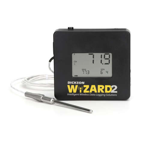
Dickson WiZARD2 User manual
Dickson
Dickson SK500 User manual
Dickson
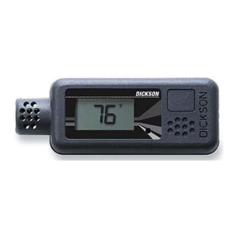
Dickson SR200 User manual
Dickson
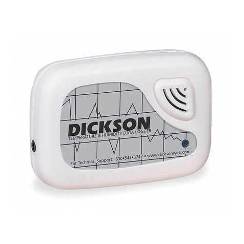
Dickson SP100 User manual

Dickson
Dickson SP125 User manual
Dickson
Dickson PR120 User manual
Dickson
Dickson HT100 User manual
Dickson
Dickson PR125 User manual
Dickson
Dickson SP125 User manual

