Diehl Hydrus User manual
English
HYDRUS
Ultrasonic Water Meter
Installation and user guide
1 2
5/8" x 3/4", 7 1/2" installation length,
20 GPM max. ow
3/4" S, 7 1/2" installation length,
30 GPM max. ow
3/4" L, 9" installation length,
30 GPM max. ow
1", 10
3/4"
installation length
55 GPM max. ow
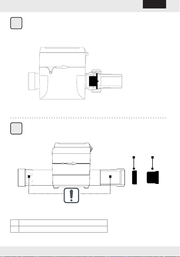
1Compensating ring
2Non-return valve
I
II
-2-
HYDRUS English

Contents
1. General information on the installation and user guide.. 4
2. General description ........................................................... 5
3. Use and operation.............................................................. 5
4. Guidelines for the HYDRUS ...............................................6
5. Transport and storage ....................................................... 6
6. Mounting / Installation .....................................................6
6.1 Installing the HYDRUS ........................................................... 7
6.2 Non-return valve ................................................................... 8
7. Communication.................................................................. 8
7.1 Optical interface .................................................................... 8
7.2 Encoder protocol ................................................................... 9
8. Operation .........................................................................10
8.1 Display / icons..................................................................... 12
8.2 Reporting date function (optional) ........................................ 12
9. Messages in the display...................................................13
9.1 Error messages ................................................................... 13
9.2 Alarm messages .................................................................. 13
10. Technical data..................................................................14
11. Error curves......................................................................15
12. Environmental notice ......................................................16
13. Certications....................................................................17
13.1 NSF International ................................................................ 17
-3-
HYDRUS
English
1. General information on the installation and user guide
Signs and symbols
To help use this guide quickly and safely.
Identies important information about how to use the HYDRUS
most eectively!
Identies important information warning against incorrect use
of and possible damage to the HYDRUS.
Target audience
This guide is intended for trained experts. For this reason, basic process
steps are not listed.
The HYDRUS should only be installed by trained meter installers.
Personnel must be trained in the handling of electrical equip-
ment as well as the AWWA M6 Manual "Water Meters Selection,
Installation, Testing, and Maintenance."
References
American Water Works Association (AWWA), M36 Manual, Water Au-
dits and Loss Control Programs Third Edition, 2009
AWWA, M6 Manual, Water Meters - Selection, Installation, Testing and
Maintenance Fifth Edition, 2012
-4-
HYDRUS English

2. General description
The HYDRUS is an electronic water meter designed to determine potable
water consumption.
The ultrasonic technology of the HYDRUS works reliably and yields precise
results even if exposed to dirty water and sand. Air in the pipe is not mea-
sured. This eliminates measurement errors and manipulations.
The UV-resistant housing and the completely encapsulated electronics
ensure a high durability and a long service life – even with high humidity,
ooded pits and pressure surges in the pipe system.
The HYDRUS is equipped with an optical interface and either a Nicor©,
ITRON© connector or wire end to read the data.
3. Use and operation
Intended use
The HYDRUS described here is used to measure the potable water con-
sumed in closed systems.
The HYDRUS may be used indoors or outdoors in accordance with the
technical specications (see "1. General information on the installation
and user guide" at page 4).
Non-compliant use
Any use other than that previously described or a modication to the de-
vice are considered non-compliant use. Such use or modication must be
requested in advance in writing and must be specially approved.
Do not use the HYDRUS as a tool or a lever.
Any manipulation or installation not performed properly or not in
accordance with the specications relieves the manufacturer of
all responsibility.
This is borne exclusively by the person responsible.
-5-
HYDRUS
English
4. Guidelines for the HYDRUS
Do not break the seal on the HYDRUS!.
A broken seal immediately voids the factory warranty.
IZAR@MOBILE2 software is used to read data and set parame-
ters. This software can be found at https://www2.diehl.com/
metering/en/diehl-metering/support-center/downloads.
5. Transport and storage
Water meters are precision devices! They must be protected
against impacts and vibration!
Make sure the meter is protected against frost when in storage
and during transport (the HYDRUS can be damaged by the ef-
fects of frost)!
6. Mounting / Installation
Install in accordance with the manufacturer's specications and/
or AWWA M6 standard.
Do not install ultrasonic meters near areas subject to a sudden
drop in pressure.
Install the HYDRUS only in waterpipe frostfree areas!
If there is danger of frost, drain the waterpipe and remove
HYDRUS if necessary.
Install using supplied ber washers in order to properly seal
connection to service line.
-6-
HYDRUS English

The HYDRUS operates in water temperatures between 34 °F
and 122 °F.
6.1 Installing the HYDRUS
Installation location
Maintain sucient distance between the HYDRUS and possible
sources of electromagnetic interference (switches, electric motors,
uorescent lamps, etc.).
Calming sections upstream and downstream of the HYDRUS are not
necessary.
Avoid a mounting position where air bubbles may accumulate in the
HYDRUS.
Preparations
If the water is dirty, install a dirt trap in the feed line upstream of
the HYDRUS.
Flush the pipes thoroughly before installing the HYDRUS.
Mounting
Close the shuto valves upstream and downstream of the water me-
ter or spacer and release the pressure in the pipeline.
Remove the spacer or old water meter.
Remove old washer, clean sealing faces and install ber gaskets.
Install the HYDRUS so that the arrow on the housing points with in
the direction of the water ow.
Install the HYDRUS in the pipeline, avoid mechanical stresses.
Protect the HYDRUS against pressure surges in the pipeline.
-7-
HYDRUS
English

Finishing tasks
Slowly open the shuto valves upstream and downstream of the
HYDRUS.
Check for possible leaks at the connections.
The HYDRUS must always be completely lled with water.
Failure to use provided ber gaskets or equivelant may result in
connection leaks and damage to the HYDRUS.
6.2 Non-return valve
If desired, the HYDRUS can be delivered with a non-return valve (accessory).
This valve must be installed in the discharge of the HYDRUS.
5/8
" x
3/4
'';
3/4
" S;
3/4
" L (see Fig. I, page 2) NSF certied
1" (see Fig. II, page 2) NSF certied
7. Communication
The HYDRUS has dierent communication interfaces:
Optical
Encoder
7.1 Optical interface
The HYDRUS can be congured by using the integrated optical interface.
IZAR@MOBILE2 software is used to read data and set parameters. This
software can be found at https://www2.diehl.com/metering/en/diehl-
metering/support-center/downloads.
If an error occurs during conguration, conguration must be started
again using the optical interface.
For correct conguration, place the opto head on the optical interface of
the HYDRUS.
We recommend the Bluetooth Opto Head IZAR OH BT for conguration.
-8-
HYDRUS English

7.2 Encoder protocol
Encoder is the standard communication protocol for connecting a radio
module, for example:
Pin assignment Nicor©connector *
V+ (red)
GROUND (black)
DATA (green)
Pin assignment Bare wire *
GROUND (brown)
V+ (white)
DATA (green)
* depending on variant
Pin assignment ITRON©sceam
-9-
HYDRUS
English
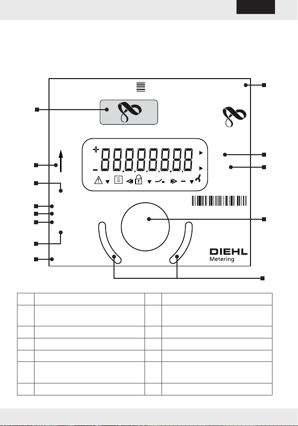
8. Operation
To read the HYDRUS from the display, various information (for example,
ow rate, volume, date, reporting date, water temperature) are available
consecutively by touching the optical pushbutton.
HYDRUS Made in Germany 11/20XX
Type 171
3/4“ S
Encoder
8D Standard
IP 68
3000123
gal.
gpm
1234 5648
.de
Flow
5
4
8
10
11
6
7
2
12
13
1
9
3
1 Part no. 8 Seal
2 Protection class 9 Country of manufacture /
Date
3 Digits 10 Unit
4 Interface 11 Flow rate
5 Nominal diameter 12 Optical pushbutton
6 Type 13 Positioning aid for the opto
head
7Flow direction
-10-
HYDRUS English

An optical pushbutton (see item 12) is positioned on the front panel of the
HYDRUS. By using the pushbutton the individual display loops are shown.
To save battery life, the display turns o if no control actions are taken for
4 minutes. By pressing the optical pushbutton the display becomes active
again and the current status appears in the display for about 2 seconds.
If there is a fault, an error message appears, E -- 7 -- A (air in the pipe),
for example.
Factory setting for the operating mode of the optical pushbut-
ton (short button press):
Error message
Total volume
Current ow
Temperature
High resolution reading
Software
Display test
The loop settings can be customized using the IZAR@MOBILE2
software.
Download the software from the Internet at https://www2.diehl.
com/metering/en/diehl-metering/support-center/downloads.
-11-
HYDRUS
English
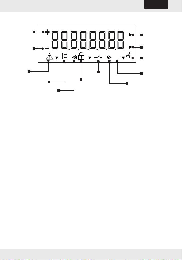
8.1 Display / icons
Forward
ow rate
Reverse
ow rate
Alarm /
fault
Reverse volume
Calibration value
Pushbutton
Reporting date Forward volume
Test mode
Flow rate
pointer
Service value
Water volume
pointer
8.2 Reporting date function (optional)
On the set reporting date, the consumption values to the next reporting
date are saved in memory. You can read them on the display or transfer
them via the encoder or the optical interface. You can program the re-
porting date as desired.
Factory setting = 12/31. Year of delivery.
-12-
HYDRUS English
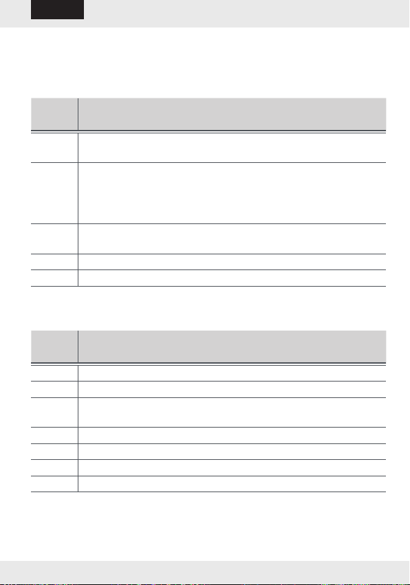
9. Messages in the display
9.1 Error messages
Visual indication on the LC display in the event of an error
Error
code
Description
C1 Basic parameters in the ash or RAM destroyed (replace the
HYDRUS).
E1 Faulty temperature measurement (temperature out of range,
sensor short, sensor open).
In the event of a sensor short or a sensor open, replace the
HYDRUS.
E4 Hardware fault, defective ultrasonic transducer or short circuit
ultrasonic transducer (replace the HYDRUS).
E5 Too frequent readout (no communication possible).
E7 No ultrasonic signal, air in the measurement section.
9.2 Alarm messages
Constant visual indication on the LC display in the event of an alarm
Alarm
code
Description
A1 Reverse ow
A3 No consumption
A4 Malfunction / failure of the ultrasonic or temperature measure-
ment
A5 Leakage alarm
A6 Low temperature (below 37 °F)
A7 Air in the measurement section, no volume measurement
A9 Low battery charge
-13-
HYDRUS
English
Combinations of fault and alarm messages may also occur, for
example, E17, corresponding to E1 and E7.
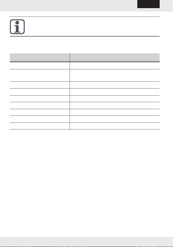
10. Technical data
Description Value
Water temperature range 34 to 122 °F
Ambient temperature
during operation
34 to 158 °F
Storage temperature range -4 to +158 °F (>90 °F max. 1 h)
Rated pressure 300 psi
Power supply 3.6 VDC lithium battery
Battery life Up to 20 years
Interfaces Industry Standard Encoder Protocol
Data storage For alarms and consumption values
Protection class IP 68
-14-
HYDRUS English
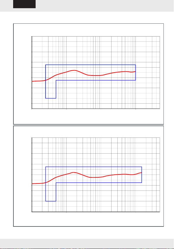
11. Error curves
-7
-6
-5
-4
-3
-2
-1
0
1
2
3
4
5
6
7
0222.020.0
Flow Rate in GPM
Deviation (%)
Typical Flow Chart 5/8"x 3/4" HYDRUS
-7
-6
-5
-4
-3
-2
-1
0
1
2
3
4
5
6
7
0222.020.0
Flow Rate in GPM
Deviation (%)
Typical Flow Chart 3/4" HYDRUS
-15-
HYDRUS
English

-7
-6
-5
-4
-3
-2
-1
0
1
2
3
4
5
6
7
0.02 0.2 2 20
Flow Rate in GPM
Deviation (%)
Typical Flow Chart 1" HYDRUS
12. Environmental notice
Dispose of the HYDRUS in an environmentally friendly way, take it to a
local recycling center after use.
-16-
HYDRUS English
13. Certications
13.1 NSF International
-17-
HYDRUS
English


Other manuals for Hydrus
1
Table of contents
Other Diehl Measuring Instrument manuals

Diehl
Diehl RAY FS WP User manual

Diehl
Diehl SHARKY 774 Installation instructions

Diehl
Diehl IZAR PULSE i User manual

Diehl
Diehl Hydrus 171A User manual

Diehl
Diehl Scylar 548 User manual

Diehl
Diehl SHARKY 774 COMPACT User manual

Diehl
Diehl IZAR Pulse H User manual

Diehl
Diehl AQUARIUS S User manual

Diehl
Diehl SHARKY 774 User manual

Diehl
Diehl SHARKY 775 User manual


