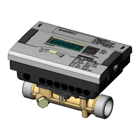
Diehl SHARKY 774 COMPACT User manual

Ultrasonic energy meter
Contatore di energia ad
ultra suoni
Ultralydsenergimålere
Ultraljuds-energimätare
Installation guide
Istruzioni per il montaggio
Installationsvejledning
Monteringsanvisning
English Italiano Dansk Svenska
This guide must
be given to the end
consumer. Consegnare
queste istruzioni al cliente
nale. Denne vejledning
skal aeveres til montøren.
Denna bruksanvisning
ska överlämnas till
kunden.

-2-
English Italiano Dansk Svenska
III
I
II
IV
2
1
4
3
5
A
B
A
B
A
B

-3-
English Italiano Dansk Svenska
V
A B C
ED
VI
A B

-4-
English Italiano Dansk Svenska
Table of content
1. General ...............................................................................5
1.1 Operating conditions ................................................................ 6
2. Transport and storage........................................................6
3. Assembly / installation ......................................................7
3.1 Preparatory work ..................................................................... 7
3.2 Installing the ow sensor.......................................................... 8
3.3 Fitting the temperature sensor pair ........................................... 9
3.3.1 Installation in the ball valve with adapter................................... 9
3.3.2 Installation in a pocket........................................................... 10
3.4 Installing the integrator.......................................................... 10
3.5 Functional testing .................................................................. 10
4. Communication ................................................................11
4.1 M-Bus wired (optional)........................................................... 11
4.2 M-Bus wireless radio (optional) ............................................... 12
5. Display / Operation ..........................................................13
5.1 Display.................................................................................. 13
5.2 Push button........................................................................... 13
5.3 Display loops ......................................................................... 14
6. Error messages.................................................................17
7. Maintenance.....................................................................18
8. Disposal............................................................................18
9. Declaration of conformity for MID meters.......................18
9.1 DMDE-CE 161/5..................................................................... 59
9.2 DMDE-CE 172........................................................................ 61
9.3 DMDE-NEV 417...................................................................... 62

-5-
English Italiano Dansk Svenska
1. General
This guide is intended for trained specialised personnel. For this reason no
basic working steps are included.
The meter tamper-evident seal must not be damaged!
A damaged seal will result in immediate invalidation of the factory
warranty and verication or declaration of conformity. The cables
supplied with the meter must neither be shortened, extended
nor changed in any other way.
The regulations on the use of energy meters must be observed!
The installation must only be carried out by a specialist company.
The personnel must be trained in the installation and handling of
electrical equipment.
Medium
Water according to AGFW-Worksheet FW510 (the lifecycle of the
meter may be impaired if not observed).
The temperature range depends on variant and nominal size.
Detailed user guide available at http://www.diehl.com/en/diehl-metering/
products-solutions/product-download/.
This user guide must be observed without fail.
The IZAR@SET software is used for readout/parametrization and is
available online at http://www.diehl.com/en/diehl-metering/products-
solutions/product-download/.
Please select the partner "Diehl Metering GmbH" and the product area "
Metering Systems".

-6-
English Italiano Dansk Svenska
1.1 Operating conditions
The temperature conditions for the ow sensor and the tempera-
ture sensor depend on the application and can be found on the
printing of the meter.
Climatic conditions
The ambient temperature must be between 5…55 °C.
Temperatures > 35 °C have a positive effect on battery lifetime.
2. Transport and storage
Unpacking
Energy meter are measuring devices and must be handled with care. To
protect against damage and soiling, they should only be unpacked imme-
diately prior to installation.
Transport
The transport of the meter is permitted only in the original package.
When sending wireless measuring instruments / components by
air, deactivate the wireless before shipping.
Storage
The meter must only be stored in a dry location.
Typical storage temperature +5 °C ... 55 °C
Maximum storage temperature -20 °C ... 60 °C (dry, duration up to
4 weeks)
Relative humid environment < 93 %

-7-
English Italiano Dansk Svenska
3. Assembly / installation
The meter may only be installed in frost-free spaces. Be careful
of sharp edges.
Assembly and disassembly only in depressurised system.
The meter is to be protected against damages due to impacts
and vibrations.
The pipelines are to be attached before and behind the meter.
Pipes for measuring signals are to be installed far away from
other power lines.
When choosing the installation location, make sure that the
meter is perfectly accessible for service and operating personnel.
It is recommended that shut-off valves are tted before and after
the meter to simplify removing the meter.
3.1 Preparatory work
1. Rinse the conduit thoroughly.
2. Close the stop valves upstream and downstream of the meter and
depressurise the pipeline.
It is recommended to install a dirt trap in front of the ow sensor
or at another suitable position of the circulation.
No inlet or outlet path is necessary for the installation of a ow
sensor.
With heating systems without temperature mixing or temperature strati-
cation, the pre-connection of a feeding length of 3-10 DN in front of the
meter is recommended.

-8-
English Italiano Dansk Svenska
3.2 Installing the ow sensor
During heat application, Twater > Tambient must be permanent.
During cold application or with Twater < Tambient variant cooling
meter is to be used.
Mounting position / Position
The meter can be installed in both horizontal and vertical pipe sec-
tions (see g. I).
We recommend installing the ow sensor in a tilted position, to trans-
port possible air bubbles from the circulation(see g. II).
Install the ow sensor so that the ow direction matches the arrow
direction on the sensor (see g. III).
Depending on the version, the ow sensor must be installed in ow
or return. The installation position is displayed in the info loop 3.4
(see "Information loop (3)" at page 15) and also by means of a
pictogram.
Flow Return
Please make sure that the ow sensor is always lled with water.
The meter measures only the energy of completely lled pipe-
lines. Otherwise a corresponding error message is shown in the
display.
The minimum system pressure to avoid cavitation is 1 bar.

-9-
English Italiano Dansk Svenska
3.3 Fitting the temperature sensor pair
The meter is only sold with separately approved temperature
sensor pairs of type Pt 500.
Handle the temperature sensor carefully!
The sensor cables are provided with coloured type plates:
Red: sensor in the hot line
Blue: sensor in the cold line
The connecting lines of the temperature sensors, may not be
shortened or extended.
A common routing in cable conduits or on cable racks with power
supply lines are not admissible.
The minimum distance for low voltage cables according to EN 1434 - 6 of
50 mm must be observed.
3.3.1 Installation in the ball valve with adapter
(coupling set in a separate bag)
Use ball valves with installation option for temperature sensor with thread
M10 x 1.
Preparatory measures
Close the ball valve.
Unscrew the plug screw from the ball valve.
Installation (see g. IV)
1. Place the O-ring from the attached coupling set (type A or B) on the
mounting pin.
2. Insert the O-ring with the mounting pin into the sensor hole of the ball
valve (turn the mounting pin).
3. Position the O-ring in its nal position using the other end of the
mounting pin.
4. Fastening screws
Type A (plastic) - put the fastening screw onto the temperature sen-
sor.

-10-
English Italiano Dansk Svenska
Type B (brass) - slide the fastening screw onto the temperature sen-
sor and attach the fastening screw with the dowel pin. Press in the
dowel pin completely and remove the mounting pin from the tem-
perature sensor.
5. Insert the temperature sensor with adapter tting into the ball valve
and tighten fastening screw by hand (2-3 Nm).
3.3.2 Installation in a pocket
In case of new installations, temperature sensors for nominal sizes DN25
or smaller should only be installed immersed.
This ensures higher measuring accuracy.
3.4 Installing the integrator
Pay attention to sufcient distance between integrator and pos-
sible electromagnetic sources of interference (switches, electric
motors, uorescent lamp, etc.) during installation.
For medium temperatures from 90 °C or for TWater < TAmbient (cooling
meter application) the integrator must be removed and tted at a suf-
cient distance from any heat/cold sources. The adapters VI A or VI B are
available.
3.5 Functional testing
After installation of the meter, putting into operation and functional test-
ing can be performed.
Proceed as follows:
Open the stop valves
Check system for tightness
Bleed the system till the ow indication is stable. Adjust the system by
means of the ow indication
After a short while the message "E-7" disappears in the display.
Press the push button next to the display and check the displays for
temperature and ow for plausibility.
Attach tampering protection at the integrator and the temperature
sensors.
Read and note meter data for energy, volume and serial number.

-11-
English Italiano Dansk Svenska
Error messages when assembly is wrong
Error code Description
E - 3 Temperature sensors were mixed up during installation or
connection.
E - 6 Meter were installed against the planned ow direction.
During system downtime the error messages "E - 3" and "E - 6"
may appear without possible wrong assembly inside.
4. Communication
4.1 M-Bus wired (optional)
A 2 pin M-Bus line lead out of the housing.
Connect the M-Bus line with the marked connections of the
M-Bus Master.
Here it concerns a serial interface for communication with external devices
(M-Bus control centres), e.g. IZAR CENTER.
Standardised according to EN 13757-3
Galvanic isolation
Polarity reversal protection
Power consumption: One M-Bus load
Primary or secondary addressing
Baud rate 300 or 2400 baud (automatic baud rate detection)
Protocol: M-Bus
Reading interval: every 3 minutes *
* the meter detects, if the reading is done more often than every 3 min-
utes. The meter stopped sending responses and conrms with the error
code E-5 (too frequent read-out via M-Bus). The error is automatically
deleted after a variable break time and communication is then possible
again.

-12-
English Italiano Dansk Svenska
4.2 M-Bus wireless radio (optional)
The integrated radio module is an interface for communication of proto-
cols with Diehl Metering radio receivers. The communication protocol is
preset.
Note on radio function
The radio function is switched off on delivery and activated auto-
matically when water is detected in the meter. The radio function
remains permanently active after a period of continuous opera-
tion (>3 hours) with water.
The integrated radio interface is specied with:
Unidirectional transmitting direction
Data timeliness: Online - no time delay between data logging and
data communication
The integrated radio accesses always the actual meter readings
Transmission frequency: 868 MHz
Various Diehl Metering receivers are available for receiving the proto-
col (e.g. Bluetooth, GPRS, LAN, …)
Encrypted protocol: Open Metering Standard
Reading modes: Walk-By, Drive-By, Fixed-Network

-13-
English Italiano Dansk Svenska
5. Display / Operation
5.1 Display
The visualization at the meter is done via a 8 digit LCD with unit and
symbol display.
5.2 Push button
A push button is mounted on the front plate of the meter. This push but-
ton is used to switch to the various displays.
Action Function
Briey press the key
(<3 seconds) Switch within one loop
Hold the key
(> 3 seconds) Switch to the next display loop
Do not press the key for
4 minutes Meter turns off the display automatically
(energy saving, only if no error prevails)
Press the key again The meter is in the basic display
Flow indicator
Maximum values
Identication for
calibrated value
Display of the
quadrant
Loop display
Error symbol

-14-
English Italiano Dansk Svenska
5.3 Display loops
The data read by the integrator can be viewed in several displays. These
displays contain the assigned system information (e.g. accumulated
energy, accumulated volume, ow, power, actual temperatures, ...) and
can be accessed by calling the displays in the pre-dened sequence / loop.
The display content of each loop is programmed at factory with standard
information.
Various display windows consist of up to seven value displays alternating
in the 2 - 4 s rhythm.
The display is updated every 2s, since an internal calculation takes place
every 2s.
Main loop (1)
Sequence Window 1 Window 2
1.1 Accumulated energy
1.2 Accumulated volume
1.3 Accumulated cold energy
(heat meters with cooling
tariff)
1.4 Flow
1.5 Power
1.6 Flow temperature
Return ow temperature *)
Return ow temperature **)
1.7 Differential temperature
1.8 Operating days
1.9 Error status Error hours
1.10 Display test
*) without a decimal place; **) with one decimal place respectively
Code of the loop

-15-
English Italiano Dansk Svenska
The basic display shows the display "energy", if the meter is integrated
into the pipeline, the pipeline is lled completely with water and no error
prevails (sequence 1.1).
As soon as an error occurs, it is permanently shown in the basic
display. The meter will not enter the power saving mode. If the
cause of the error is eliminated, the error in the display disap-
pears.
Due date loop (2)
Sequence Window 1 Window 2 Window 3
2.1 Due date 1 date Due date 1
energy "Accd 1A"
2.2 "Accd 1" Date of future due
date 1
2.3 Due date 1 previ-
ous year Date due date
1 previous year
energy
"Accd 1L"
2.4 Due date 2 date Due date 2
energy "Accd 2A"
2.5 "Accd 2" Date of future due
date 2
2.6 Due date 2 previ-
ous year date Due date 2 previ-
ous year energy "Accd 2L"
Information loop (3)
Sequence Window 1 Window 2
3.1 Actual date
3.2 "SEC_Adr" Secondary address
3.3 "PRI_Adr 1" Primary address
3.4 Installation location
3.5 Software version Check sum

-16-
English Italiano Dansk Svenska
Month loop (6) (heat- or cooling meter)
Sequence Window 1 Window 2 Window 3 Window 4
6.1 "LOG" Date last
month Energy Volume
6.2 "LOG" Date
-1 Energy Volume
:::::
6.24 "LOG" Date
-23 Energy Volume
Month loop (6) (heat meters with cooling tariff)
Sequence Window 1 Window 2 Window 3 Window 4 Window 5
6.1 "LOG" Date last
month Heat
energy Cold
energy Volume
6.2 "LOG" Date
-1 Heat
energy Cold
energy Volume
: : : : : :
6.24 "LOG" Date
-23 Heat
energy Cold
energy Volume

-17-
English Italiano Dansk Svenska
6. Error messages
The meter constantly performs self-diagnostics and can display
various error messages. If an error occurs, the error code is dis-
played in the main loop.
All windows, however, can still be accessed by pressing the key.
The error message disappears automatically as soon as the source of the
error is corrected. All errors that occur for longer than 6 minutes without
interruption, are saved in the error memory.
Error
code
Description
C - 1 Basic parameter error in ash or RAM - Meter must be
replaced
E - 1 Erroneous temperature measurement
Temperature range exceeds [-19.9 °C...190 °C]
Sensor short circuit
Sensor break
E - 3** Temperature sensor mixed up in hot and cold line
E - 4 Hardware error during ultrasonic measuring
Ultrasonic transducer defective
Short-circuit ultrasonic transducer
E - 5 too frequent reading
no M-Bus communication possible for a short time
E - 6** ow direction incorrect
Installation of ow sensor wrong
E - 7 No reasonable ultrasonic receive signal
Air in the measuring path
E - 9 Warning: Running out of battery capacity
** application dependent

-18-
English Italiano Dansk Svenska
7. Maintenance
Flow sensor and temperature sensor may not be connected from
the integrator.
After repair work, perform recalibration in an accredited testing
agency.
Information concerning reconditioning or maintenance can be
found in the processing concept (this will be made available for
laboratories and testing agencies upon request).
8. Disposal
The meter contains a lithium battery, which is not rechargeable.
Do not use force to open the battery. It must never come into
contact with water, short-circuited or exposed to temperatures
over 75 °C.
Empty batteries and no longer required electronic devices or components
are hazardous waste.
This device must not be disposed together with the domestic waste.
Return it to the manufacturer for recycling.
9. Declaration of conformity for MID meters
See from page 65 onwards.
Further information as well as the actual declaration of conformity are
available at:
http://www.diehl.com/en/diehl-metering/products-solutions/product-
download/
Please select the partner "Diehl Metering GmbH" and the product area
"Thermal Energy Metering".

-19-
English Italiano Dansk Svenska
Sommario
1. Informazioni generali.......................................................20
1.1 Condizioni d'esercizio ............................................................. 20
2. Trasporto e stoccaggio.....................................................21
3. Montaggio/Installazione..................................................21
3.1 Lavori preliminari ................................................................... 22
3.2 Montaggio del sensore di usso .............................................. 22
3.3 Montaggio della coppia di sensori di temperatura ..................... 23
3.3.1 Montaggio in valvola a sfera con adattatore ............................. 23
3.3.2 Montaggio in pozzetto a immersione ....................................... 24
3.4 Montaggio del calcolatore....................................................... 24
3.5 Controllo del funzionamento ................................................... 24
4. Comunicazione .................................................................25
4.1 M-Bus a lo (optional)............................................................ 25
4.2 Radio M-Bus senza li (optional) ............................................. 26
5. Visualizzazione/Funzionamento ......................................27
5.1 Display.................................................................................. 27
5.2 Pulsante................................................................................ 27
5.3 Cicli di visualizzazione............................................................. 28
6. Messaggi di errore............................................................31
7. Manutenzione...................................................................32
8. Nota sulla tutela ambientale............................................32
9. Dichiarazione di conformità degli apparecchi alla
Direttiva MID....................................................................32
9.1 DMDE-CE 161/5..................................................................... 59
9.2 DMDE-CE 172........................................................................ 61
9.3 DMDE-NEV 417...................................................................... 62

-20-
English Italiano Dansk Svenska
1. Informazioni generali
Queste istruzioni sono rivolte a personale specializzato e adeguatamente
formato. Pertanto i passaggi fondamentali dei lavori non sono descritti.
La piombatura del contatore non deve essere rotta.
La rottura della piombatura ha come conseguenza l'immediato
annullamento della garanzia di fabbrica, della taratura e della
Dichiarazione di conformità. È fatto divieto di accorciare, allun-
gare o altrimenti modicare i cavi forniti in dotazione.
Rispettare le disposizioni per l’impiego dei contatori di energia!
L'installazione deve essere effettuata solo da una ditta di instal-
lazione specializzata. Il personale deve essere opportunamente
addestrato all’installazione e all’uso di apparecchi elettrici.
Mezzo
Acqua secondo le istruzioni FW510 dell’AGFW (l’eventuale inos-
servanza può pregiudicare la durata del contatore).
L’intervallo di temperatura dipende dalla versione e dalla grandezza nominale.
Le istruzioni per l’uso complete con ulteriori dettagli sulle possibili versioni
sono disponibili alla pagina http://www.diehl.com/en/diehl-metering/
products-solutions/product-download/.
È indispensabile attenersi alle presenti istruzioni per l'uso.
Per la lettura/parametrizzazione serve il software IZAR@SET scaricabile
alla pagina http://www.diehl.com/en/diehl-metering/products-solutions/
product-download/.
Selezionare il partner "Diehl Metering GmbH" e l'area prodotti "Metering
Systems".
1.1 Condizioni d'esercizio
Le condizioni di temperatura per il sensore di usso e il sensore
di temperatura dipendono dall'applicazione e sono riportate nei
dati impressi sul contatore.
Ambiente climatico
La temperatura ambiente deve essere compresa nell'intervallo 5…55 °C.
Temperature < 35 °C favoriscono la durata di vita della batteria.
Table of contents
Languages:
Other Diehl Measuring Instrument manuals
Diehl
Diehl Hydrus User manual

Diehl
Diehl RAY FS WP User manual

Diehl
Diehl Hydrus 171A User manual
Diehl
Diehl AQUARIUS S User manual
Diehl
Diehl SHARKY 774 User manual

Diehl
Diehl Hydrus User manual
Diehl
Diehl SHARKY 774 Installation instructions
Diehl
Diehl Scylar 548 User manual
Diehl
Diehl IZAR Pulse H User manual
Diehl
Diehl Elicius User manual
