Diesse VES MATIC 5 User manual
USER MANUAL
Rev. 2.2 –May 2022
Bench top analyser for automated determination
of the erythrocyte sedimentation rate (ESR)
SOFTWARE VERSION 1.xx.xx
VES MATIC 5 (REF. 10360)
ONLY FOR IN VITRO DIAGNOSTIC USE


Rev. 2.2 (05.2022)
VES MATIC 5 | USER MANUAL
1
This page is intentionally left blank.

2
VES MATIC 5 | USER MANUAL
Rev. 2.2 (05.2022)
VES MATIC 5 models:
This manual applies to the following models of VES MATIC 5.
Catalogue number
Description
10360
VES MATIC 5
Accessories:
Catalogue number
Description
10293
TEST DEVICE NEXT 500 (500 tests)
10294
TEST DEVICE NEXT 1K (1000 tests)
10296
TEST DEVICE NEXT 5K (5000 tests)
10297
TEST DEVICE NEXT 10K (10000 tests)
10403
Thermal paper
10435
ESR Control Cube (4 x 9 mL)
List of manual revisions
Manual revision
Description of changes
1.0 –12/2020
First issue
2.0 –06/2021
Correction to chapter 3 “INSTRUMENT PREPARATION”. In-depth
study of chapter 4 “USE OF THE INSTRUMENT”. Update of images
and figures.
2.1 –11/2021
Update of compliance with applied standards and operational
features.
2.2 –05/2022
Update of the intended purpose

Rev. 2.2 (05.2022)
VES MATIC 5 | USER MANUAL
3
MANUFACTURER
DIESSE DIAGNOSTICA SENESE SPA
Strada dei Laghi 39, 53035 Monteriggioni (SI) Italy
Phone +39 0577 307109, Fax. + 39 0577 307106
www.diesse.it
TECHNICAL ASSISTANCE
Strada dei Laghi 39, 53035 Monteriggioni (SI) Italy
Phone +39 0577 307109, Fax. + 39 0577 307106
Toll-free number: 800 606932
email: technicalsuppo[email protected]
If any serious incident in relation to this device has occurred in the European Union
market territory, please report without delay to the manufacturer and competent
authority of your Member State.
No part of this manual may be reproduced in any form or by any means, electronic,
mechanical or otherwise, for any use whatsoever without the prior written permission
of DIESSE Diagnostica Senese S.p.A.
4
VES MATIC 5 | USER MANUAL
Rev. 2.2 (05.2022)
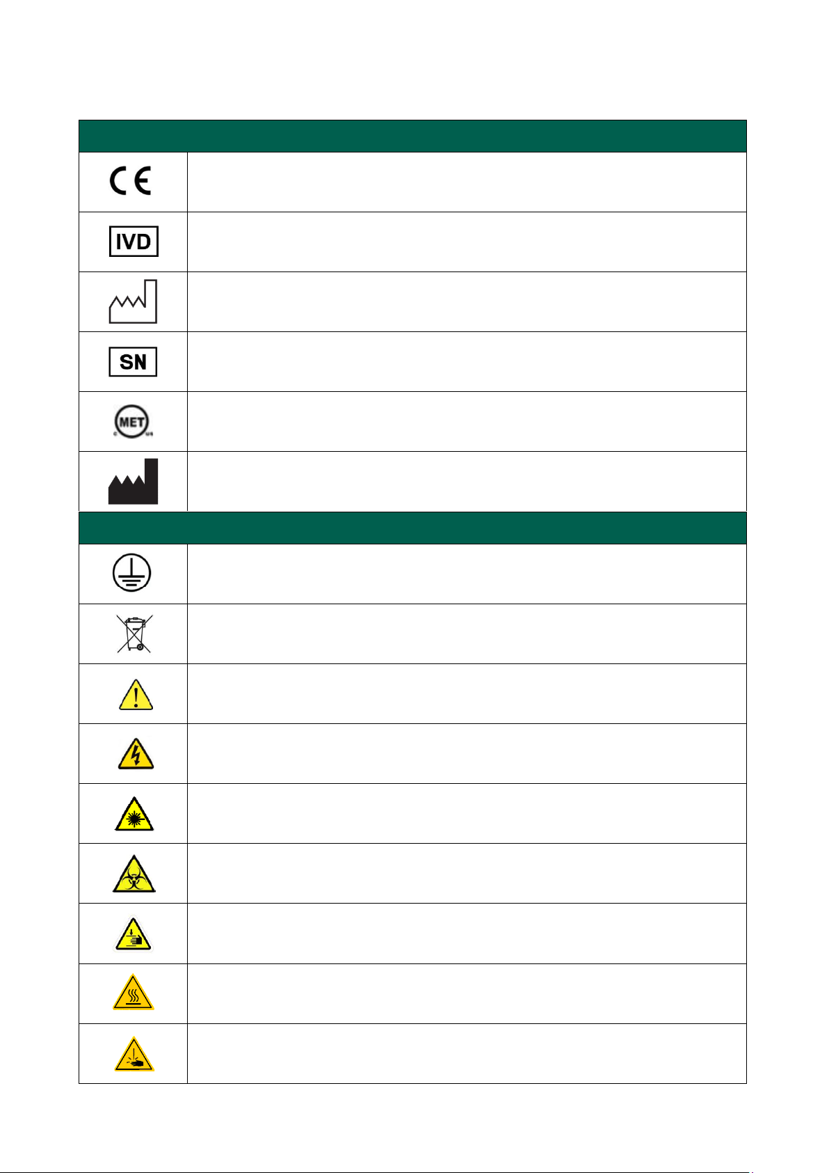
Symbols:
Legend of graphic symbols used in this manual
Instrument meeting the requirements of the EC Directive 98/79 on in
vitro diagnostic medical devices.
In vitro
diagnostic medical device
Date of manufacture of the device
Serial number of the device
Device compliant with the MET standards for the Canadian and US
market.
Manufacturer's Data
Legend of electrical and safety symbols used in this manual
Protective conductor
WEEE: Electrical-Electronic Equipment - Separate waste collection
obligation pursuant to L. Decree no. 49 dated 14/03/2014 (Italy),
implementing Directive 2012/19/EC
Attention, read the manual, follow the safety symbols.
Warning, danger of electric shock
Warning: laser beam
BIOHAZARD: risk of contamination with potentially infected
substances.
Risk of hand crushing due to mechanical movements
Risk of thermal shock due to heating of the sample plate
Risk of puncture due to the presence of needles for collection and
dispensing

Rev. 2.2 (05.2022)
VES MATIC 5 | USER MANUAL
5
General warnings
Before installation and use of the instrument, for proper and safe use, it is advisable to
carefully read the warnings and instructions in this user manual. It is important that
this instruction manual should be kept together with the instrument for future
reference. In case of sale or transfer, make sure that this manual accompanies the Ves-
Matic 5 to allow new users to be informed about the instrument’s operation and the
related warnings.
It is recommended to allow only qualified and skilled personnel to use the instrument.
The installation must be carried out by an installation technician authorised by Diesse
Diagnostica Senese S.p.A. as stated in the Installation Report provided separately with
the Installation Guide
6
VES MATIC 5 | USER MANUAL
Rev. 2.2 (05.2022)
LIMITATIONS AND WARNINGS
The VES-MATIC 5 instrument is designed to be used exclusively with the procedures
established by DIESSE Diagnostica Senese S.p.A., stored in the internal memory of the
instrument and with the components manufactured and supplied by DIESSE itself.
Any use that differs from the indications provided by the manufacturer may lead to an
increased risk of measurement error, for which the user is fully responsible.
Any violation of the software protections and any tampering with the planned analysis
procedures in the internal memory of the instrument will void any warranty for the
instrument.
For technical assistance, contact the service centre in your country or the DIESSE
technical service centre.
WARNING
Do not use this manual unless complete.
If used in an incomplete form, DIESSE Diagnostica Senese S.p.A. declines all
responsibility in the event of adverse results.
WARNING
The screenshots in this manual are for illustration purposes only.
DIESSE is not liable for damages caused directly or indirectly by errors, faults or incidents,
due to the use of manuals that do not correspond to the version of the instrument
provided.
Rev. 2.2 (05.2022)
VES MATIC 5 | USER MANUAL
7
BIO-CONTAMINATION HAZARDS
Potentially infected material is handled.
When a system like the VES-MATIC 5 is used, all precautions must be
taken regarding biological risks.
The samples must be disposed of in accordance with laboratory
instructions and with local laws.
Observe personal and group safety measures required for the
operator and appropriate for the work environment. Comply with
directives on safety and with applicable laws in force.
In the case of leakage of biological material, during the working
cycle, clean external surfaces of the instrument using appropriate
personal protective equipment and observe regulations on
sanitisation.
All supplied materials must be disposed of in accordance with local
laws.

8
VES MATIC 5 | USER MANUAL
Rev. 2.2 (05.2022)
Contents:
1INTRODUCTION......................................................................................................................................................................................10
1.1 Intended PURPOSE........................................................................................................................................................................10
1.2 General information.......................................................................................................................................................................10
1.3 Presentation of the instrument..............................................................................................................................................10
1.4 Description of the instrument ...........................................................................................................................................12
1.4.1 Front side ...............................................................................................................................................................................................13
1.4.2 Back side.................................................................................................................................................................................................14
1.4.3 Right side...............................................................................................................................................................................................15
1.5 Ves-Matic 5 models.........................................................................................................................................................................16
1.6 Compatibility with lavender top tubes ........................................................................................................................17
1.7 Technical data ....................................................................................................................................................................................18
1.8 Technical description of the instrument.....................................................................................................................19
1.9 Disposal .............................................................................................................................................................................................21
2TRANSPORT, INSTALLATION AND WARNINGS...............................................................................................................23
2.1 Transport...............................................................................................................................................................................................23
2.2 Preparation and checks before installation.............................................................................................................23
2.3 Positioning .....................................................................................................................................................................................24
2.4 UNPACKING..................................................................................................................................................................................25
2.5 REMOVING LOCKS AND PREPARATION..................................................................................................................28
2.6 Commissioning the instrument......................................................................................................................................30
2.6.1 Personal protection equipment (PPE)..........................................................................................................................30
2.6.2 Instrument label...............................................................................................................................................................................31
2.6.3 Emergency Shutdown Switch.............................................................................................................................................. 31
2.7 Uninstallation and Reinstallation.....................................................................................................................................31
2.7.1 Positioning in the same building or room.................................................................................................................. 31
2.7.2 Placement in a different location......................................................................................................................................32
2.7.3 Uninstalling the instrument..................................................................................................................................................32
2.8 Cleaning and Maintenance ................................................................................................................................................32
2.8.1 Cleaning.................................................................................................................................................................................................32
2.9 Maintenance.................................................................................................................................................................................33
2.9.1 Routine maintenance.................................................................................................................................................................33
2.9.2 Scheduled maintenance..........................................................................................................................................................34
2.10 Replacements..............................................................................................................................................................................34
2.10.1 Printer paper replacement...............................................................................................................................................34
2.10.2 Fuse replacement....................................................................................................................................................................35
2.11 Limitations and Warnings...................................................................................................................................................37
3INSTRUMENT PREPARATION......................................................................................................................................................39
3.1 Switching on the instrument..................................................................................................................................................39

Rev. 2.2 (05.2022)
VES MATIC 5 | USER MANUAL
9
3.2 Description of the system....................................................................................................................................................39
3.2.1 Main menu...........................................................................................................................................................................................39
3.3 Check device................................................................................................................................................................................ 48
3.4 Guided reading of the results printout ...................................................................................................................... 48
4USE OF THE INSTRUMENT.............................................................................................................................................................53
4.1 General description of an analytical cycle.................................................................................................................53
4.2 Detailed Description................................................................................................................................................................53
4.2.1 Sample preparation......................................................................................................................................................................53
4.2.2 Warnings and limitations ........................................................................................................................................................56
4.2.3 Preparation for work cycle and authentication.....................................................................................................56
4.2.4 Sample Loading.............................................................................................................................................................................. 60
4.2.5 Starting an Analysis Cycle........................................................................................................................................................62
4.2.6 Analysis abort: "STOP" button...................................................................................................................................................68
4.2.7 End of the analytical cycle........................................................................................................................................................71
4.2.8 Coloured front bar...........................................................................................................................................................................71
4.2.9 Conclusion of daily analytical activity...................................................................................................................................71
4.3 ARCHIVE...................................................................................................................................................................................................72
4.3.1 Archive fields.............................................................................................................................................................................................73
4.3.2 Possible operations from the archive..................................................................................................................................74
4.4 SETTINGS.................................................................................................................................................................................................79
4.4.1 Language, Temperature Scale, Date/Time......................................................................................................................79
4.4.2 Print Results, Custom Header, User Management .................................................................................................82
4.4.3 QC Diesse, QC decoding .............................................................................................................................................................. 88
4.4.4 Export Log, Archive Management, Recharge..............................................................................................................91
4.4.5 Support service.....................................................................................................................................................................................92
5TROUBLESHOOTING.........................................................................................................................................................................95
5.1 Troubleshooting...............................................................................................................................................................................95
BIBLIOGRAPHY.................................................................................................................................................................................................97
Annex A: MANUAL METHOD ACCORDING TO WESTERGREN TECHNIQUE............................................98

10
VES MATIC 5 | USER MANUAL
Rev. 2.2 (05.2022)
1INTRODUCTION
1.1 INTENDED PURPOSE
The Ves-Matic 5 is an automated instrument for the quantitative Erythrocyte
Sedimentation Rate (ESR) determination, measured using modified Westergren
method on venous whole blood anticoagulated with EDTA.
ESR is a non-specific parameter of an inflammatory status, used as an aid for the
monitoring of the physiological or pathological state of the patient.
The instrument is to be used only by professional laboratory users.
1.2 GENERAL INFORMATION
Before using the instrument, you must carefully read and follow all
the safety features underlined in section 2 (Safety) and be aware of the measures
necessary to prevent the potential risks associated with the use of the Ves-Matic 5
instrument.
1.3 PRESENTATION OF THE INSTRUMENT
The erythrocyte sedimentation level in autologous plasma is read directly into the
lavender top tubes, thanks to an innovative optoelectronic system, so that no dedicated
sample of citrate blood is required for the test. The system fits well into the laboratory
workflow, since the samples, contained in the blood cell count racks used in the
laboratory, are continuously loaded and with random access, without interruptions or
stops in each machine work phase. The selection of ESR samples from non-ESR samples
takes place automatically, thanks to the connection of the instrument to the computer
system of the laboratory, through the "Host query".
The analysis is carried out completely automatically (mixing and reading of the sample)
and the results, obtained in only 20 minutes, are comparable to those obtained with the
1- hour Westergren Reference method (Bibl. ref. 1-10). The maximum analytical capacity
of the system is 190 results/hour.
Since the analysis is performed without having to collect the sample from the primary
tube, the instrument does not produce any waste liquid to be decontaminated, thus
ensuring complete safety for the operator and economic savings in the disposal of
hospital waste.
The instrument is designed with the temperature correction always activated and
relates the results to a temperature of 18°C according to Manley’s Nomogram (graph 1.1).
However, it is possible to de-select the temperature correction for individual laboratory
needs.

Rev. 2.2 (05.2022)
VES MATIC 5 | USER MANUAL
11
Graph 1 - Manley’s Nomogram
.
Clinical meaning of ESR
The ESR (erythrocyte sedimentation rate) analysis consists in measuring the distance
travelled by the red blood cells when separating from the autologous anticoagulated
plasma over a predetermined period of time. In normal conditions, red blood cells tend
to reject each other due to the negative net charge of their cell membrane, caused by
the presence of numerous residues of sialic acid at the membrane glycoprotein level.
When the plasma protein composition changes following an inflammatory process or
tissue damage, with the production of the so-called “acute phase proteins” thanks to the
binding of these proteins (fibrinogen, immunoglobulins) to the erythrocyte surface, the
negative charge of the membrane (Zeta potential) is altered and the red blood cells can
stack, to form the so-called rouleaux, which then aggregate to form microspheres of
uniform radius, which begin to sediment when their density exceeds that of the plasma
in which they are immersed. The ESR value is therefore increased in all those situations
where there is an increase in acute phase proteins and in particular of fibrinogen (which
is thought to contribute 70% to the total sedimentation phenomenon) and
immunoglobulins (which can be high in case of haematology-oncology diseases). ESR
therefore represents an indirect and non-specific measure of an inflammatory state and
is increased in various pathological situations such as inflammatory diseases (infections,
rheumatic diseases), relative/absolute increase in globulins (nephrotic syndrome,
myelomas), tissue necrosis (myocardial infarction, tumours). ESR is useful in predicting
the prognosis of certain diseases such as polymyalgia rheumatic arthritis, giant cell
arteritis, rheumatoid arthritis and Hodgkin's disease and is useful as a marker of
treatment effectiveness in many diseases such as rheumatoid arthritis, vasculitis,
collagenosis, septic arthritis.
ESR is normally higher in women than in men and it also increases during pregnancy;
there is also a tendency for ESR to increase in both sexes as the age increases.
In the classic formulation of Westergren, the test is performed on blood anticoagulated
with citrate, in the proportion of 4 parts of blood and one part of anticoagulant. The blood
thus treated is aspirated into a special graduated pipette with an internal diameter of 2.5
mm kept vertically in a stand and the sedimentation level of the red blood cells is
recorded after one hour, measuring the distance between the lower side of the plasma
meniscus and the upper side of the layer of the deposited red blood cells. In the Ves-
Matic 5 system, the erythrocyte sedimentation results in anticoagulated plasma with
EDTA are reprocessed using the formula given in the document (insert quote) to
transform them into sedimentation values in a citrate solution, in order to provide ESR
results in total agreement with international guidelines.

12
VES MATIC 5 | USER MANUAL
Rev. 2.2 (05.2022)
General functioning of the instrument:
The blood collected in the test tubes for the CBC (cell blood count) test is carefully mixed
by the instrument, and the samples then remain at rest for a predetermined amount of
time to allow sedimentation to occur.
Through analogue sensors (optoelectronic units), the instrument automatically
determines the erythrocyte level at time zero and after 20 minutes of sedimentation,
subsequently the data are processed and automatically printed or shown on the display
(if connected to Host, read paragraph 7.2).
The analytical results are obtained from processing the readings; the values obtained
are correlated with the Westergren reference method (citrate).
Normal ESR values (Westergren citrate solution)
According to the scientific literature, the normal value of the ESR is between 1 and 10
mm/h for men and between 1 and 15 mm/h for women; in pathological conditions this
value can increase up to values of 100 mm/h and more.
Indicative normal range for the Ves-Matic 5 instrument
MEN up to 10 mm/h
WOMEN up to 15 mm/h
These values must be considered as purely indicative and vary depending on age and
gender. According to international guidelines, each laboratory should determine its own
normal ranges by gender and divided by age decades.
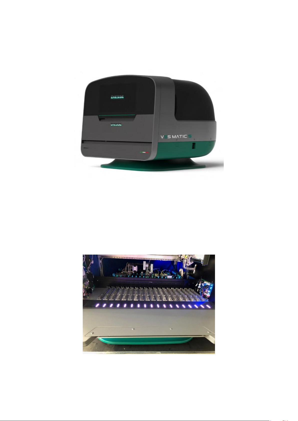
1.4 DESCRIPTION OF THE INSTRUMENT
Ves-Matic 5 is a bench top instrument programmed by a specific software to perform
the ESR test independently and automatically.
Figure 1 –Ves-Matic 5
Figure 1 shows the Ves-Matic 5 model (REF: 10360).
The high level of automation gives the instrument features such as:
- Random access
- Continuous loading
The instrument uses cameras for recognising the tubes and the sample characteristics.
The samples must be inserted in the test tube rack on the front of the machine.
Rev. 2.2 (05.2022)
VES MATIC 5 | USER MANUAL
13
1.4.1 Front side
1.4.1.1 Introduction of samples
By opening the door (2) the racks with samples can be introduced into the loading
compartment (Figure 2).
Figure 2 –Front view
Front View Legend:
1Instrument control unit with Touch Screen display
2Rack insertion compartment door
3Access door to printer and auxiliary USB port
1.4.1.2 Front view - door open
Figure 3 - Front view open
Ves-Matic 5 has 18 available positions (guides) for the insertion of racks with samples, for
a maximum of 180 samples. The rack insertion and extraction are guided by the SW and
1
2
3
3
14
VES MATIC 5 | USER MANUAL
Rev. 2.2 (05.2022)
by the LEDs in front of each guide, whose colour is consistent with that shown on the
instrument screen.
View legend of Figure 3:
1Sample racks loading compartment
2Analysis module
3Tube pick-up clamp
1.4.1.3 Front view - lower door
View legend in Figure 4:
1Rack insertion Compartment Door
2Printer
3Front USB port
4Check device Insertion Compartment
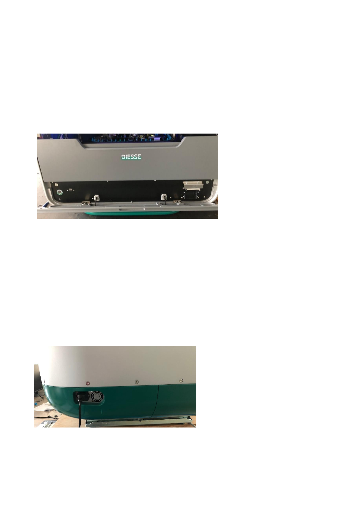
1.4.2 Back side
1.4.2.1 Power supply
The electrical connections of the instrument are positioned on the rear left side, as
shown in Figure 5
View legend in Figure 5:
1Filtered socket with fuse housing
2
Figure 4 - Lower door
1
2
3
4
Figure 5 - Back view
1
2
Rev. 2.2 (05.2022)
VES MATIC 5 | USER MANUAL
15
2Cooling fan
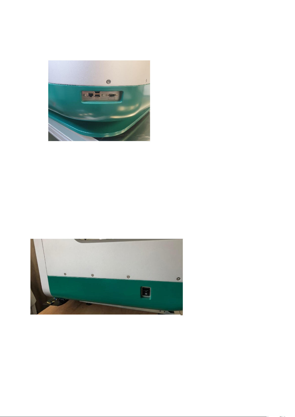
1.4.2.2 Connection panel
View legend in Figure 6:
1Ethernet network socket
2USB Host dual port
3Connection to Host
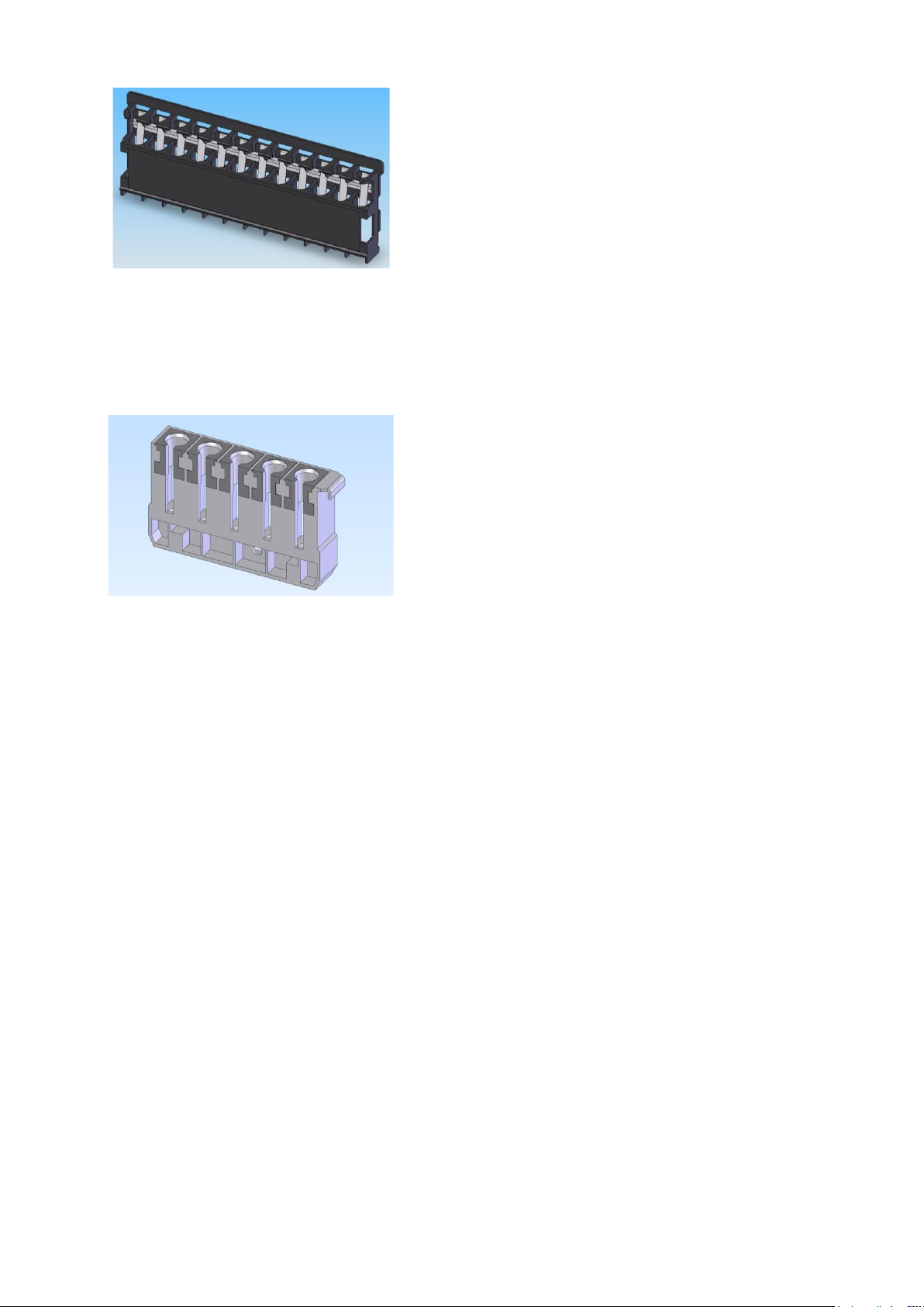
1.4.3 Right side
View legend in Figure 7:
1"I" [ON]/ "O" [OFF]/ Switch
Figure 6 - Connection panel
Figure 7 - Right side
1
1
2
3

16
VES MATIC 5 | USER MANUAL
Rev. 2.2 (05.2022)
1.5 VES-MATIC 5 MODELS
The Ves-Matic 5 instrument is currently produced in a single model that can be adapted
to different types of Racks during installation, for compatibility with the type of cell
counter rack in the laboratory.
The currently supported rack models are as follows:
Sysmex/Mindray/Horiba BLOOD COUNTER RACKS
Advia/Siemens BLOOD COUNTER RACKS
Beckman Coulter BLOOD COUNTER RACKS
BECKMAN COULTER Blood counter Racks (5 positions)
SYSMEX /MINDRAY /HORIBA MODEL RACKS:these racks are white with 10 positions with
adapter (optional for Sysmex racks only, indicated by the arrow).
Figure 8 - Sysmex Rack with adapters / Horiba / Sysmex without adapters
For ADVIA/SIEMENS MODEL RACKS: these racks are grey with 10 positions.
Figure 9 - Advia/Siemens Racks
BECKMAN COULTER MODEL RACKS
:
These racks are black, with 12 positions.
Rev. 2.2 (05.2022)
VES MATIC 5 | USER MANUAL
17
Figure 10 - Beckman Coulter Rack
BECKMAN COULTER MODEL RACKS
:
These racks are grey, with 5 positions.
Figure 11 - Beckman Coulter 5-position Rack
1.6 COMPATIBILITY WITH LAVENDER TOP TUBES
Ves-Matic 5 is configured to use the same test tubes from the blood cell counter present
in the laboratory. However, different types of test tubes can be used at the same time.
The tubes compatible with the instrument are, in detail:
-BD –Vacuitainer
-BD - Vacutainer conventional closure
-Greiner - Vacuette
-FL Medical - Vacumed
-KIMA - Vacutest
-Sarstedt S - 3.4 ml Monovette
-Sarstedt S - 2.7 ml Monovette
-Sarstedt S - 2.6 ml Monovette
-Sarstedt S - 1.8 ml Monovette
-Sarstedt S - 1.2 ml Monovette
-BD MAP
-BD Microtainer
-Greiner - Minicollect
-KIMA - Microtest

18
VES MATIC 5 | USER MANUAL
Rev. 2.2 (05.2022)
1.7 TECHNICAL DATA
FIELD
VALUE
Mains voltage
Europe: 230VAC@50Hz; US/Canada: 110-
120Vac@60Hz
Electrical energy consumption
420VA
Fuse block
2 x 5.0 AT (delayed) (5 x 20 mm) UL
Dimensions (mm)
850 (W) x 750 (H) x 830 (D)
Weight
80 kg
Temperature range in operation
from +15 to + 35°C;
Storage from + 5°C to + 45°C
Humidity range
from 20% to 80% without condensation
Central unit
Quad core ARM Cortex A-53 CPU ARM
Cortex A-53, 16 GB eMMC, 4 GB RAM
Display
19" Full HD (1920x1080) LCD with PCAP
Touch Screen
Peripheral Control
based on Everex distributed control
system with peripheral motor control
boards
Operating system
Linux
Analysis module
89 Positions for Sample Tubes
Sample Loading
up to 18 racks simultaneously
Throughput
190 samples per hour. First result after 28
minutes
Walk away mode
Supported
Continuous loading
Supported
Sample mixing
with multiple 180° rotations of the tubes
Collection of analysed samples
reinserted into the original loading rack
LIS Connection
Multiple LIS connection protocols are
available: ASTM / Proprietary
Remote diagnostics
available via Ethernet connection.
Printer
Alphanumeric with 58mm-wide thermal
paper, 36 characters per line, speed 20
mm/sec.
Imaging System
2 high resolution cameras for sample
identification and analysis; 1 standard
camera for internal inspection.
Image processor
Dedicated Quad Core CPU with
integrated GPU for real-time HD image
processing of samples.
Interfaces
2 x RS232C, 2 Host USB, 1 Client USB,
Ethernet
Protection category
CLASS I
Safety standard
EN 61010-1, EN 61010-2-101
EMC
EN61326-1
Installation category
II
Other manuals for VES MATIC 5
1
This manual suits for next models
1
Table of contents
Other Diesse Analytical Instrument manuals


