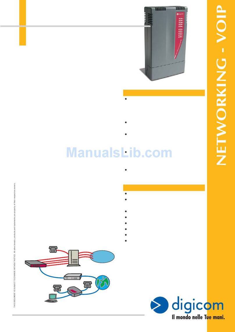
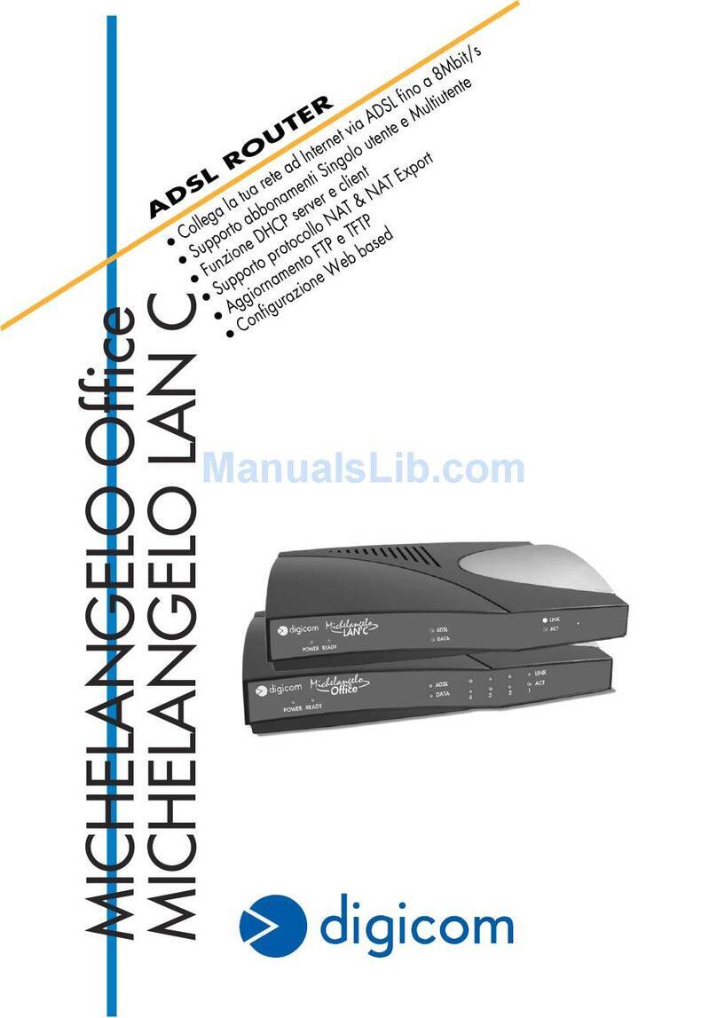
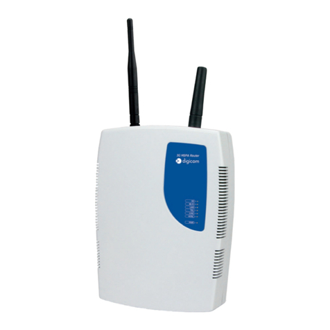
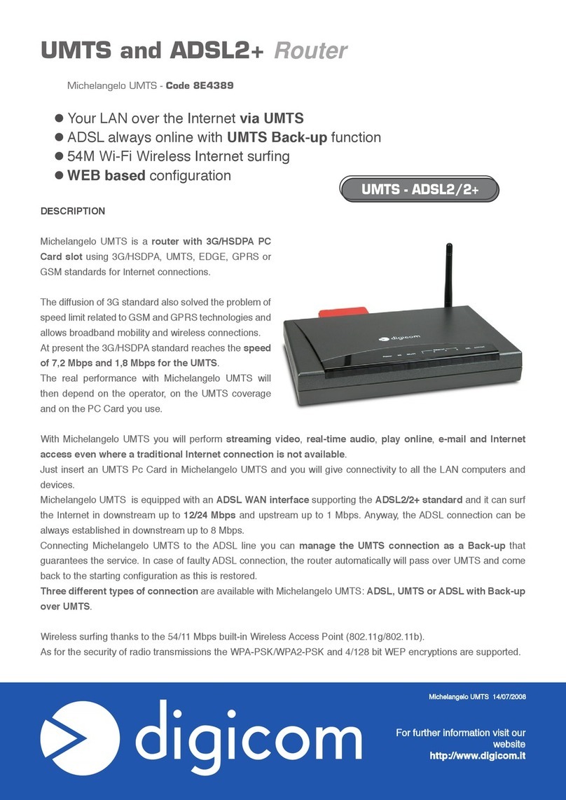
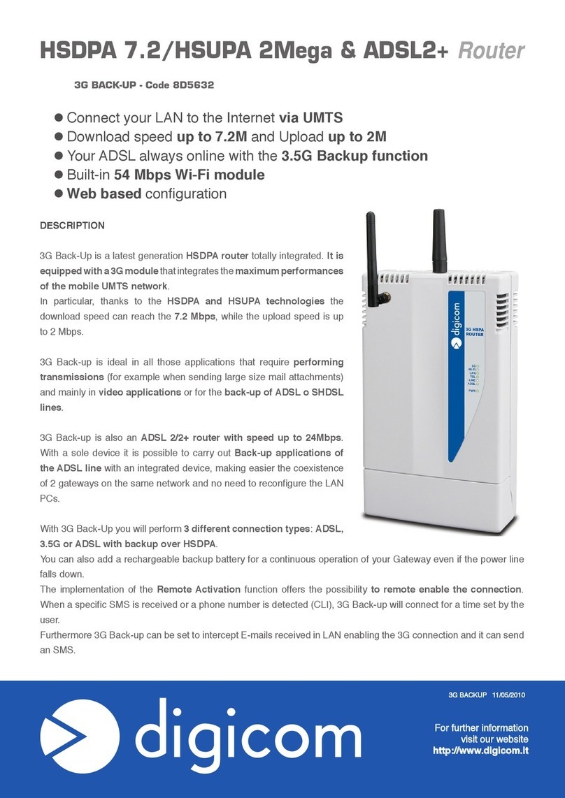
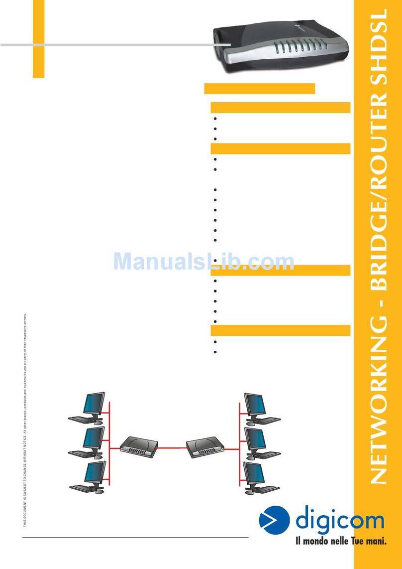
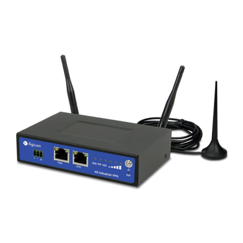
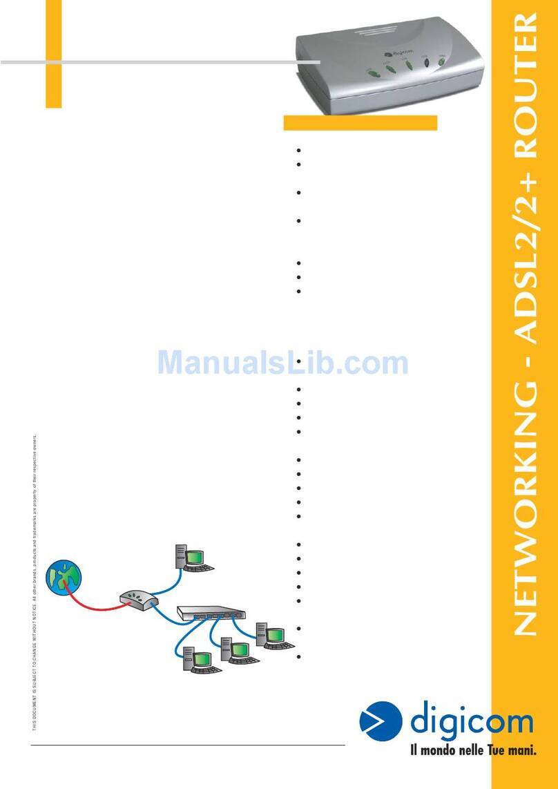
Digicom Michelangelo Gateway User manual

Michelangelo LAN, ADSL Router
1Router Commander Rel 2.0 02/2002
Michelangelo LAN
Router Commander

Product warranty does not apply to damage caused by lightning, power surges or
wrong voltage usage.

3
Contents
Documentation ................................................................................................. 4
Introducing DSL Router Commander ..........................................5
1.1 Logging In ............................................................................................. 5
1.2 Getting Ready Information Required ...................................................... 6
Network Setup Overview ..............................................................8
2.1 Configuring the PCs .............................................................................. 9
Configuring your Router with DSL Router Commander ..............10
3.1 Line Configuration ................................................................................. 1 3
3.1.1 Configuring for RFC 2684 (RFC 1483) Bridged .................. 14
3.1.2 Configuring for RFC 2684 (RFC 1483) Routed ................... 20
3.1.3 Configuring for RFC 2225 (RFC 1577) ............................... 22
3.1.4 Configuring for RFC 2516 ................................................... 23
3.1.5 Configuring for RFC 2364 ................................................... 24
3.1.6 Configuring for Transparent Bridge ...................................... 2 7
3.2 RouteTable .......................................................................................... 28
3 . 3 DHCP ................................................................................................... 3 0
3.3.1 Configuring Your Ethernet card for DHCP ............................ 32
3.4 SNMP ................................................................................................... 33
3.5 DSL Monitoring Application .................................................................. 35
Glossary ........................................................................................ 37
Index .............................................................................................43
1
2
3
4
Software Manual
Documentation
Quick Installation Guide
Please refer to this manual for setting up and connecting your modem/router.
DSL Router Commander Software Manual 1(THIS MANUAL)
This software manual is a softcopy guide that contains information on DSL Router Commander,
a user-friendly user interface that provides a simple way of configuring your router. A
Glossary section is also included to describe the terms used in the manual.
ADSL Ethernet Router Technical Manual 1
The technical manual is a softcopy guide that contains console commands and advanced
router configurationsthat are mostly intended for experienced users.
ATMOS Console Commands Reference Manual 1
The reference manual is a softcopy guide that contains the detailed description of the console
commands. For any advance configurations, you may refer to it for their descriptions.
ISP will be used throughout the manual to denote Internet Service Provider.
1These manuals can be found on the CD-ROM that comes with your package.

5
Chapter…1
Introducing DSL
Router Commander
DSL Router Commander is a user-friendly interface that allows you to initialize, view and
modify your router configurations to match the characteristics of your network environment.
1.1 Logging In
1. Place the ADSL CD-ROM into your CD-ROM Drive. You will be prompted with aMain
Menu, followed by a prompt asking you to install Acrobat Reader for viewing the
manuals. Click OK.
On the Main Menu, select RUN DSL ROUTER COMMANDER.
(If you do not see the Main Menu displayed, you may run the menu.exe file from the ADSL CD-
ROM. You may also run DSL Router Commander by running DslCom.exe file from \Tools\DSL
Router Commander folder on the CD-ROM.)
2. You will be prompted for your log in password. Enter the password as stm (factory's
default) and click OK.
(The factory default for Router IP Address and
Password is 192.168.1.1 andpassword respectively*.
Replace them with your new Router IP Address
and Password if your System Administrator has
changed them. (* "stm" for old models))

6
Software Manual
1.2 Getting Ready Information Required
To configure your router, you need to have the following information ready from your
Internet Service Provider (ISP) and SystemAdministrator.
The following table shows the information required.
a) Check with your ISP:
i) The line protocol to use
ii) For RFC 2684 (RFC 1483) / RFC 2225 (RFC 1577):
The addresses for
WAN IP
WAN Subnet Mask
VPI and VCI values
Default WAN Gateway
DNS Relay
DNS Server (Primary)
DNS Server (Secondary)
For RFC 2516 / RFC 2364:
The PPP Authorization's
User Name
Password
Channel
Authentication
DNS Relay
DNS Server (Primary)
DNS Server (Secondary)
iii) The Framing Mode [not applicable for RFC 2225 (RFC 1577)]
You may also change your login password by selecting the SNMP tab from
the DSL Router Commander.

7
Software Manual
b) Check with your System Administrator:
i) The addresses for
LAN IP address
LAN Subnet Mask
Remote Gateway
ii) To enable or disable NAT

8
Network
Setup Overview
This section gives an overview of a typical network. The addresses indicated are used as
examples throughout the whole manual. You are to replace them with values given by your
System Administrator / ISP.
Chapter…2
PVC=0/35
WAN LAN PC X
PCA
PC B
ADSL Your Router
PCs with
Ethernet cards
WAN IP
202.166.29.154
LAN IP
192.168.1.1 (with NAT)
202.166.30.1 (without NAT)
WAN Gateway = 202.166.29.2
Hub/Switch

9
Software Manual
1. For configuration without NAT:
The range of the IP address used in this example is from 202.166.30.1 to
202.166.30.6 as restricted by subnet mask defined.
Network ID : 202.166.30.0 Broadcast ID : 202.166.30.7
The ISP will have to create a static route:
Network ID : 202.166.30.0 Subnet Mask :ff:ff:ff:f8
Next Hop Gateway : 202.166.29.154
2. For PPPoA and PPPoE:
The WAN IP and WAN Gateway will be dynamically assigned by the PPP
server. There is no need to specify the WAN IP nor to configure a default
route to the WAN Gateway.
2.1 Configuring the PCs
For PCA:
(with NAT) (without NAT)
IP = 192.168.1.11 = 202.166.30.2
Subnet mask = 255.255.255.0 = 255.255.255.248
Gateway = 192. 168.1.1 = 202.166.30.1
For PC B:
(with NAT) (without NAT)
IP = 192.168.1.12 = 202.166.30.3
Subnet mask = 255.255.255.0 = 255.255.255.248
Gateway = 192. 168.1.1 = 202.166.30.1
For PC X:
(with NAT) (without NAT)
IP = 192.168.1.23 = 202.166.30.6
Subnet mask = 255.255.255.0 = 255.255.255.248
Gateway = 192. 168.1.1 = 202.166.30.1

10
Chapter…3
Configuring your Router with
DSL Router Commander
1. For any settings that you are unsure, please check with your ISP or
System Administrator.
2. Based on your selected line configuration, fields that are not applicable
will be grayed out.
3. The values in the screen shots are based on the examples in Chapter 2
- Network Setup Overview. You are required to replace these values
with those given by your ISP or System Administrator !

11
Software Manual
Once you are logged in, you will see the following Main Menu.
Always click Close on the menu to save any changes you have made to your
configurations. If you exit DSL Router Commander without clicking on
Close, changes you have made will be lost!

12
Software Manual
The following describes the menu items:
Line Configuration(see section 3.1 for details)
To select the desired protocol and configure the IP addresses/Subnet Mask that is required
for your network. You may set, modify or view the settings for your configuration.
Route Table(see section 3.2 for details)
To set, view or delete static route(s).
DHCP(see section 3.3 for details)
To add, modify or view the DHCP server for your local network.
(DHCP allows centralized configuration of all workstations’ TCP/IP protocol and IP address
allocation from the server.)
SNMP(see section 3.4 for details)
To manage the list of SNMP community names.
DSL Monitoring Application(see section 3.5 for details)
To monitor the activities of your router from the computer connected to it. Click Close to
exit DSLRouter Commander.

13
Software Manual
3.1 Line Configuration
The different types of configurations available are:
•RFC 2684 (RFC 1483) Bridged or Ethernet Framing
Encapsulation of bridged network data, such as Ethernet frames, in ATM
Adaptation Layer 5 (AAL5) Protocol Data Units (PDU).
•RFC 2684 (RFC 1483) Routed or IP Framing
Encapsulation and Transmission of routed network data, such as IP datagrams,
over ATM Adaptation Layer 5 (AAL5) Protocol Data Units (PDU).
•RFC 2225 (RFC 1577) IPoA
Transmission of IP datagrams andATMAddress Resolution Protocol (ATMARP)
requests and replies over ATM Adaptation Layer 5 (AAL5).
•RFC 2516 PPPoE
Creation and maintenance of a Point-to-Point-Protocol (PPP) session over an
Ethernet link.
•RFC 2364 PPPoA
Creation and maintenance of a Point-to-Point-Protocol (PPP) session over an
ATM link.
•Transparent Bridge
Joining two or more bridged network segments (such as Ethernet) running on
different physical media.

14
Software Manual
i) Select Line Configurationtab. In the Protocol section, click RFC 1483 Bridged.
ii) In the PVC section, enter the VPI and VCI values assigned by your ISP.
iii) In the IP Address section, enter all the required IP addresses assigned to you by your
ISP / SystemAdministrator.
(Depending on your ISP, you may select the option Obtain Wan SettingAutomatically.
The WAN IP Configuration, WAN Subnet Mask and Remote Gateway fields will be
grayed out. The addresses will be allocated by your ISP Server automatically.)
iv) Select the NAT option as determined by your SystemAdministrator. If required, click
Inbound and fill in the data. (See section 3.1.1a - NAT Inbound)
v) Select the Framing Mode option as determined by your ISP.
3.1.1 Configuring for RFC 2684 (RFC 1483) Bridged

15
Software Manual
Applicable to all protocols:
If you overwrite the default LAN IP address / Subnet Mask with new addresses
and click Apply, the following dialog box will be prompted.
Understand the instructions. Click OK to both prompts. Proceed to change your
Ethernet Card's IP / Subnet Mask by carrying out the following steps:
a) From your Windows desktop, right-click on the Network Neighborhood
icon and select Properties.
b) From the Configuration tab, select TCP/IP-> 3Com EtherLink III ISA
[3C509b-TPO] in PnP mode.
(3Com EtherLink III ISA Ethernet Card is used as an example here. Select the TCP/
IP protocol that is binded to your Network Card connecting to your router.)
Click Properties.
(If you do not see a TCP/IP
networking protocol, re-install
your Ethernet card.)
continue on next page...

16
Software Manual
If you have set the subnet mask of the LAN IP to 255:255:255:255, you will
not be able to run DSL Router Commander. This is because only one IP is
allowed on the LAN network and it is already allocated to the router.
c) From the IP Address tab, overwrite
the existing IP Address /Subnet
Mask to the same subnet as the
LAN IP / Subnet Mask you have
entered at the DSL Router
Commander.
Click OK and restart you system if
prompted.
You can now run the DSL Router
Commander with the new IP
address.

17
Software Manual
For Multiple PVCs:
vi) For multiple PVCs, click Multiple PVC.
- In theProtocol section, select RFC 1483 Bridged.
- In the IP Address section, enter the WAN IP Configuration and WAN Subnet
Mask addresses assigned to you by your ISP / System Administrator.
(The WAN IP Configuration must be a unique IP address for different set of PVC
values.)
Depending on your ISP, you may select the option Obtain Wan Setting
Automatically. The addresses will be allocated by your ISP Server automatically.
- In the PVC field, enter the new VPI and VCI values.
- Select the Framing Mode option as determined by your ISP.
- Click Add. A protocol with the new PVC values will be listed.
(To remove a PVC value, click on the respective protocol and click Remove.)
- Click Apply for changes to take effect. Upon configuration successful, you will
see a dialog box, 'Configuration Successful' prompted. ClickOK.
vii) Click Apply for changes to take effect. Upon configuration successful, you will see a
dialog box, 'Configuration Successful' prompted. Click OK.
viii) Click Close to save the configurations and exit.

18
Software Manual
3.1.1a NAT Inbound (optional)
Inbound allows you to list or set up a series of rules to determine what will happen to the
incoming traffic. By default, all incoming packets other than packets arriving in response
to outgoing traffic, will be rejected.
The Interface (e.g. wan as shown in the dialog box below) listed in the table corresponds
to your configured WAN interface.
NAT should always be enabled only on the interface connecting to the
public network or WAN, not the interface connecting to the private network.
i) To add a rule:
Enter the Port, Host IP Address and Protocol required and click Add.
•Port Refers to a 16-bit number (range from 1 to 65535) used by
transport layer protocols (UDP or TCP). Ports are used to
address application or services which run on a Server.
•Host IP Address Refers to the IP address of a local application server (e.g.
HTTP, FTP Server) that will service inbound traffic request
from Internet. The router will forward those requests
according to the list.
•Protocol Refers to the IP protocol, either TCP or UDP.
•Port/Proto Refers to thePort and Protocol used for the interface.
•New IP Addr Refers to the new IP address on the private network which
the packet’s destination IP address should be translated to.
(Illustration is based on RFC 1483 Routed)

19
Software Manual
To remove a single interface
To remove one of the interface, click on it and click Remove.
To remove all interfaces
To remove all interfaces, click Remove All.
ii) Click Exit.

20
Software Manual
i) Select Line Configuration tab. In the Protocol section, click RFC 1483 Routed.
ii) In the PVC section, enter the VPI and VCI values assigned by your ISP.
iii) In the IP Address section, enter all the required IP addresses assigned to you by your
ISP / SystemAdministrator.
iv) Select the NAT option as determined by your SystemAdministrator. If required, click
Inbound and fill in the data. (See section 3.1.1a - NAT Inbound)
v) Select the Framing Mode option as determined by your ISP.
3.1.2 Configuring for RFC 2684 (RFC 1483) Routed
To change the LAN IP address / LAN Subnet Mask at the LAN IP Configuration
/LAN Subnet Mask field, read the Note on page 15.
Other manuals for Michelangelo Gateway
4
Table of contents
Other Digicom Network Router manuals

Digicom
Digicom VOICEGATE H.323 User manual

Digicom
Digicom 3G Industrial Router VPN Pro User manual

Digicom
Digicom Michaelangelo LANPro 8D5517 User manual

Digicom
Digicom 3G Router AM11 User manual

Digicom
Digicom Michaelangelo Office Pro ADSL Router User manual

Digicom
Digicom 8E4589 User manual

Digicom
Digicom 8E4087 User manual

Digicom
Digicom Michelangelo SHDSL 8E4338 User manual

Digicom
Digicom External GSM Modem User manual

Digicom
Digicom ADSL2+ Router User manual