CONTENTS vii
FIGURES
1-1
PDP-11 /23-PLUS Computer System ........................................
1-2 Control Panel
Switches
and Indicators..................................... 2
1-3 Installation
Checklist..
.............................................................. 3
1-4 RL02 Disk Drive (Front View).................................................... 4
1-5 Disk Cartridge Loading............................................................. 6
2-1
Program Code and Name......................................................... 12
2-2 DLDP+ Help
Message.
............................................................ 13
2-3 Example of a Directory Listing.................................................. 13
2-4 Example of a Diagnostic Chain................................................. 14
3-1
PDP-11 /23-PLUS System Unpacking Instructions....................
28
3-2 Installation of Cabinet
Legs
and Stabilizer
FooL.....
................. 29
3-3 PDP-11 /23-PLUS System (Rear Panel Removed)....................
30
3-4 RL02 Lower Disk Drive (Rear View)..........................................
31
3-5
874
Power Controller (Front View) ........................................... 32
3-6 PDP-11
/23B
Subsystem (Rear View) .......................................
33
3-7 PDP-11 /23-PLUS System Cable Connections..........................
34
3-8 RL02 Head Positioner Restraining Bracket............................... 35
3-9 PDP-11 / 23-PLUS Control Panel Operation .............................. 37
3-10 PDP-11 / 23-PLUS Troubleshooting Flowchart ..........................
38
4-1
KDF 11-B Diagnostic LED Display.............................................
50
5-1 PDP-11
/23B
Subsystem...........................................................
63
5-2 Basic PDP-11 /23-PLUS
System's
Module Location in
an H9276 Backplane.................................................................
64
5-3 KDF11-B Jumper, Switch, and Diagnostic
Display Locations.....................................................................
65
5-4 MSV11-P Memory
Factory
Jumper Locations...........................
71
5-5 DZV
11
Factory
Jumper and Switch
Locations
.......................... 72
5-6 RLV12
Factory
Jumper
Locations
............................................ 74
5-7 BA11-S
Major
Assemblies......................................................... 75
5-8 H9276
Connector
and Jumper Locations.................................. 75
5-9 Control Panel Printed Circuit Board .......................................... 76
5-10 PDP-11 /23-PLUS Distribution Panel (H349) ............................. 77
6-1 Standard EIA Interface..............................................................
81
6-2 Telephone Line Interface Via Data Set .....................................
81
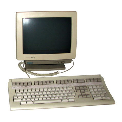
6-3 VT100 Video Terminal.............................................................. 82
6-4 LA120 DECwriter 111...................................................................
84
7
-1
PDP-11 /23-PLUS Power Connectors.......................................
87
8-1 PDP-11 /23-PLUS System (H9276) Two Backplane
Configuration............................................................................ 92
8-2 PDP-11 /23-PLUS System Three Backplane Configuration .......
93
8-3 KDF 11-B Jumper, Switch, and Diagnostic Display
Locations.................................................................................
95
8-4 MSV11-P Jumper Locations..................................................... 104
8-5 CSR Bit Allocation.................................................................... 107
8-6 Left and Right Side Panel Removal...........................................
111
