Digitrax Super Empier Builder User manual

RDigitrax
Command
Control
TM
EMPIRE BUILDER
Super
Advanced
Digitrax Command Control
Starter Set
Manual
Includes:
DB150 Command Station/Booster,
DT400 Series Throttle,
UP5 Universal Panel,
IR Operation with UR90, &
Radio Operation with UR91
DDiiggiittrraaxx,,
IInncc..
450 Cemetery ST #206
Norcross, GA 30071 USA
(770) 441-7992 Fax (770)441-0759
www.digitrax.com
Digitrax Manuals & Instructions are updated periodically.
Please visit www.digitrax.com for the latest version of all manuals.
This manual was updated 11/03.
L
o
c
o
N
e
t
R

1
1.0 Introduction 6
2.0 Super Empire Builder Quick Start Guide 7
2.1 Connect the DB150 to the track & transformer 8
2.2 Plug In The UP5 Universal Panel or UR91 Radio Receiver 8
2.3 Plug In Your DT400 Series Throttle 8
2.4 Turn track power on 9
2.5 Connect Your Layout To The Super Empire Builder 11
2.6 DT400 Display Basics 11
2.7 Select & Run An Analog Loco on Address “00” 12
2.8 Decoder Address Basics 14
2.9 How To Select & Run A DCC Equipped Loco 15
2.10 Shutting Down the System 17
2.11 Resuming your session 17
2.12 Quick Start Problems? 18
3.0 LocoNet: The Digitrax Difference! 19
3.1 System Architecture 19
3.2 Event Driven or Polled? 19
3.3 Network Speed 20
3.4 LocoNet Personal Edition 20
3.5 LocoNet Expansion 20
4.0 Installing Digitrax On Your Layout 22
4.1 Direct Home Wiring vs. Common Rail Wiring 22
4.2 Recommended wire sizes for power bus & track feeders 22
4.3 Other Track Wiring Considerations 23
4.4 Layout Power Districts 23
4.5 Adding a DB150 Booster 24
4.6 Setting Up A Programming Track 25
4.7 Reverse Section Wiring 26
4.8 Using a DB150 as an AutoReversing Booster 27
4.9 Using PM42 for Power Management & AutoReversing 28
4.10 Using DC and DCC together on the same layout 28
4.11 LocoNet Wiring Components 29
4.12 LocoNet Throttle Jacks & LocoNet Connection Jacks 30
4.13 UP5 Panel Hook-up 31
4.14 Troubleshooting Layout Wiring 33
5.0 DB150 Control Panel 34
5.1 Power Input 34
5.1.1 Transformer 35
5.1.2 Heat Dissipation 35
5.2 Power On Indicator 35
Digitrax Super Empire Builder Set Manual
Includes DT400 Series Throttles, DB150 Command Station, UP5,
IR Operations with UR90 & Radio Operation with UR91
Table of Contents

5.3 Ground Terminal 35
5.4 RAIL A & RAIL B Terminals 36
5.5 TRACK STATUS Indicator 36
5.6 OFF LINE Indicator 36
5.6.1 Troubleshooting DB150 Shutdowns 36
5.7 CONFIG A & B 37
5.8 LocoNet Connection Jacks A & B 37
5.9 MODE Switch 37
5.10 SCALE Switch (O/G HO N) 37
5.10.1 Track Voltage Adjustment 37
5.11 DB150 Audible Sounds 38
6.0 DT400 Series Throttle Control Panel 38
6.1 General Information 38
6.2 L(Left) & R(Right) Throttle Knobs 40
6.3 Liquid Crystal Display (LCD) 41
6.3.1 Loco Icon 41
6.3.2 Direction Indicators 41
6.3.3 Smoke Icon 41
6.3.4 Mode Indicator 42
6.3.5 L(Left) & R(Right) Throttle Display 43
6.3.6 Text Area 43
6.3.7 L & R Bar Graph 43
6.3.8 Function Display 44
6.3.9 Track Power Indicator 44
6.3.10 Tetherless Indicator 45
6.3.11 L & R Semaphores-Cab Signaling 45
6.4 FUNC Key 45
6.5 MU Key 46
6.6 LOCO Key 46
6.7 SWCH Key 46
6.8 L & R Reverse Keys 46
6.9 Y + & N - Keys 46
6.10 DISP Key 47
6.11 PROG Key 47
6.12 EDIT Key 47
6.13 FIND Key 47
6.14 BACK Key 47
6.15 PWR Key 47
6.16 OPTN t Key 48
6.17 CLOC c Key 48
6.18 EXIT Key 48
6.19 ENTER Key 48
6.20 EMRG STOP Key 48
6.21 Full Numeric Keypad 49
6.22 Infrared Emitters 50
2

7.0 Track Power On/Off 50
7.1 Track Power On 50
7.2 Track Power Off 51
8.0 How To Select and Run Trains 51
8.1 The SEL Message 51
8.2 DCC Address Ranges & Display 52
8.3 Selecting An Address On A Throttle 52
8.4 Recall a Loco 54
8.5 Stealing: Forcing An Address Selection 55
8.5.1 Slot Following 56
8.6 “slot=max” Message 56
9.0 Locomotive Speed Control 57
10.0 Stop 57
10.1 Setting A Loco to Zero Speed 57
10.2 Emergency Stop 57
11.0 Locomotive Direction Control 58
12.0 Controlling Functions 59
12.1 Controlling F0-F8 59
12.1.1 Function 0 (F0) 60
12.1.2 Function 1, 3, 4, 5, 6, 7, 8, 9, 10, 11, & 12 Keys 60
12.1.3 Function 2 (F2) 60
12.2 Controlling Functions On Consisted Locomotives 61
13.0 Multiple Unit Operations 61
13.2 Removing A Loco From A Consist 64
13.3 Nested Consisting 64
13.4 MU of Mismatched Locomotives 64
14.0 Releasing An Address From A Throttle 64
14.1 Dispatching addresses or consists 65
15.0 Programming and Configuration 66
15.1 Using the DT400’s key pad in Programming Mode 67
15.2 Programming Mobile Decoder Addresses 68
15.3 How to Program Other Configuration Variables 71
15.3.1 Hex Display & Decimal Display 71
15.3.2 Programming CVs Other Than Addresses 71
15.4 Operations Mode Programming 73
15.5 Busy or Fail Message 75
16.0 How Your DB150 Manages 22 Addresses 76
16.1 22 “Slots” For Addresses 76
16.2 Address Purging Strategy 77
17.0 Decoder Status 77
17.1 To Change the Status of a Decoder 78
17.2 Note for Non-Digitrax Decoder Users 79
18.0 Sw (Switch) Mode 79
19.0 Edit Fast Clock 81
19.1 Fast Clock Basics 81
3

19.2 Stop the Fast Clock 82
19.3 Edit Fast Clock Time, Rate & Alarm 82
20.0 FIND Key & Digitrax Transponding 83
21.0 Shut Down and Resume Procedures 84
22.0 IR & Radio Receivers UR90 & UR91 85
22.1 Powering UR90 & UR91 Receivers 85
22.1.2 UR90/UR91Track Status Indicator Hook Up 86
22.2 Installation Basics UR90 & UR91 88
22.3 UR90 Infrared Receiver Installation 89
22.4 UR91 Radio Receiver Installation 90
22.4.1 Resolving Radio Reception Problems 92
23.0 Tetherless Operation of DT400/R 92
23.1 LocoNet ID Change 94
23.2 Tetherless Operation 95
23.2.1 Control Lock 97
24.0 DT400 Battery 97
24.1 Battery Installation 97
24.2 Low Power Indicator 98
24.3 Battery Replacement 99
25.0 Customizing Your DT400 99
25.1 DT400 Option #1 101
25.1.1 Ballistic or Straight Line Tracking 101
25.1.2 Key & Knob Clicks On/Off 101
25.1.3 Local/Global Stop 101
25.2 DT400 Option #2 102
25.2.1 Throttle Default Decoder Operation 102
25.2.2 Tetherless Operation Mode 102
25.3 DT400 Option #3 104
25.3.1 LCD Backlight Brightness Setting 104
25.3.2 Fast Clock Format 104
25.3.3 Recall Stack Depth 104
25.3.4 Tetherless Release 104
25.4 DT400 Option #4 106
25.5 DT400 Option #F 106
25.6 DT400 Option #6 106
26.0 DB150 Option Switch Setup 107
27.0 Troubleshooting 110
27.1 Nothing is responding 110
27.2 Emergency Stop 110
27.3 Can’t select a loco address on my throttle 110
27.4 Clean Track 111
27.5 The Quarter Trick 111
27.6 The LT1 Tester 111
27.7 Decoder Won’t Respond 111
27.8 Mechanical Drive Train Problems 112
4

27.9 “Strange” Locomotive Lights 112
27.10 Lights Work But No Motor Response 112
27.11 Lights Flash First Time Loco Placed On Track 113
28.0 Glossary 113
29.0 FCC Information 122
30.0 Warranty and Repair Information 123
5
Digitrax, Inc. is not responsible for unintentional errors
or omissions in this document.
Digitrax, the Digitrax Train Logos, LocoNet, Empire Builder, Super Empire
Builder, Chief, Super Chief, Zephyr, Jump and others are trademarks of Digitrax,
Inc.
This manual may not be reproduced in any form or translated into other languages without the
express written permission of Digitrax, Inc.
©Digitrax, Inc. All Rights Reserved. Printed in USA REV 11/03
Components included in the Super Empire Builder set are covered by US
Patents 6,275,739, 6,533,223, 6,367,742 B1, 6,533,224, and others.

1.0 Introduction
Congratulations on your purchase of a Digitrax Super Empire Builder Digital
Command Control Set!
Digitrax provides a complete solution to layout control. The Digitrax
Command Control system lets you operate your layout the way you want to.
With LocoNet you simply connect system components to build the layout con-
trol system that you’ve always wanted! The Digitrax system reduces and sim-
plifies layout wiring for new layouts. If you already have a layout, you proba-
bly won’t need to rewire to install the system and get all the benefits of
Digitrax Command Control.
Your Super Empire Builder Starter Set contains:
The DB150 is the system’s DCC command station. It generates the
DCC signals that control decoders and other devices on your layout.
The DB150 is also a DCC booster. Boosters receive DCC signals from
the command station, amplify them and put them on the track along
with the power from the transformer to run the locomotives. You can
have several boosters on your layout to provide additional power to
run more locos.
The DT400 or DT400R is the DCC throttle that comes with the Super
Empire Builder. DCC throttles are the handhelds you use to tell the
command station what you want the decoders to do. You will proba-
bly have several throttles on your layout if you have more than one
person running trains at a time.
A UP5 Universal Panel or UR91 Radio Receiver for memory walka-
round operation or tetherless infrared or radio operation.
LT1 LocoNet & Decoder Tester.
In addition to your Super Empire Builder you’ll need:
A power supply (you many be able to use one you already own) and
One or more mobile decoders for your locomotives. This gives you the
flexibility to choose the “right” decoder for your locos.
Your starter set is just the beginning of an exciting trip. Digitrax will help you
make your model railroading more enjoyable and more realistic. Your success
with and enjoyment of our products are very important to us. After all, this is a
hobby and it is FUN!!!
Please read this manual carefully before you install your system it includes lots
of hints and operating ideas based on our experience with the Digitrax system.
If you have questions not covered by this manual please contact your dealer.
6

2.0 Super Empire Builder Quick Start Guide
These instructions will get you up and running quickly. A full description of all
controls and technical reference information are included later in this manual.
This section assumes that you are using a new set straight out of the box. If
your set is radio equipped, we recommend that you follow this quick start
guide without using radio to learn the basics. When you are successfully run-
ning your radio throttle tethered to the system, then go to Sections 22 & 23 to
learn how to install the radio option.
Figure 1: Super Empire Builder Quick Installation Hook Up
LocoNet Network
(6 Conductor
Flat Phone Cable)
To
Transformer
R
DB150
TRACK
STATUS
POWER
ON
OFF LINE
O/G
N
HO
MODE
O
RUN
LOCONET
A B
SCALE
SLEEPP
R
R
Power District (Double Gapped)
Notes:
1. This example shows a DB150
Command Station.
Any Digitrax Command
Station can be used.
2. The DT400 throttle can be
plugged in any LocoNet Throttle
Jack or LocoNet Connection Jack
on the system.
3. DT400 can also be operated
tetherless with UR90 Infrared
Receiver or UR91 Radio Receiver.
CONFIG B
RAIL B
POWER IN
CONFIG A
RAIL A
POWER IN
GROUND
LOCONET
UNIVERSAL PANEL UP5
R
R
TRACK
STATUS
LocoNet Cable from
Port A or B
plugs into either
LocoNet
Connection
Jack in
rear of UP5
or UR91 with
Radio Equipped
Super Chief
R
R
FUNC MU
MU
SWCH
R
c
LOCO
Y +
L
t
CBABACK
OPTN CLOCPWR
10 11 12
1 2 3
4 5 6
ENTER0EXIT
7 8 9
DISP
PROG
EDIT
FIND
_
R
L
DT400
N
EMRG
STOP
7

2.1 Connect the DB150 to the track & transformer
1. Set the DB150’s SCALE Switch to the scale you are running (N,
HO, O\G). Use the lowest setting (N, HO, or O/G) that will run your
layout.
2. Set the DB150’s MODE Switch to the RUN position.
3. Connect the two terminals on the DB150 marked POWER IN to the
transformer.
4. Plug in the transformer to power up your booster.
5. The DB150 will beep once and the DB150’s “POWER ON” indicator
will come on.
2.2 Plug In The UP5 Universal Panel or UR91 Radio Receiver
1. Using the short LocoNet cable provided, connect either of LocoNet
jacks on the back of the UP5/UR91 to either the A or B LocoNet
Jack on the DB150. If you are using a UR91, plug in the power sup-
ply that was included with your radio equipped set. After completing
Quick Start, see Section 4.13 for information about Universal Panel
Track Status Lights.
2. If you choose not to hook up the UP5/UR91 during the initial installa-
tion, simply plug the DT400 throttle directly into either LocoNet
Jack A or B on the DB150.
3. Remember if your set is radio equipped, please follow these quick
start instructions using your DT400R as a tethered throttle without
radio control. See Sections 22 & 23 for setting up the radio option.
2.3 Plug In Your DT400 Series Throttle
1. Plug the DT400 series throttle into either LocoNet jack on the
UP5/UR91 or DB150.
2. First, you will see the DT400 version number screen:
MODE
O
RUN
SLEEPP
O/G
N
HO
SCALE
8
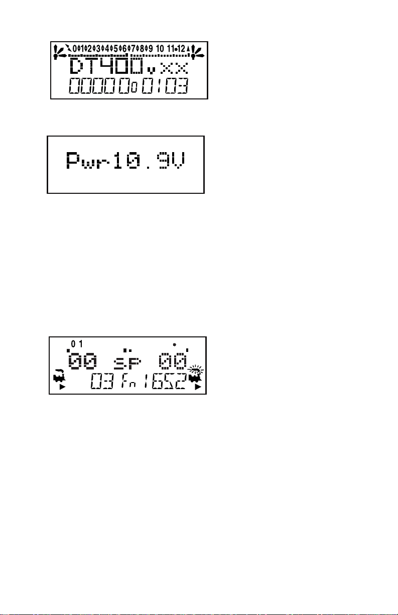
This screen shows the DT400’s
software version number. It is
displayed for a few seconds
each time you power on the
DT400.
3. Next you will see the power indicator screen:
This screen indicates the power
available to the throttle. When
you are plugged in to LocoNet,
this value will be between 9 &
15 volts. when you insert a bat-
tery or unplug from LocoNet,
the value displayed will be the battery power available. When this
number is less than 6.2 volts it’s time to consider replacing or
recharging your battery. See Section 24 for more information about
using batteries with your DT400.
4. The throttle will beep and you will see a screen similar to the follow-
ing. If your throttle is a DT400R, or if there is a UR90 or UR91 con-
nected to your system, you will see additional displays described
later in the radio section. This screen displays current
addresses selected on the L & R
throttles along with their current
speed and direction. The func-
tions that are turned ON for the
active throttle (the one with the
blinking smoke icon) are dis-
played across the top of the dis-
play.
5. When you unplug the DT400 from LocoNet, the LCD will go off
while it is unplugged. It will come on again when you plug in to
LocoNet again.
2.4 Turn track power on
The DT400’s Track Power Indicator and the DB150’s track status indica-
tor show whether track power is on or off. The first time you plug in
your DT400 throttle, track power will usually be off. To run trains,
you will need to turn on the track power. Look at your DB150
and/or DT400 to determine whether the track power is on or off.
9

1. When track power is off:
DB150 TRACK STATUS indicator is off,
DB150 OFF LINE indicator is on, and
DT400 Track Power Indicator is off (Track Power Indicator is a
small dot in the top line on the right side of the LCD).
2. When track power is on
DB150 TRACK STATUS indicator is lit,
DB150 OFF LINE indicator is off, and
DT400’s Track Power Indicator is on
(small dot in the top line on the right side of the LCD).
How To Turn Track Power On and Off
1. Turn track power on:
Press the PWR Key , the DT400 will display a screen similar to this:
Press the Y + Key and the Track Power Indicator on your DT400
display and on your command station will come on.
2. Turn track power off:
Press the PWR Key , then press the N - Key . The Track Power
Indicator on your DT400 and on your command station will go off.
3. Exit PWR mode by pressing the PWR Key again or by press-
ing any other key on the throttle to initiate the next throttle task.
PWR
N
PWR
Y +
This display shows a DT400 in PWR mode.
1. Track power is currently on-indicator is illuminated.
2. The L throttle does not have a loco selected-SEL in
lower L side of display.
3. The R throttle is running address 25 in the
forward direction at 50% speed- 25, loco icon,
smoke icon and direction arrow in lower R side
of display.
4. Press theY+ Key to turn track power on.
Track Power Indicator
PWR
10

2.5 Connect Your Layout To The Super Empire Builder
1. Be sure both the TRACK STATUS indicator and POWER ON indica-
tor on your DB150 are lit.
2. Connect the DB150’s RAIL A and RAIL B terminals to your track.
Connect RAIL A to one rail and RAIL B to the other rail.
3. If you don’t hear any beeps when you connect the DB150 to your lay-
out, no short circuits have been detected. To be sure that the DCC
signal is available everywhere on the layout, use a screwdriver blade
or a coin across the rails to cause a short circuit. You will hear the 5
beeps and the DB150 will shut down. Remove the short and the
DB150 will resume normal operation. Try this at several places
around the layout to confirm that the signal is getting through. If the
short you create does not shut down the DB150, review your wiring
in that area of the layout to be sure you have enough track feeders to
supply power and signal to the track. Since the DCC signal travels
with the power on the rails, it is important to have power to the track
in all locations so that the decoders can see the signal and respond to
your commands.
Since the DCC signal travels with the power on the rails, it is
important to have power to the track in all locations so that the
decoders can “see” the DCC signals and respond to your commands.
2.6 DT400 Display Basics
1. The DT400 handheld has two throttles called the Left throttle (L) and
the Right throttle (R).
2. There are two direction indicators on the DT400. One for the L
LThrottle
Speed
Address
Direction
RThrottle
Speed
Address
Direction
LR
Blinking Smoke Icon indicates
that the R Throttle is active.
Functions displayed
correspond to the active throttle
11

throttle and one for the R Throttle. If the direction indicator is lit,
and there is smoke over the loco icon there is an address select-
ed on that throttle.
3. The direction indicator with blinking smoke indicates which
throttle is currently active. The active throttle is the one for which
function and text information is currently displayed on the LCD
screen. Also, keypad entries control functions for the active throttle.
4. The direction indicator shows the direction of travel of a DCC
equipped loco selected on that throttle, for reverse and for
forward. If you are running an analog loco, the direction indicator
will only indicate change in track polarity and will not necessarily
match the direction of travel of an analog loco.
5. The current mode of operation is shown in center of the bottom line of
the display. The normal operating mode is Fn or function mode for
running trains. In this mode, the throttle knobs and direction keys
control the speed and direction of the locos. The Y + & N- Keys can
also be used to increase or decrease speed. The numeric keypad keys
0-8 are used for direct access to functions. F9-F12 are not available
with Super Empire Builder’s DB150 comand station.
For example, in Fn mode, to increase speed you can either turn the throt-
tle knob clockwise or press the Y + Key. To change the loco’s direc-
tion you can either double click the throttle knob or you can press
the reverse key associated with the throttle you are using. To access
functions on the active address you are controlling, simply press the
numeric key that corresponds to the function you want to activate or
deactivate. When you are in switch mode, the keypad is used for
entering switch commands while the throttle knobs and direction
keys continue to run the trains.
The following examples will help you learn about your new DT400. The
first example shows how to select and run an analog loco, the second
shows how to select and run a DCC equipped locomotive. Once both locos
are selected on your throttle, you can run them both at the same time.
2.7 Select & Run An Analog Loco on Address “00”
1. Place an analog locomotive (one without a decoder) on your layout.
While the analog loco is sitting still, you will hear the characteristic
12
“singing” caused by the DCC track signal when it is applied to ana-
log locomotives. Once the analog loco is moving, this sound will
change and be less noticeable. (Digitrax recommends that analog
locos not be left sitting on DCC powered track for long periods of
time when they are not running.)
2. Check the Track Power Indicator on your DT400’s LCD to be sure
that track power is turned on.
3. Activate the DT400’s right throttle knob “R” by turning it a 1/4 turn in
either direction or by pressing down on the R Throttle knob once.
The R Address will start flashing. If nothing is selected on this throt-
tle it will flash “SEL”.
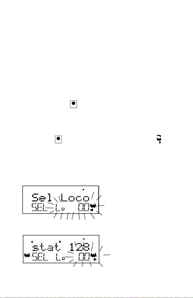
4. Press the LOCO Key . The LCD will show the last address used
and the current decoder status of that address. The DT400 gives you
two options for choosing the address you want to run: throttle knobs
or direct keypad entry. Either use the R Throttle knob to dial up
“00” in the R Address display or press 00 on your keypad. Press the
LOCO Key again to select address 00 on the throttle. The
icon and the address will be blinking until you complete your selec-
tion by pressing the LOCO Key the second time or exit the loco
selection mode by pressing another key to begin another throttle
task. The EXIT Key can be used at any time to return to Fn mode
for normal loco operation. This illustration shows
what will be on your LCD
when you press the LOCO
Key to select an address on
the R Throttle if address
“00” was the last address
selected on the R Throttle
and where no address has
been previously selected for
the L Throttle.
As you browse through the
decoder addresses, the dis-
play will show the current
status of the address.
LOCO
LOCO
13

This illustration shows the
LCD after pressing the
LOCO Key to complete the
selection process. Loco
address 00 is selected on
the R Throttle and is not
moving.
5. Turn the R Throttle Knob clockwise slowly to increase the speed of
the analog locomotive. As the speed increases, the locomotive on the
track will begin to move. Your command station’s TRACK STATUS
indicator should change color as you change the speed setting.
6. Press the R Reverse Key on the right side of the DT400 or dou-
ble click* the R Throttle knob to reverse the direction of the analog
loco. The R direction indicator will toggle between and
The indicator will change each time you press the direction key but,
in the case of the analog loco the indicator only indicates a change
in track polarity-NOT THE ANALOG LOCO’S DIRECTION.
*To double click the throttle knob, quickly press down on the throttle
knob twice within about 1/2 second. You will hear a click each time
you press down on the throttle knob.
7. Turn the R Throttle knob counterclockwise to 0% speed to stop the
analog loco.
2.8 Decoder Address Basics
Each DCC decoder has an address that is used by the system to send com-
mands to that decoder. To select a DCC locomotive and run it on either throttle
or to program any of its CVs using ops mode programming, you must know its
address.
Digitrax decoders are set up at the factory with the “default” 03. This means
that when you take a Digitrax decoder out of the package and install it in your
loco, you can select address 03 on your throttle and run the decoder. The first
CV programmed by most DCC users is the decoder’s address since it is not
very useful to have all of your locos run on address “03.”
If you do not know the address of the DCC locomotive you want to run, you
can simply program the decoder’s address and select it to run using the newly
programmed address. The DB150 included with your Super Empire Builder
R
14

can not read back addresses, so this is the method you will use when you can’t
remember a decoder’s address. With some command stations, like the DCS100,
you can read back the decoder’s address. See your Digitrax Decoder Users
Manual for a complete discussion of decoder addressing.
2.9 How To Select & Run A DCC Equipped Loco
1. Activate the DT400’s left throttle knob “L” by turning it a 1/4 turn in
either direction or by clicking the throttle knob once. The left side
address will begin flashing. If nothing is selected on this throttle it
will flash “SEL”.
2. Press the LOCO Key
. The left side
of the display will
begin flashing.
The illustration above shows the LCD display just after you press the
LOCO Key to select an address on the L Throttle when nothing has
been selected on that throttle before and where address “00” is
selected to run on the R Throttle.
3. Use the numeric keypad to enter 03 or use the R Throttle knob to
select Address “03” in the left side of the display. (The R Throttle
knob changes 1s and 10s, The L Throttle knob changes 100s and
1000s.)
The illustration above shows the LCD display as you browse through
decoder addresses. The display shows the decoder address and its
decoder status. See Section 17 for more information about decoder
status.
4. Press the LOCO Key to select address 03 on the L throttle.
5. The left loco icon will appear in the display with a direction arrow and
“blinking smoke” . The “blinking smoke” indicates which side
of the throttle displays function information on the LCD’s top line.
LOCO
LOCO
15

The illustration above shows the LCD after address “00” is selected on
the R Throttle and address “03” is selected on the L Throttle, We
see the Power On Indicator in the top line, the speed bar graphs at 0
speed and the text area also at 0 speed for both throttles.
6. Use the L Throttle knob to run the DCC equipped locomotive on
address 03. As the value in the left display increases, the locomotive
with decoder address 03 on the track will begin to move. Press the L
Reverse Key on the left side of the DT400 or double click the
L Throttle Knob to reverse the direction of the locomotive.
7. Turn the L Throttle knob counterclockwise to 0 speed to stop the loco.
8. Use the R Throttle knob and R Reverse Key to control the analog
loco and the L Throttle knob and L Reverse Key to control the
DCC equipped loco. You can control both at the same time.
Notice as you use each throttle knob or direction key that the loco with
the “blinking smoke” will change to that side of the throttle. The
side with the “blinking smoke” indicator is the active throttle. To
control the headlight or other functions, the locomotive must be on
the active throttle.
2 digit address 03
Selected on the
L Throttle
Running at 20% speed
In reverse
Function 0, 1, & 3 on.
An analog loco address 00
Selected on the
R Throttle
Running at 25% speed
The direction arrow below
the Loco Icon does not
indicate actual direction
for Analog locos.
Track Power
Indicator ON
Throttle in normal operations
mode indicated by Fn.
In Function (Fn) Mode
Throttle knobs control Loco's
Speed & Direction
Keypad entries control functions
L
R
L
16

2.10 Shutting Down the System
When you are finished with your session, shut down the Super Empire Builder
by turning off power to the system.
Some users prefer to “dispatch” or release all addresses active in their system
before shutting down. This can prevent unexpected results when you power up
the layout again. This procedure is covered in detail in Section 14.
1. Turn track power off: Press the PWR Key followed by the N -
Key , the Track Power Indicator on the DT400 and the Track
Status Indicator on your command station will go off.
2. Move the DB150 command station’s “MODE” switch to the “SLEEP”
position .
3. Turn off the power supply to the system.
The power to the command station can be left on all the time if desired. In
“sleep” mode, the command station consumes very little energy. In this state
the command station provides keep alive power to all throttles that are connect-
ed to LocoNet.
2.11 Resuming your session
When you are ready to resume your session:
1. Turn on the power to the system.
2. Be sure the DB150’s MODE switch is in the “RUN” position All
attached throttles will beep within a couple of seconds to indicate
that LocoNet is active again.
3. Check the track status indicator on the DB150. If it is not lit then turn
track power on as follows: Press the PWR Key followed by the
Y + Key , the Track Power Indicator on the DT400 and the
Track Status Indicator on your command station will come on.
Y +
PWR
MODE
O
RUN
SLEEPP
N
PWR
17

2.12 Quick Start Problems?
If you encountered problems at any step in this Quick Start Section:
First, try backing up a step until you get results described. The steps included
in this installation procedure are set up so that if you follow them carefully, any
problems you encounter will be easy to isolate & debug.
If that does not work or if you have other questions or problems, we encourage
you to call, fax or e-mail your favorite Digitrax dealer. If your dealer is not
able to help, please contact Digitrax directly.
There are thousands of successful Digitrax installations around the world and
we want to be sure that yours is one of them.
QUICK INSTALLATION Notes for users of Digitrax decoders that have
already been programmed and decoders not made by Digitrax:
1. The DB150 command station defaults to 128 speed step operation so,
if you are using a locomotive with a decoder that does not have 128
step capability you will have to adjust either the decoder or the
DB150 command station so that both are using the same number of
speed steps to communicate. You can status edit each individual
decoder (see Section 17) or you can change the DB150’s system
default and run all of your decoders with fewer speed steps to
accommodate these decoders (see Section 26).
2. If you can’t control the operation of the lights in your decoder
equipped locomotive with the DT400 (in default 128, or 28 speed
step mode), be sure that the decoder itself is programmed in
advanced 28 speed step mode. Please refer to Section 17 for correc-
tive measures.
What’s Next?
Now that you have successfully set up your Super Empire Builder Set, it’s time
to learn more about the features and options offered by Digitrax and the
LocoNet system. Read the manual and take time to understand and master each
topic. Your Super Empire Builder Set is the gateway to all the possibilities and
options offered by Digitrax so the best advice is to take it step by step and
don’t try to do everything at once. The Digitrax Big Book of DCC is another
excellent resource available to you as you expand your layout. The Big Book is
full of examples that show you how you can have even more fun with your lay-
out.
18

3.0 LocoNet: The Digitrax Difference!
3.1 System Architecture
System architecture is the biggest difference among DCC sys-
tems. System architecture is the way the components of a DCC
system communicate among themselves. Digitrax LocoNet is a
Peer to Peer local area network (LAN) designed specifically for
model railroad operation. LocoNet wiring is cost effective,
flexible and expandable to accommodate almost anything you want to do with
your railroad today and in the future.
The system architecture used for communication within DCC systems is not
standardized, therefore DCC compatibility encompasses decoders, command
stations and boosters but not throttles and other devices. In addition, devices
that require feedback and other types of signals that are outside the domain of
DCC, such as detection systems and transponding, are not standardized.
LocoNet incorporates both DCC and other technologies that expand the capa-
bilities of your system. Your Digitrax system gives you the best of both worlds
with a system that is compatible with today’s DCC “standards” and also goes
beyond those “standards” to deliver enhanced system performance, multi-for-
mat capabilities and advanced features that are far beyond the scope of DCC.
3.2 Event Driven or Polled?
LocoNet is an event driven network. The command station on LocoNet waits
for input from other components before sending commands to the layout. For
example, if there are 10 throttles on LocoNet and throttle #1 sends a command,
the command station sees it and executes immediately. With a distributed net-
work like LocoNet, new features can be added by simply plugging in new
hardware or software. Since LocoNet is a peer to peer network, devices on
LocoNet can act independently of the command station, too. Feedback is incor-
porated in LocoNet’s communication scheme so you don’t need to wire a sepa-
rate feedback bus.
Other DCC systems typically use polled buses or “networks.” In this case, the
command station must “ask” each of the throttles or other devices in turn: “Do
you have input for me?” The device must wait for the command station to poll
all the devices on the bus before it sends the command. This arrangement can
slow down response times and limit the number of devices that can be handled
by the system as more and more devices are added. With centralized processing
in a master/slave control type system like this, adding new features usually
means updating the command station software when new components are
added since devices can’t operate on the system unless the master command
station knows how to handle them. To add feedback capabilities to this type of
system, a separate feedback bus may also be necessary.
L
o
c
o
N
e
t
R
19
Table of contents
Other Digitrax Control System manuals


Popular Control System manuals by other brands

PROAIM
PROAIM P-MC-CNL-01 Assembly manual

Reliance Foundry
Reliance Foundry R-7186 Installation

Mitsubishi Electric
Mitsubishi Electric MCC-50A Installation and instruction manual

Gossen MetraWatt
Gossen MetraWatt SMARTCONTROL ECS installation instructions

kenall
kenall Indigo-Clean IC100 installation instructions

iAIRE
iAIRE EC-CHAS5-VBA0 Series manual


