Nabco GT20 8300 User manual

1 of 34
GT20 8300-8350 Overhead Concealed Swing Door Operator
Installaon Manual
P/N C-00183 Rev 8-31-16
Nabco Entrances Inc. S82 W18717 Gemini Drive Muskego, Wisconsin 53150
Phone: (877) 622-2694 Fax: (888) 679-3319 www.nabcoentrances.com
Table of Contents
3
3
4
SECTION 3.1 To the Installer ...............................................................4
SECTION 3.2 Objecve ....................................................................4
5
SECTION 4.1 Technical Data ................................................................5
SECTION 4.2 Required Tools ...............................................................6
SECTION 4.3 Windload ....................................................................7
SECTION 4.4 Power Output ................................................................8
SECTION 4.5 Mechanical Operaon of Door ..................................................8
SECTION 4.6 Types of Installaon ...........................................................8
SECTION 4.7 Handing .....................................................................9
SECTION 4.8 Header Components ..........................................................9
SECTION 5.1 Prep the Jamb Tubes .........................................................10
SECTION 5.2 Install the Header to Jamb Tubes ...............................................10
SECTION 5.3 Install the Frame to Building ...................................................11
SECTION 5.4 Install the Fingerguard ........................................................12
SECTION 5.5 Install the Floor Pivot .........................................................12
SECTION 5.6 Lay down the Saddle Threshold over the Floor Pivot ...............................14
Associated Manuals Part Numbers: GT20 Swing Door Wiring and Programming Manual (P/N C-00169)
GT20 Swing Door Owners Manual (P/N C-00170) for Decal Installation
NABCO Price Book (P/N 16-9244-30) for Sensors, Switches, and Accessories
WARNING

2 of 34
GT20 8300-8350 Overhead Concealed Operator Installaon Manual www.NabcoEntrances.com
P/N C-00183 Rev 8-31-16
SECTION 7.1 Prep the Door Rail ...........................................................18
SECTION 7.2 Install the Base Pivot into the Boom Door Rail ...................................18
SECTION 7.3 Parally Install the Track into the Top Door Rail ...................................19
SECTION 7.4 Temporily Install the Swing Door ...............................................20
SECTION 9.1 Secure the Arm to the Operator ................................................22
SECTION 9.2 Secure the Swing Arm to the Swing Door. . . . . . . . . . . . . . . . . . . . . . . . . . . . . . . . . . . . . . . . .22
SECTION 11.1 Determine the Spindle Rotaon ...............................................24
SECTION 12.1 Connect the Male Connector to the Motor Harness ...............................24
SECTION 12.2 Test the Swing Door .........................................................25
SECTION 13.1 Adjust Preload .............................................................25
SECTION 13.2 FSlam Potenometer (Power OFF) .............................................26
SECTION 13.3 Adjust the Acvaon Angle ...................................................26

3 of 34
www.NabcoEntrances.com GT208300-8350OverheadConcealedOperatorInstallaonManual
Rev 8-31-16 P/N C-00183
Warning labels are universal and used to alert an individual of potential harm to one’s self or to others. The following warning labels are
listed in a hierarchy order that denes the most potential danger rst, and the least potential danger last. Please refer to this page in the
event that a warning label is displayed within this manual and further denition needs to be explained.
high
some
may result in a minor injury
Note: Indicates important informaon that provides further instrucon.
►
►
DANGER
WARNING
CAUTION
DANGER
DANGER
WARNING
WARNING
WARNING
WARNING

4 of 34
GT20 8300-8350 Overhead Concealed Operator Installaon Manual www.NabcoEntrances.com
P/N C-00183 Rev 8-31-16
►
►
►
►
►
►
►
►
►
►
The purpose of this manual is to familiarize the installer and purchaser with the proper installaon and operaon of this system.
It is essenal that this equipment be properly installed and operaonal before the door is used by the public. It is the installer’s
responsibility to inspect the operaon of the entrance system to be sure it complies with any applicable standards. In the United
States, ANSI Standard 156.10 (Full Power) and ANSI Standard 156.19 (Low Energy) covers the GT20 Swing Door Operator Assembly.
Other local standards or codes may apply. Use them in addion to the ANSI standard. Both Full Power and Low Energy Swing door
Units are listed by UL according to UL325 and is idened as such on the label.
Instruct the building owners and operator on the essenals of the operaon of this device. The owner should follow these
instrucons to determine whether the door is operang properly and should immediately call for service if there is any malfuncon.
All installaon changes and adjustments must be made by qualied, NABCO trained technicians. Replacement labels and literature
may be obtained from local NABCO Entrances, Inc. Distributors. If the name of the local distributor is unknown, contact NABCO
Entrances, Inc. at 1-877-622-2694 for assistance.
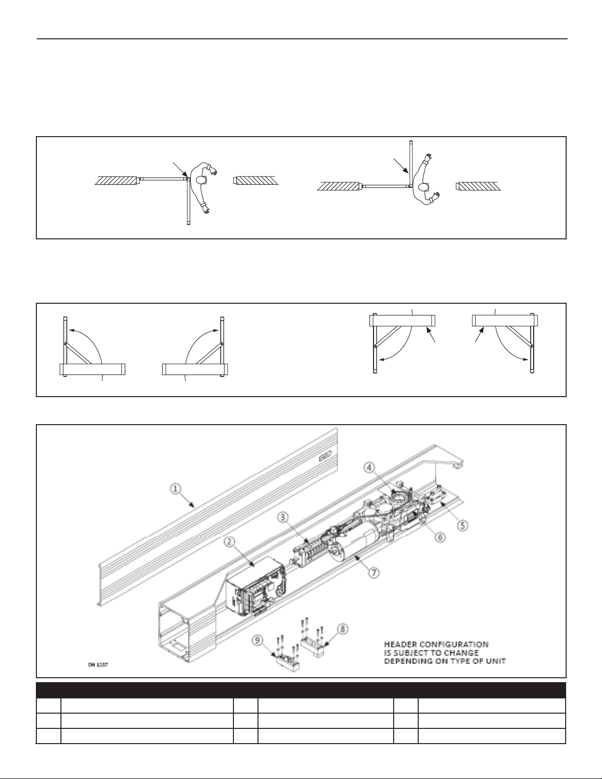
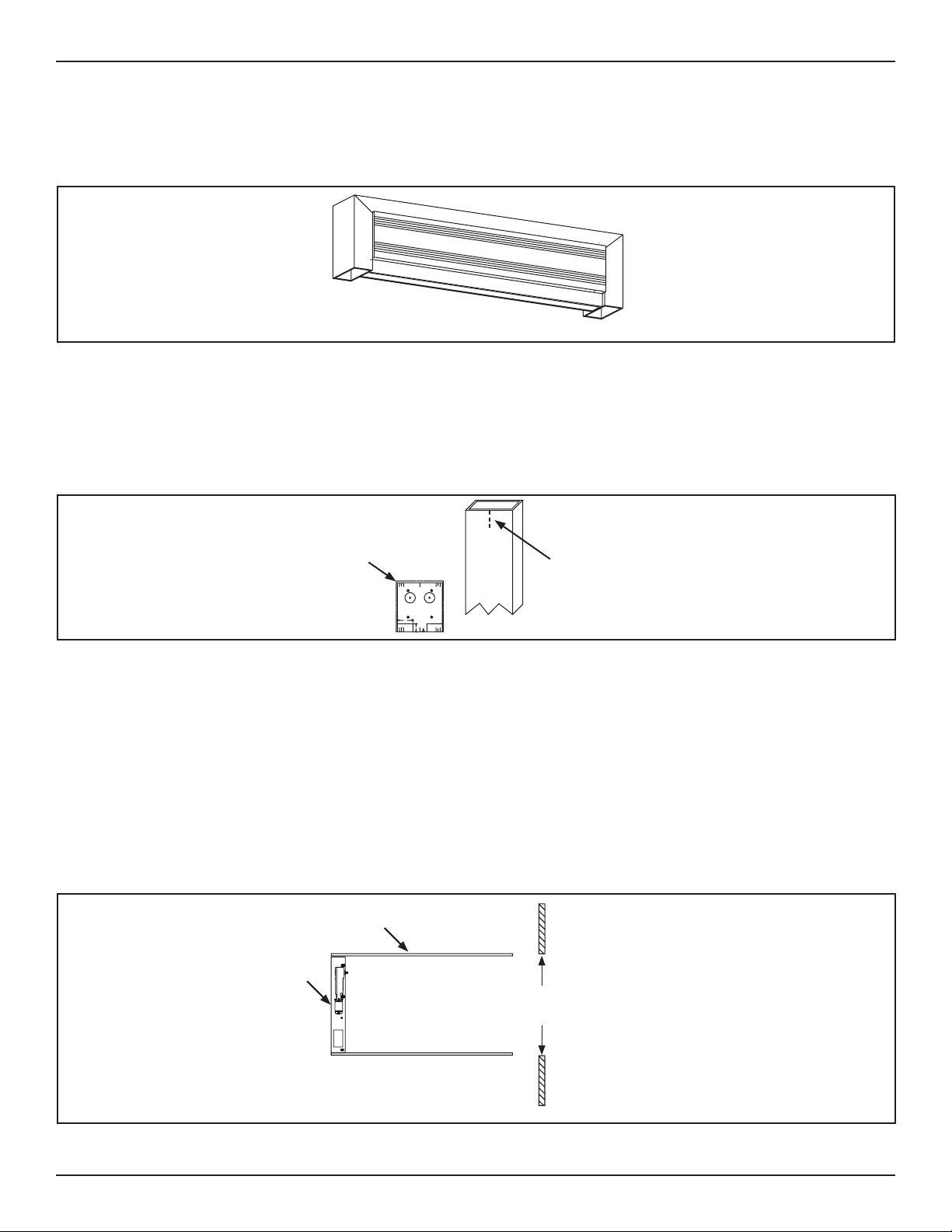
The Swing Door Operator assembly is designed to be installed onto the top surface of the Door Frame, or Door Panel, or between the
Jamb Tubes under the Door Frame (OHC). This manual was created to oer step by step instrucons.
CAUTION

5 of 34
www.NabcoEntrances.com GT208300-8350OverheadConcealedOperatorInstallaonManual
Rev 8-31-16 P/N C-00183
All wiring must conform to standard wiring practices and be in accordance with national
and local electrical codes.
Note: It is recommended for the Installer to use an Electrical Conduit to house all incoming 120 VAC wires.
Table 1
Auxiliary Power Output 24 VDC (±10%) 2A
Table 2
Weight Operator Assembly 23 pounds (10,5 kg)
Motor Type DC Brush Motor (with Encoder installed on Gear Box)
Motor Power Rang 100 W
Power consumpon Max. 560 W
Maximum Door Weight Full Energy 550 pounds (250 kg)
Low Energy 220 pounds (100 kg)
Minimum Height of Door Panel 6 Feet (1.83m)
Width of Door Panel Full Energy 30” - 63” (762mm - 1,600mm)
Low Energy 30” - 48” (762mm - 1,219mm)
Power Transmission Outswing Arm Adjustable Rods aached to Arm Shoe
Inswing Arm Arm slides into Track
Operator Assembly Dimensions Height 6” (152.4mm)
Width Varies
Depth 5-1/2” (139.7mm)
Operang/Shipping Temperature 5 to 122 ˚F (-15...+50 ˚C)
Protecon Type IP 40 (IP 42*) Weather Resistant to Water and Dust
Torque Output Sha Max. 59 pounds (80 Nm)
Distance door hinge - Output Sha Mounng against Door Frame 11”
Door Panel mounng 15”
Door Opening Angle Max. 105˚
Opening Speed Max. 40˚ (opening degree per second)
Closing Speed Max. 40˚ (opening degree per second)
Hold Open Time 0 - 60 seconds
Hold Open Time Night 0 - 180 seconds
WARNINGWARNING

6 of 34
GT20 8300-8350 Overhead Concealed Operator Installaon Manual www.NabcoEntrances.com
P/N C-00183 Rev 8-31-16
Table 3
Number of Signal Inputs ►
►
►
Opcally Isolated Input
Signal Suppression for
Door Mounted Sensor
Signal Suppression determines what angle the door mounted sensor is ignored by the control.
► Programmable - 45 degrees to Full Open
► Programmable - 0 - 60 degrees
Number of Outputs ►
►
Table 4
Simultaneous Pair Synchronizaon
Astragal Funcon
Independent Dual
Low Energy
Full Energy
Air Lock w/oponal plug-in board
Power Boost
Hold Close
Obstacle Detecon ► Door Panel will reverse if an obstacle is detected.
►
Inverse Operaon In the event of a Power Failure or alarm, Inverse Operation opens
the Door Panel under Spring Power for:
►
►
Wind Compensaon Control will gradually increase motor current to counteract wind pressure
Table 5
Sensivity Adjustment for
Obstacle Detecon
Time Delay Adjustment
for Acvaon
Electronic Delay Timer
► ►

7 of 34
www.NabcoEntrances.com GT208300-8350OverheadConcealedOperatorInstallaonManual
Rev 8-31-16 P/N C-00183
DN 1146
50 mph
80 km/h
320 Pa
43 mph
70 km/h
245 Pa
37 mph
60 km/h
180 Pa
30 mph
50 km/h
125 Pa
28 mph
45 km/h
100 Pa
25 mph
40 km/h
80 Pa
9’-8” (3000mm)
9’-5” (2900mm)
9’-2” (2800mm)
8’-8” (2700mm)
8’-5” (2600mm)
8’-2” (2500mm)
8’ (2400mm)
7’-6” (2300mm)
7’-1/4” (2200mm)
7’ (2100mm)
6’-6” (2000mm)
3’-1/4”
(1000mm) 3’-1/2”
(1100mm) 3’-3/4”
(1200mm) 4’-1/4”
(1300mm) 4’-3/4”
(1400mm) 5’
(1500mm) 5’-1/4”
(1600mm)
Clearance Width
Clearance Height
26’-1/4”
(800mm) 35’-7/16”
(900mm)
DN 1147
37 mph
60 km/h
180 Pa
34 mph
55 km/h
150 Pa
31 mph
50 km/h
125 Pa
27 mph
45 km/h
100 Pa
24 mph
40 km/h
80 Pa
21 mph
35 km/h
60 Pa
9’-8” (3000mm)
9’-5” (2900mm)
9’-2” (2800mm)
8’-8” (2700mm)
8’-5” (2600mm)
8’-2” (2500mm)
8’ (2400mm)
7’-6” (2300mm)
26’-1/4”
(800mm) 35’-7/16”
(900mm) 3’-1/4”
(1000mm) 3’-1/2”
(1100mm) 3’-3/4”
(1200mm) 4’-1/4”
(1300mm) 4’-3/4”
(1400mm) 5’
(1500mm) 5’-1/4”
(1600mm)
18 mph
30 km/h
45 Pa
7’-1/4” (2200mm)
7’ (2100mm)
6’-6” (2000mm)
Clearance Width
Clearance Height
DN 1148
Clearance Width
9’-8” (3000mm)
9’-5” (2900mm)
9’-2” (2800mm)
8’-8” (2700mm)
8’-5” (2600mm)
8’-2” (2500mm)
8’ (2400mm)
7’-6” (2300mm)
3’-1/4”
(1000mm) 3’-1/2”
(1100mm) 3’-3/4”
(1200mm) 4’-1/4”
(1300mm) 4’-3/4”
(1400mm) 5’
(1500mm) 5’-1/4”
(1600mm)
Clearance Height
7’-1/4” (2200mm)
7’ (2100mm)
6’-6” (2000mm)
37 mph
60 km/h
180 Pa
27 mph
45 km/h
100 Pa
24 mph
40 km/h
80 Pa
21 mph
35 km/h
60 Pa
18 mph
30 km/h
45 Pa
34 mph
55 km/h
150 Pa
31 mph
50 km/h
125 Pa
26’-1/4”
(800mm) 35’-7/16”
(900mm)

8 of 34
GT20 8300-8350 Overhead Concealed Operator Installaon Manual www.NabcoEntrances.com
P/N C-00183 Rev 8-31-16
X
X
X
X
X
X
X
X
Inverse Swing Door is suitable for:
X
X
X
It is recommended to install a FAIL/SAFE electric lock on Swing doors using Inverse Swing Doors. During normal operaon, the
FAIL/SAFE lock applies connuous pressure to keep the Swing door in a fully closed posion. During a Power Failure, the FAIL/SAFE
lock automacally unlocks, thus allowing the Swing door to fully open.
Do Not install Fail/Secure electric locks on Swing Doors using Inverse Swing Doors. Fail/
Secure electric locks will not allow the Swing door to open during a Power Failure.
The Overhead Concealed (OHC) Operator Assembly is installed inside the Door Frame (directly underneath the top, between (2) Jamb
Tubes). The Operator Assembly can be installed as a:
►
►
►
►Slave
swing door is delayed before opening, and then closes before the Master swing door.
DANGER

9 of 34
www.NabcoEntrances.com GT208300-8350OverheadConcealedOperatorInstallaonManual
Rev 8-31-16 P/N C-00183
Open the Swing door. Bu your back against the Pivot side of Swing door. Swing out the (right or le) arm in the direcon the Swing
door opened.
RIGHT HANDING
DN 1049 LEFT HANDING
Pivot Sle on Swing Door Swing Door
Figure 1
►
►
DN 1480
Threshold
INSWING
LEFT HAND
EXTERIOR SIDE OF DOOR
INSWING
RIGHT HAND
INSWING
RIGHT HAND
INSWING
LEFT HAND
Figure 2
1Header Cover 4Output Sha 7Motor
2 GT20 Control 5Top Pivot Assembly 8Door Stop Assembly
3Spring Unit (for spring-powered closing) 6Gear Box 9Panic Latch Assembly

10 of 34
GT20 8300-8350 Overhead Concealed Operator Installaon Manual www.NabcoEntrances.com
P/N C-00183 Rev 8-31-16
The Overhead Concealed (OHC) Operator Assembly is installed inside the Door Frame (directly underneath the top, between (2) Jamb
Tubes). The GT20 Operator can swing the Door Panel:
DN 1270
Figure 3
1. Measure the full height of exisng Swing door.
2. Obtain and then place the Jamb Drilling Template at the top of Jamb Tube so it is ush.
3. Align the center to the previously drawn center mark.
4. Adhere the Jamb Drilling Template to each Jamb Tube.
a. The Jamb Drilling Template is removable.
Figure 4
DN 0469
Line marking
Center of Jamb Tube
Jamb Drilling Template
5. Drill (4) .391 diameter holes through (4) clearly marked (A)s on the Template. Countersink each screw hole.
6. Obtain (4) Rivnuts provided by NABCO. Install (1) Rivnut into each drilled .391 hole.
7. Drill (1) 1-1/4 inch diameter hole through (1 of 2) clearly marked (B)s on the Template to allow incoming 120 VAC Power.
a. The 120 VAC incoming power must be routed through the Strike Jamb, only.
8. Remove the Template from the Strike Jamb, then adhere same Template to the Pivot Jamb. Repeat steps.
1. Determine which Jamb tube is the Pivot Jamb and the Strike Jamb.
XSwing door pivots on side of Pivot Jamb.
XSwing door locks on side of Strike Jamb.
2. Posion each Jamb tube at both sides of the Header. Be sure to orientate the frame in relaon to the outside of building/room.
Figure 5
DN 0468
Top of Header
Rough
Opening Interior Side of Building
Jamb Tube
ON
3. Secure Header to both Jamb Tubes with (8) 1/4-20 x 3/4 inch Hex Head Cap Screws and (8) 1/4 inch Star Washers from the
Parts bag provided within the Header.

11 of 34
www.NabcoEntrances.com GT208300-8350OverheadConcealedOperatorInstallaonManual
Rev 8-31-16 P/N C-00183
Figure 6
DN 0448
Jamb Tube
Header
Note: It is recommended to pull incoming 120 VAC Power wires through the end of Header for a single Swing door or the
middle of Header for a simultaneous pair Swing door. It is also recommended to install wires into an Electrical conduit.
Note: It is recommended to countersink holes as required to ush the surface.
Note: It is recommended to drill tap threads for anchors in a steel or aluminum structure.
1. Li to posion the assembled Frame into the rough opening. Insert all incoming wiring through the 1-1/4 inch hole located
on side of Header.
2. Plumb Jamb tubes in both planes to ensure the rough opening allows a 1/4 inch clearance. Shim back of Jamb as required.
1/4” Shim and plumb
for proper clearance
DN 0758
Jamb Tube Horizontal
Transom
1/4” Shim and plumb
for proper clearance
Figure 7
Use 1/4 inch diameter anchors with a minimum of 3 per Jamb Tube, maximum is 48 inches on center. Drill 1/4 inch diameter holes in
the face of Jamb and then countersink each hole. Anchors and Fasteners must be appropriate for the type of structure being fastened
into. Anchors and Fasteners are not provided by NABCO.
Figure 8
DN 0402
36” max
48” max
48” max
YYY
Y YY
3. Secure the Frame with Fasteners not provided by NABCO.
Figure 9
DN 0658
1/4” Fasteners
1/4” Anchor Hole(s)

12 of 34
GT20 8300-8350 Overhead Concealed Operator Installaon Manual www.NabcoEntrances.com
P/N C-00183 Rev 8-31-16
Note: Screws must be appropriate for the type of structure being fastened into. Screws are not provided by NABCO.
Note: Do not overghten screws to prevent deforming Weatherstrip Extrusion. Ensure each screw is ush to the Jamb tube.
1. Go to the top of the Pivot Jamb tube, at the center, drop a Plumb Line to the oor.
2. Mark the Center line on the inside face of the Pivot Jamb Tube. It is recommended to use a level.
3. Insert the Weather Strip into both channels located on the Finger Guard Mounng Plate.
a. Spraying silicone (not included) inside the Channels may ease the inseron of the Weather Strip.
Figure 10
DN 0470
Weather Strip
Channels
Weather Strip
Channels
Finger Guard Mounng Plate
SIDE VIEW Assembled Finger Guar
d
4. Line up the Center Notch located down the full length of the Finger Guard Mounng Plate, with the Center Mark located on
the Pivot Jamb Tube. It is recommended to use a level.
Figure 11
DN 0471
Hinge Jamb Tube
Weatherstrip Extrusion
Center Line
Plumb Line
1/8” Screw Hole
1/8 x 1” Self Tapping
Steel or Zinc Plated Screw
5. Drill (3-4) 1/4 inch evenly spaced screw holes down the Finger Guard Assembly.
a. Each screw hole must go through the Weather Strip, Mounng Plate and the Pivot Jamb Tube.
6. Secure the Finger Guard Mounng Plate onto the Pivot Jamb with 1/4 x 1 inch self tapping Screws (zinc or steel plated).
DN 0482 Floor Pivot Assembly
Top Pivot Assembly
Note:
Cover not used on Bi-Fold Units
Figure 12

13 of 34
www.NabcoEntrances.com GT208300-8350OverheadConcealedOperatorInstallaonManual
Rev 8-31-16 P/N C-00183
1. Obtain the Floor Pivot Assembly. The Pivot Sha is not centered on the Floor Pivot. One end is used:
XWith the Finger Guard; so the Pivot Sha measures 3.75 inches away from the Pivot Jamb.
XWithout the Finger Guard; so the Pivot Sha measures 2.75 inches away from the Pivot Jamb.
DN 0484
3.75 inches 2.75 inches
2.75 inches 3.75 inches
Pivot Jamb
Floor Pivot
WITH FINGERGUARDWITHOUT FINGERGUARD
Figure 13
2. Measure and mark the center of the Pivot Jamb and the Floor Pivot.
3. Bu the center mark of the Floor Pivot up against the center mark of the Pivot Jamb.
4. Align both Pivot Shas. Drop a Plumb Line (down the center) from the Top Pivot Sha to the Floor Pivot Sha.
5. Use the Floor Pivot as a template to mark and drill (2) holes for #14 x 1 inch Blue anchors provided by NABCO.
6. Insert (2) #14 x 1” Blue anchors into each hole. Secure the Floor Pivot with (2) #14 x 1-1/2 inch Sloed Flat Head Screws.
DN 0486
Pivot Sha
#14 x 1-1/2”
Sloed Flat Screw
#14 x 1” Anchor
Pivot Jamb
(Center Mark)
Floor Pivot
(Center Mark)
Figure 14
7. Secure the Pivot Cover with (1) 1/2-20 x 7/16 inch Flat Head Machine Screw.
DN 0489
1/4”-20 x 7/16”
Flat Head Screw
Pivot Cover
Note:
Cover Plate not used
on Bi-Fold Doors
Figure 15

14 of 34
GT20 8300-8350 Overhead Concealed Operator Installaon Manual www.NabcoEntrances.com
P/N C-00183 Rev 8-31-16
1. Obtain the Saddle Threshold. The Pivot Side of the Saddle Threshold has a cut out for the Pivot Plate.
Figure 16
DN 0751
Header
4-7/8”
4-1/2”
Jamb Tube
Saddle Threshold
5”
2. Obtain the Saddle Threshold. The Pivot Side of the Saddle Threshold has a cut out for the Pivot Plate. Place the Pivot Side of
the Saddle Threshold over the Floor Pivot Assembly.Ensure the Saddle Track is centered to the Strike Jamb and square.
Figure 17
DN 0754
Saddle Track
Cut Out
(Hinge Side of Saddle Track)
Pivot Sha
Center Mark of Hinge Jamb
3. Square and center the Saddle Threshold to the Strike Jamb.
4. Obtain #10 x 1-1/2 inch sheet metal screws and anchors (per length of the Saddle Threshold).
5. In the center of the Saddle Threshold, approximately 4 inches from the cutout for the Pivot Plate, mark (1) screw hole.
6. In the center of the Saddle Threshold, approximately 4 inches from the Strike Jamb, mark (1) screw hole.
DN 0752
Strike Jamb
1/4” Screw HolesCut Out for Pivot Plate
4” 4”8”- 12”
Hinge Jamb
Figure 18
7. Mark remaining screw holes 8 - 12 inches apart and evenly spaced.
8. Drill screw holes into the oor no less than 1-1/2 inch deep for #14 x 1” anchors.
9. Remove the Saddle Threshold. Set aside.
10. Insert #14 x 1” plasc anchors into the drilled screw holes.
11. Secure the Floor Track with #10 x 1-1/2 inch sheet metal screws (Not provided by NABCO).
a. Do not overghten screws to prevent deforming the Saddle Threshold.
DN 0753
Center of Saddle Track
#10 x 1-1/2 inch Sheet Metal Screw
Plasc Anchor
Figure 19

15 of 34
www.NabcoEntrances.com GT208300-8350OverheadConcealedOperatorInstallaonManual
Rev 8-31-16 P/N C-00183
FOR UNITS NOT PROVIDED BY NABCO SKIP TO CHAPTER 7
1. Go to the Pivot side of Header. Loosen the Set Screw located directly above the Pivot Sha.
2. Go to the Self Riser screw located underneath the top Pivot. Turn the Self Riser Screw counter-clockwise to retract the
Center Pivot Sha.
DN 0493
Pivot Sha
(Not Retracted)
Pivot Sha
(Retracted)
Threaded End of
Pivot Sha
Set Screw
Self Riser Screw
Boom side of
Top Pivot
Assembly
Top Pivot
Assembly
Figure 20
3. Go to the boom Pivot Assembly. Insert the Ball Bearing onto the Floor Pivot Sha.
Figure 21
DN 0495
Pivot Jamb
Boom Rail
Bearing (Located inside Base Pivot)
Pivot Sha
4. Go to the Top Rail. Locate the Track Assembly.
5. With a at head screwdriver, turn the Self Riser Screw clockwise unl the Riser Bar is all the way down into the Bearing.
a. Tighten the Riser Bar ght to the base Pivot Plate to ensure the Pivot Sha is fully engaged inside the Bushing.
Figure 22
DN 0492
Bearing Track Assembly
(Door Rail not shown for clarity)
Pivot Sha

16 of 34
GT20 8300-8350 Overhead Concealed Operator Installaon Manual www.NabcoEntrances.com
P/N C-00183 Rev 8-31-16
Use (2) 3/8” Spacer Blocks with doors
that have 1-9/16” Web Depth.
DO NOT use the Spacer Block with
doors that have a Web Depth of 5/8”
1-9/16” Web Depth
C
L
Side Spacers
Op onal usage of this bolt
on medium s le doors.
NOTES:
• Disregard the use of the 3/8” inch spacer block when installing
door tracks in doors with a web depth of 5/8”.
• The 5/8” x 1/16” side spacers should be installed on either side
of the track to insure proper centering of the track in the door
web. These side spacers may be le in the door or be removed
a er the track is securely in place.
• Use the 1/4-20 rivnuts for a aching the pivots and track to
door if the door web is not thick enough for suffi cient thread
engagement.
Installa on Instruc ons:
• Prepare Swing door as shown.
• Install (7) 1/4-20 rivnuts in the web located inside the Top Rail.
• Place the Track, which has been lubricated at the NABCO Factory
with lightweight grease, on top of the Spacer Block. Use the Side
Spacers where needed.
• Line up Screw holes with rivnuts.
• Secure the Track and Spacer Block (if used) with (7) 1/4-20 x
1-1/2” phillips fl at head screws.
DN 0756
DN 0133
Figure 23

17 of 34
www.NabcoEntrances.com GT208300-8350OverheadConcealedOperatorInstallaonManual
Rev 8-31-16 P/N C-00183
7/8”
2-5/8” 2-1/2” 2-1/2” 2” 1-7/16” 4” 4”
C
L
Top Pivot
Top Rail
Bo om Rail
C
L
Bo om Pivot
23-13/16”
7/8”
2-5/8”
1-3/8” 1-3/8”
3-1/4”
1/2”
3/4”
Re
move mat
erial
as needed
Drill (1) 1/2” diameter
hole through (1) wall
Drill (7) holes with a “Q” drill (.332 dia.)
through (1) wall and countersink to .53 dia x 82
Drill (4) holes with a “Q” drill
(.332 dia.) through (1) wall and
countersink to .53 dia x 82
Re
move mat
erial
as needed
NOTES:
• For other Door Rail requirements not shown: contact customer
service at 1-877-622-2694.
• Prepare Swing door as shown.
• NABCO Entrances self-aligning Pivot requires a 5/8” minimum
web depth within both the top and bo om Rails.
Door Pivot Loca ons:
• For Swing doors WITHOUT fi nger guard: 2-3/4” from Jamb Tube.
This measurement includes 1/8” clearance for door swing
• For Swing doors WITH fi nger guard: 3-3/4” from Jamb Tube.
This measurement includes 1/8” clearance for door swing.
DN 0757
DN 0134
Figure 24

18 of 34
GT20 8300-8350 Overhead Concealed Operator Installaon Manual www.NabcoEntrances.com
P/N C-00183 Rev 8-31-16
The inside wall of the Pivot Sle may bu up against the Door Rail (at the very top). If the Track needs to extend past the Door Rail,
the inside wall will need to be milled out to match the width and depth of the Web. This may need to be done to the top Door Rail
and/or the boom Door Rail.
DN 1050
Inside Wall
of Pivot Sle
Top Rail
Boom Rail
Web
Web
Inside Wall of Pivot Sle
Figure 25
Note: Please refer to Figure 24 for detailed Base Pivot installaon measurements.
1. Lay the Swing door onto a at surface that is sturdy enough to keep the door stable, and high enough to see while drilling.
2. Go to the Boom Rail on the Pivot side of Swing Door. Measure to nd the center inside the Web. Mark a horizontal line all
the way across the full width of the Web face.
3. From the outer edge of the Pivot Sle measure:
XWith the Finger Guard; 3-5/8 inches.
XWithout the Finger Guard; 2-5/8 inches.
4. Mark a vercal line across the horizontal line onto the Web face. This is the center of the Bearing.
5. From the center of the Bearing mark, measure another 3-1/4 inches. Mark a vercal line across the horizontal line onto the
Web face. This is the center of the second .322 diameter anchor hole.
6. Obtain (1) Spacer. Center the Spacer inside the Web. Align the second screw hole to the second anchor hole marked onto
the Web face.
7. Use the Spacer as a template to mark the remaining (3) anchor holes. Ensure the Spacer is aligned and centered. Drill
(4) .322 anchor holes.
8. Countersink the (4) anchor holes to .53 diameter x 82 degrees.
9. Insert (4) 1/4-20 tapped Rivnuts into the (4) .322 anchor holes.
10. Obtain the Base Pivot assembly. Place (1-4) Spacers on the boom side of the Pivot Base.
a. The Gel lled Bearing is located on the top side of the Pivot Base.
11. Insert the Pivot Base assembly up into the Web. Add/subtract spacers unl the Base Pivot is ush to the outside edge of the
Door Rail. Secure the Pivot Base to the Web with (4) 1/4 - 20 x 2 inch Phillips Head Machine Screws.
DN 0755
Hinge Jamb
Swing Door
Riv Nuts
Spacers
Pivot Base
Philips Head Machine Screws
Ball Bearing
Pivot Sha
Door Web
Boom Rail
Figure 26

19 of 34
www.NabcoEntrances.com GT208300-8350OverheadConcealedOperatorInstallaonManual
Rev 8-31-16 P/N C-00183
1. Lay the Swing door on a at surface that is sturdy enough to keep the door stable, and high enough to see while drilling.
2. Go to the Top Rail on the Pivot side of Swing Door. Measure to nd the center inside the Web. Mark a horizontal line all the
way across the full width of the Web face.
3. From the outer edge of the Pivot Sle measure 23-13/16 inches. Mark a vercal line across the horizontal line onto the Web
Face. This is the center of (1) .322 anchor hole.
4. Drill (1) .322 anchor hole.
5. Countersink the anchor hole to .53 diameter x 82 degrees.It is recommended to drill tap threads for anchors in a steel or
aluminum structure.
6. Insert (1) 1/4-20 tapped Rivnut into the .322 anchor hole.
7. Obtain the Track Assembly. Place (1) Spacer Block inside the Web according to the Web Depth:
X5/8 inch deep: No Spacer Block is required
X7/8 inch deep: Insert 1/4 inch Spacer Block
X1 inch deep: Insert 3/8 inch Spacer Block
X1-9/16 inch deep: Insert (2) 3/8 inch Spacer Blocks
8. Place (1) Track on top of the Spacer Block (or the Web if a Spacer Block is not used).
a. Ensure the Pivot Pin Receiver is on the Pivot Side of the Web.
9. Place (2) 5/8 “ x 1/16” Side Spacers on either side of the Track.Side Spacers are used to ensure proper centering of Track.
DN 0491
Spacer
Pivot Pin Receiver
Side Spacers
Rivnut
1/4” Star Washer
1/4-20x1-1/2”
Phillips Head Screw
= No Spacer
= 1/4” Spacer
= 3/8” Spacer
= (1) 3/8” Spacer + (1) 3/16” Spacer
Web Depth:
5/8”
7/8”
1”
1-9/16”
1/4-20x2”
Phillips Head Screw
1/4-20x1-1/4”
Socket Head Screw
Track
Top Rail
Figure 27
10. From the outer edge of the Pivot Sle measure: (3-5/8 inches) with Finger Guard; (2-5/8 inches) without Finger Guard.
11. Slide the Track towards the Pivot Sle or away from the Pivot Sle unl the Bearing is centered to that measurement.
12. Locate the Slot at the end of the Track. Locate the Pre-drilled screw hole.
13. Secure the Track to the Web with (1) 1/4 inch Star Washer and (1) 1/4-20x1-1/4 inch Socket Head screw. Tighten but do not
overghten. The Socket Head screw may need to be loosened one more me.
DN 0492
Bearing Track Assembly
(Door Rail not shown for clarity)
Pivot Sha
Figure 28

20 of 34
GT20 8300-8350 Overhead Concealed Operator Installaon Manual www.NabcoEntrances.com
P/N C-00183 Rev 8-31-16
1. Locate the Pivot Assembly on the Pivot side of Header.
2. Loosen the Set Screw located directly above the Pivot Sha.
3. Turn the Self Riser Screw (located underneath the Pivot Assembly) counter-clockwise to retract the Pivot Sha.
DN 0493
Pivot Sha
(Not Retracted)
Pivot Sha
(Retracted)
Threaded End of
Pivot Sha
Set Screw
Self Riser Screw
Boom side of
Top Pivot
Assembly
Top Pivot
Assembly
Figure 29
4. Go to the boom Door Rail. Slide the Bearing onto the Pivot Sha.
Figure 30
DN 0495
Pivot Jamb
Boom Rail
Bearing (Located inside Base Pivot)
Pivot Sha
5. Go to the top Door Rail. Turn the Self Riser Screw clockwise to insert the Pivot Sha into the Bearing.
6. With a at head screwdriver, turn the Self Riser Screw clockwise unl the Pivot Sha is inserted all the way down into
the Bearing.
7. Slide the Track Assembly back and forth unl the Swing door is properly aligned.
a. It is recommended to use a Level.
8. Tighten the Set Screw, do not overghten. The Set Screw may have to be loosened one more me.
1. Fully open the Swing door.
2. Go to the Track Assembly located inside the Top Rail.
3. Loosen (1) 1/4-20x1-1/4 inch Socket Head Screw.
4. Slide the Track Assembly back and forth unl the Swing door is properly aligned.
a. It is recommended to use a Level.
5. Tighten the Socket Head Screw but do not ghten all the way down.
a. The Socket Head Cap Screw may need to be loosened one more me.
1. Measure for proper clearance:
XTop of Swing door must be: 1/8 inch to 1/16 inch from Header.
XBoom of Swing door must be: 3/16 inch to 1/16 inch from Floor (or threshold if it is installed).
2. Remove the Swing door.
3. Slide (1-6) Spacer Shims onto the Pivot Sha to adjust the Swing door for proper clearance.
4. Slide (1) Self Aligner Cap on top of the (1-6) Spacer Shims.
5. Reinstall the Swing door and then check the alignment.
This manual suits for next models
1
Table of contents
Other Nabco Door Opening System manuals

Nabco
Nabco GYRO TECH GT-1175 Owner's manual

Nabco
Nabco Opus Control User manual

Nabco
Nabco GT-710 User manual

Nabco
Nabco GYRO TECH GT-1175 User manual

Nabco
Nabco C-00139 User manual

Nabco
Nabco Acusensor 3 User manual

Nabco
Nabco GT 300 User manual

Nabco
Nabco GT-1400 User manual

Nabco
Nabco GT20 Owner's manual

Nabco
Nabco GYRO TECH GT-1175 User manual