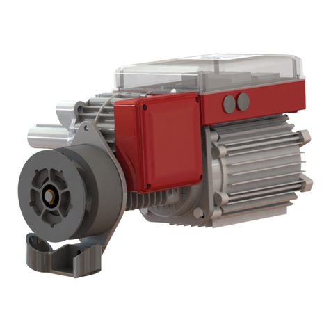
Grifco DRIVE User manual

Chamberlain Australia Pty Ltd
Unit 1, 75 Epping Rd
North Ryde NSW 2113
Ph: 1800 GRIFCO
www.grifco.com.au
Ref: D-M-DDO-001-D
Installation and User Manual for D-Drive Chain Drive Door Operator
This manual should be read in conjunction with Installation Manual
D-Drive Wall Controller manual (PART 2 OF 2)
Chain Drive Operator
INSTALLATION MANUAL
Chamberlain New Zealand Ltd
17B Arrenway Drive, Rosedale 0623
Auckland
Ph: 0800 653 667
www.grifco.co.nz
PART 1 OF 2

2
• If the supply cord is damaged, it must be replaced by the manufacturer, its service agent or similarly qualified persons in order to
avoid a hazard.
• Installation and wiring must be in compliance with your local building and electrical codes. Connect the power supply cord only to
properly earthed mains.
• Moisture and water can destroy the electronic components. Make sure under all circumstances that water moisture or storage
moisture cannot penetrate the electronics. The same applies for openings and cable entries.
• An electrician must disconnect electric power to the commercial door operator before making repairs or removing covers.
WARNING
Electrical
SAFETY INSTRUCTIONS
WARNING: THESE ARE IMPORTANT SAFETY INSTRUCTIONS.
FOLLOW ALL INSTRUCTIONS AS INCORRECT INSTALLATION CAN LEAD TO SEVERE INJURY OR DEATH
SAVE these instructions
This commercial roller door operator has been designed and tested to offer safe service provided it is installed, operated, maintained
and tested in strict accordance with the instructions and warnings contained in this manual.
• Sticking or binding doors must be repaired. Commercial doors, brackets and their hardware are under extreme tension and can
cause serious personal injury. Do not attempt to loosen, move or adjust them. Call for commercial door service.
• Do not wear rings, watches or loose clothing while installing or servicing a commercial door operator.
• To avoid serious personal injury from entanglement, remove all ropes connected to the commercial door before installing the door
operator.
• After the installation a final test of the full function of the system and the full function of the safety devices must be done.
• When operating a biased-off switch, make sure that other persons are kept away.
• The operator cannot be used with a driven part incorporating a wicket door (unless the operator cannot be operated with the wicket
door open).
• Operator may become hot during operation. Appropriate clearance and/or shielding should be supplied by the installer to ensure
any cabling, wiring and/or other items cannot come in contact with the operator. If temperature rise exceeds 50°C all fixed wiring
insulation must be protected, for example, by insulating sleeving having an appropriate temperature rating.
• Do not allow children to play with operator wall controls or remote controls. Keep remote controls away from children.
• Permanently fasten all supplied labels adjacent to the wall control as a convenient reference and reminder of safe operating
procedures.
• Disengage all existing commercial door locks to avoid damage to commercial door. Install the wall control (or any additional push
buttons) in a location where the commercial door is visible during operation . Do not allow children to operate push button(s) or
remote transmitter(s). Serious personal injury from a closing commercial door may result from misuse of the operator.
• Activate operator only when the door is in full view, free of obstructions and operator is properly adjusted. No one should enter or
leave the building while the door is in motion.
• The actuating member of a biased-off switch is to be located within direct sight of the door but away from moving parts. Unless it is
key operated, it is to be installed at a minimum height of 1500mm and not accessible to the public.
• Make sure that people who install, maintain or operate the door follow these instructions. Keep these instructions in a safe place so
that you can refer to them quickly when you need to.
• This appliance is not intended for use by persons (including children) with reduced physical, sensory or mental capabilities, or lack
of experience and knowledge, unless they have been given supervision or instruction concerning use of the appliance by a person
responsible for their safety. Children should be supervised to ensure that they do not play with the appliance.
• Use the operator for its intended purpose. The operator is designed lifting non-spring-balanced roller doors.
• Automatic Drive - Keep away from the area of the door as it may operate unexpectedly.
• Ensure that entrapment when operating the door in the open direction is avoided.
• This product is for indoor use only.
• If the operator is installed at a height less than 2.5 metres from floor level or any other level from which the operator can be
accessed (eg mezzanine) the installer is responsible to fit guards as appropriate to prevent access to moving mechanisms to
reduce risk of entrapment.
When you see this Safety Symbol and Signal Words on the following pages, they will alert
you to the possibility of serious injury or death if you do not comply with the warnings that
accompany them. The hazard may come from electric shock.
WARNING
Mechanical
When you see this Safety Symbol and Signal Words on the following pages, they will alert
you to the possibility of serious injury or death if you do not comply with the warnings that
accompany them. The hazard may come from something mechanical.
CAUTION When you see this Signal Word on the following pages, it will alert you to the possibility of
damage to your commercial door and/or the commercial door operator if you do not comply
with the cautionary statements that accompany it.

3
INTRODUCTION ...............................................................................................................................4
......................................................................................................................................................... 4
............................................................................................................................. 5
INSTALLATION.................................................................................................................................6
.................................................................................................................................................... 6
...................................................................................................................................................... 7
...................................................................................................................................................................... 9
.................................................................................................................................. 11
OPERATION....................................................................................................................................12
................................................................................................................................................................. 12
.............................................................................................................................. 13
SPECIFICATION .............................................................................................................................13
.................................................................................................................................................................... 13
.............................................................................................................................................................. 15
.................................................................................................................................................. 17
MAINTENANCE...............................................................................................................................18
WARRANTY.....................................................................................................................................19
NOTES .............................................................................................................................................21
CONTENTS

4
INTRODUCTION
The D-Drive Chain Drive Operator is designed to automate Non-Spring Balanced Roller Shutters.
This document outlines the specification and mechanical installation details of the Chain Drive Operator (including Safety Brake
device). It does not include details for the installation of the Wall Control, electrical connection, operation instructions, or door
installation details. For these details, please refer to the supplied Grifco Wall Control manual.
For details of door installation refer to the installation guide supplied by the door manufacturer.
Please use the table below to ensure the correct Chain Drive Operator for the correct Wall Control.
Operator and Wall Control
System Operator Wall Control Fastener Kit
GCD-45-23-SS GCDO-45-23 DDC-22 DDMB02: M16 KIT
GCD-22-23-VS GCDO-22-23 DDI-12 DDMB01: M12 KIT
GCD-45-23-VS GCDO-45-23 DDI-15 DDMB02: M16 KIT
Bearing
Mounting
Platform
Opener Mounting
Plate
Motor
Hand
Chain
Chain Drive
Gearbox
Hand Chain
Engagement
Mechanism
Limit Switch
Assembly
Wall Control
Grifco D-Drive Operator Part Number Nomenclature
SYSTEM OVERVIEW

5
PARTS QTY NOTES CHECK
Operator 1Use Operator selection table above to ensure correct Operator is supplied. Check
Drum Shaft diameter matches the Operator hollow shaft drive.
Mounting Brackets 2Use Mounting Bracket selection table to ensure correct Brackets are supplied
Bearing 1Ensure correct Bearing is supplied and internal diameter matches the Drum shaft
diameter
Drive Sprocket 1Ensure the correct drive sprocket is supplied with the internal diameter matching
the Drive Shaft diameter
Drive Chain 1Ensure the correct gauge Drive Chain is supplied to match the Plate Wheel and
Drive Sprocket
Hand Chain kit 1Ensure correct length of chain is supplied for the application
Manual Chain Engaging
Cord kit
1Ensure the correct length of Cord is supplied for the application
Encoder/Internal
Solenoid Brake Cable
1Ensure the correct length of electrical cable is supplied for the application.
Note: The encoder/internal solenoid brake cable is supplied connected to the
Operator connector box and is ready to connect to the Grifco Wall Control unit. Do
not attempt to disconnect cable from the Operator.
Motor Cable 1Ensure the correct length of electrical cable is supplied for the application.
Note: For contactor controller installation, motor cable is not supplied.
Fastener kit 1Ensure fastener kit is supplied
Safety Brake 1Ensure the correct safety brake has been supplied for the Chain Drive Operator
INTRODUCTION
PARTS FOR INSTALLATION CHECKLIST

6
INSTALLATION
• Mark the wall with bracket positions as defined by the door
manufacturer.
NOTE: The Operator is not handed; it can be
positioned on either side of a door that best suits the
application and available side-room.
See Operator installation section for changing the
hand chain side.
• Ensure the bracket heights are correctly set to allow for the
different centre heights of the brake and the Bearing.
Bracket width
Drum centre line
X
Safety Brake
Centre Height
Safety Brake
models
Safety Brake
Centre height
"X"
GSB-547
118 mm 69 mm
GSB-1017
150 mm 93 mm
GSB-1892
180 mm 104 mm
• Attach the brackets onto the wall using ALL available
mounting holes (Mounting fasteners are not provided.)
NOTE: Method of bracket installation is dependent on
the building structure and must be suitably
engineered to ensure robust and safe installation.
Safety
Brake
Models
Safety Brake
Centreline
Height
‘X’
GSB-547 118mm 69mm
GSB-1017 150mm 93mm
GSB-1892 180mm 104mm
(40mm bearing centre height: 49mm)
(50mm bearing centre height: 57mm)
(65mm bearing centre height: 76mm)
MOUNTING PLATFORM

7
INSTALLATION
• Slide the retaining ring over the drum shaft.
• Slide the Bearing onto the shaft.
• Mount the bearing onto the mount bracket.
Weld the retaining ring into position to prevent axial float
NOTE: Bearing to have correct orientation as shown.
(bearing collar to be inside)
WARNING
Mechanical
A SAFETY BRAKE MUST BE INSTALLED TO
PREVENT DOOR FROM FALLING IN THE EVENT
OF A MECHANICAL MALFUNCTION
• Insert the brake shaft key into the drum shaft.
• Slide the retaining ring over the drum shaft
• Slide the safety brake onto the drum shaft.
• Mount the safety brake onto the mount bracket
• Weld the retaining ring into position to prevent axial float
NOTE: BOLT TORQUE VALUES
Bolt Size Tightening Torque
M12 50 Nm
M16 70 Nm
M20 110 Nm
BRAKE BEARING

8
INSTALLATION
• Adjust the position of the brake and Bearing away from the
wall (X) as defined by the door manufacturer.
NOTE: The Safety Brake is supplied with a cable for
connection to the Operator controls. This cable is
connected to a switch on the Safety Brake that is triggered
in the event of a mechanical malfunction, causing the door
to drop.
Safety Brake and Operator Pairing
• Ensure the correct safety brake is used with the correct
operator.
• Safety Brake switch to be connected in accordance with
Wall Control manual
X X
Operator Safety Brake
GCDO-22-23 GSB-547
GCDO-22-23 /
GCDO-45-23
GSB-1017
GCDO-45-23 GSB-1892
12
3,3
5
118
227
253
218
280
68
245
50
Ø
40
Ø
18
GGSSBB--554477 SSaaffeettyy BBrraakkee DDiimmeennssiioonnss
GGSSBB--11001177 SSaaffeettyy BBrraakkee DDiimmeennssiioonnss
150
285
340
5
268
78
14
3,6
298
55
300
Ø 22
Ø
50
GGSSBB--11889922 SSaaffeettyy BBrraakkee DDiimmeennssiioonnss
4,4
18
15
330
180
300
90
390
94
351
340
Ø
65
Ø
22

9
INSTALLATION
CHANGE THE SIDE OF THE HAND CHAIN
ASSEMBLY:
NOTE: ONLY PERFORM THIS STEP IF REQUIRED
• Remove 4 bolts fixing the assembly to the back of the
motor.
• Rotate the assembly 180 degrees and replace bolts.
• Rotate the hand chain guide piece and pull cord housing to
re-align in the down position
LIFTING POINTS
• Use sling as shown for all models.
WARNING
Mechanical
OPERATORS ARE HEAVY.
TAKE CARE WHEN LIFTING.
OPERATOR

10
• Mount operator to the wall.
• Ensure mounting specification to the wall structure is
correctly engineered
• Fit drive sprocket onto gearbox stub shaft ensuring
alignment with the drum plate wheel
• Tighten sprocket grub screws
• Fit drive chain and cut length to suit.
• Ensure chain is aligned with drive sprocket and plate wheel
• Set chain tension by adjusting screws on the gearbox
bracket assembly
• Fit supplied hand chain over the chain wheel and through
the chain guide holes
• Link the chain together using the supplied chain link
• Ensure drive sprocket offset does not exceed dimension
specified.
Note: Ensure hand chain is untangled and un-twisted
before joining.
Hand Chain should be kept out of the way when not
in use through the supplied wall mounted keeper.
35 Max
INSTALLATION

11
INSTALLATION
• Take the supplied Manual Chain Engaging Cord and cut to
the required lengths so that ends are accessible from the
ground.
• Tie each length to the cable loops extending from the
emergency switch.
• Connect the RED and GREEN plastic pull-cord ends.
NOTE:
RED cord is for switching Operator OFF and
engaging Hand Chain.
GREEN cord is for switching Operator ON and
disengaging Hand Chain.
Check the function of each cable loop before
attaching the coloured plastic ends.
INSTALLATION OF THE BRAKE RELEASE CORD
The Brake Release Cord is used to release the
motor brake during manual operation. If the
motor brake is not released, extra effort is
required to manually move the door.
• Screw the provided Brake Handle into the brake actuator
(horse shoe shape)
• Tie the release cord to the Brake Handle and hang to the
rear of the drive as shown
• Ensure the brake release cord is suitably retained to the
wall to ensure no risk of entanglement with other
equipment, moving objects or persons
Brake release
handle and cord
Green
Red
MANUAL CHAIN ENGAGING CORD

12
OPERATION
Engaging the Hand Chain:
POWER OFF OPERATOR
• Gently pull the cord with the RED handle downwards as far
as possible. The control voltage will be interrupted and the
door can no longer be operated electrically.
• Release the hand chain from its wall keeper.
• Move the door in the OPEN or CLOSE direction by pulling
on the hand chain.
Disengaging the Hand Chain:
POWER ON OPERATOR
• Gently pull the cord with the GREEN handle downwards as
far as possible. The control voltage will be switched on
again and the door can be operated electrically.
• Attach the emergency hand chain to its wall keeper.
NOTE: When not in use, ensure chain, cables,
and cords are securely attached to wall to avoid
the risk of pedestrian and vehicular
entanglement.
NOTE: To reduce load on the hand chain, the
brake may need to be released if applicable. Refer
to the next step.
OPERATION OF BRAKE RELEASE CORD
• Before operating the door via hand chain, pull the brake
release cord firmly, and tie off to a suitable cleat or fixed
point.
WARNING
Mechanical
Ensure the brake release cord is not pulling
on the motor brake, and thus the motor
brake is properly engaged with the motor
shaft before operating electrically.
HAND CHAIN

13
SPECIFICATION
GCDO-22-23 GCDO-45-23
Type Chain Chain
Starting Torque Nm 220 450
Run Torque Nm 180 400
Speed rpm 23 23
Manual operation Chain Chain
Power kW 1 1.5
Voltage V 3~230 3~230/400
Current A 4 9.0/5.2
Cycles/ hr @ max. shaft revs 8 8
Max Output Shaft revs 40 40
Output Shaft Dia mm 40 40
Op Temp °C +5, +40 +5, +40
Weight kg 31 47
Solenoid Brake Yes Yes
Safety Brake Separate device Separate device
Factory Motor winding connection Delta Star
(VFD only)
Gearbox size Size 3 Size 4
IP Rating IP20 IP20
Warning: Before resetting the safety brake ensure that the door has been serviced, inspected and is a compliant and safe installation.
1. Using the mechanical hauling chain on the operator, rotate the Curtain Drum by at least one quarter of a revolution in the
upwards direction.
2. Loosen the bolts as indicated (without removing the
nuts) to release the locking plate of the brake:
3. Rotate the locking plate in the direction indicated until the
microswitch roller leaver is disengaged and sits freely in
the locking plate cut-out (This may require some tapping
of the locking plate with a mallet).
4. Secure the locking plate bolts released in step 2 ensuring
the following torque settings are applied:
For GSB-547 = 30 Nm
For GSB-1017 = 60 Nm
For GSB-1892 = 50 Nm
5. Re-engage the operator and test the door is free to move in both the upwards and downwards direction until the limits are
reached at least 3 times.
HHooww ttoo rreesseett tthhee ssaaffeettyy bbrraakkee
Warning: Before resetting the safety brake ensure that the door has been
serviced, inspected and is a compliant and safe installation.
1. Using the mechanical hauling chain on the operator, rotate the
Curtain Drum by at least one quarter of a revolution in the upwards
direction.
2. Loosen the bolts as indicated (without removing the nuts) to release
the locking plate of the brake:
3. Rotate the locking plate in the direction indicated until the
microswitch roller leaver is disengaged and sits freely in the locking
plate cut-out (This may require some tapping of the locking plate
with a mallet).
4. Secure the locking plate bolts released in step 2 ensuring the
following torque settings are applied:
For TS3 = 30 Nm
For TS4 = 60 Nm
For TS5 = 50 Nm
5. Re-engage the operator and test the door is free to move in both the
upwards and downwards direction until the limits are reached at least
3 times.
The microswitch roller must
be disengaged from the
switch and sit in the locking
plate cut out.
OPERATION
HOW TO RESET THE SAFETY BRAKE
OPERATOR
HHooww ttoo rreesseett tthhee ssaaffeettyy bbrraakkee
Warning: Before resetting the safety brake ensure that the door has been
serviced, inspected and is a compliant and safe installation.
1. Using the mechanical hauling chain on the operator, rotate the
Curtain Drum by at least one quarter of a revolution in the upwards
direction.
2. Loosen the bolts as indicated (without removing the nuts) to release
the locking plate of the brake:
3. Rotate the locking plate in the direction indicated until the
microswitch roller leaver is disengaged and sits freely in the locking
plate cut-out (This may require some tapping of the locking plate
with a mallet).
4. Secure the locking plate bolts released in step 2 ensuring the
following torque settings are applied:
For TS3 = 30 Nm
For TS4 = 60 Nm
For TS5 = 50 Nm
5. Re-engage the operator and test the door is free to move in both the
upwards and downwards direction until the limits are reached at least
3 times.
The microswitch roller must
be disengaged from the
switch and sit in the locking
plate cut out.
The microswitch roller must
be disengaged from the
switch and sit in the locking
plate cut out.

14
SPECIFICATION
15141312111098765432
15141312111098765432
H
G
F
E
D
C
B
A
16
H
G
F
E
D
C
B
A
1
1
Tornado Antriebstechnik GmbH, Flohrstr. 33, 13507 Berlin
1 /
Sheet
Weight
Name
Date
Revision
No.
Chkd.
Apvd.
Drawn
NameDate
Surface
texture
according to
ISO 1302
General tolerance:
DIN ISO
2768-vK
Scale
The reproduction, distribution and
utilization of this document as well
as the communication of its
contens to other without express
authorization is prohibited.
Offenders will be held liable for the
payment of damages. All rights
reserved in the event of the grant
of a patent, utility modell or design.
Material
Titel
Drawing no.
Resp. Department
Lang. en
Document Status
Document Typ
Repl. by.:Repl. f.:
Origin
MB
Free
Construct.
MB-TA000486
1:2 (1:1 ; 1:5)
RDA-220.13-KE-DCO-20-40-F
20.11.2020 JE
Z
detail Z
1:1
120
1:5
Bemaßung Passung Höchstmaß Mindestmaß
40 H8 40,03940,000
12 E8 12,05912,032
13
120
104
343
209
O90
11775
84 323 78
223120
100100
135
270
141
580
8095
107
104
O
40H
8
43,3
+0,2
0
12 E8
134
147O
40
GCDO-22-23
15141312111098765432
15141312111098765432
H
G
F
E
D
C
B
A
16
H
G
F
E
D
C
B
A
1
1
Tornado Antriebstechnik GmbH, Flohrstr. 33, 13507 Berlin
1 /
Sheet
Weight
Name
Date
Revision
No.
Chkd.
Apvd.
Drawn
NameDate
Surface
texture
according to
ISO 1302
General tolerance:
DIN ISO
2768-vK
Scale
The reproduction, distribution and
utilization of this document as well
as the communication of its
contens to other without express
authorization is prohibited.
Offenders will be held liable for the
payment of damages. All rights
reserved in the event of the grant
of a patent, utility modell or design.
Material
Titel
Drawing no.
Resp. Department
Lang. en
Document Status
Document Typ
Repl. by.:Repl. f.:
Origin
MB
Free
Construct.
MB-TA000493
1:2 (1:5)
CD-450.23-KM-DC-40-C40
16.11.2020 JE
109
205
O
1:5
Bemaßung Passung Höchstmaß Mindestmaß
40 h1040,00039,900
255,5
89,5
175
O
120
160
O
210
235
326
402,5 122
129148
115
255
277
30
clamping range 30
clamping range
159 159
187,5
375
113
108
210
170
10
13,5
751
318
40 h10
shaft-kit
mountable on both sides
key A12x8x60
80
50
GCDO-45-23
OPERATOR

15
SPECIFICATION
GSB-547 GSB-1017 GSB-1892
Permissible torque Nm 547 1017 1892
Maximum safety catch torque Nm 2058 3509 8230
Maximum operating speed min -1 20 18 12
Test certificate number Door FV 3 / 014 Door FV 3 / 015 Door FV 3 / 016
Shaft mounting mm 40 50 65
Bearing type Self-aligning bearing Self-aligning bearing Fixed bearing
Unit weight kg 12.5 21.0 34.0
Drum Diameter (mm) Max. Door Weight in Kg
165 450 997 1990
168 442 979 1954
219 355 800 1499
273 283 635 1217
SAFETY BRAKE

16
SPECIFICATION
GSB-547
SAFETY BRAKE CONTINUED
GSB-1017
www.mfz-antriebe.de
Fangvorrichtungen für Rolltore
TS 4
Abmessungen Fangvorrichtungen.
150
285
340
5
268
78
14
3,6
298
55
300
X
Ø
22
Ø
50
Ansicht: X
View: X
4,4
18
15
330
180
300
90
390
94
351
340
X
Ø
65
Ø
22
GSB-1892

17
SPECIFICATION
E
C
B
G
F
P
A
O
M
L
D
Q
H
T
V
U
R
S
I
K
J
N
D
M
P
DDMP-01
B
C
E
F
G
H
L
I
A
D
M
O
J
K
N
Model
A
B
C
D
E
F
G
H
I
J
K
L
M
N
O
Load
Capacity
Weight
DDMP-02
559 464 168 6 78 90 18 110 132 22 450 38 64 59 100 7000 16
Units
mm mm mm mm mm mm mm mm mm mm mm mm mm mm mm
kg kg
The maximum load each bracket can support is the ‘Load capacity’.
The calculation of determining the weight on each bracket must
factor in the weight of the drum, the roller shutter curtain, the
Operator and the dynamic forces of stopping and starting the door.
CAUTION
MOUNTING PLATFORM

18
MAINTENANCE
Frequently examine the installation for instability, signs of wear or damage to cables, and mounting. Do not use if repair or adjustment
is necessary. Power must be turned off before servicing, cleaning or adjusting the operator.
Certain mechanical aspects of the installation as applicable must be checked, see below:
Monthly
Quarterly
* SERVICE MUST BE CARRIED OUT BY A QUALIFIED TECHNICIAN
Refer to the Wall Control manual for further information regarding maintenance and maintenance schedules.

19
WARRANTY
NOTE: Refer to D-M-ACG-100 GRIFCO D-Drive Wall Control Instruction manual for Cycle-Count warranty conditions.
1. Your consumer rights and guarantees
This Limited Warranty is provided by Chamberlain Australia Pty Ltd.
Chamberlain New Zealand Limited (Chamberlain), contact details in Section 5
below. This Limited Warranty applies to a Grifco® Commercial unit (Unit)
purchased in Australia and New Zealand, and gives you benefits which are in
addition to your consumer rights and remedies under the Australian
Consumer Law (or corresponding New Zealand consumer protection laws).
You can find out more information about your consumer rights and
guarantees which the law provides in Australia at www.accc.gov.au. in New
Zealand at www.consumerprotection.govt.nz. We also provide this
statement as required under the Australian Consumer Law:
Our goods come with guarantees that cannot be excluded under the
Australian Consumer Law. You are entitled to a replacement or refund for
a major failure and for compensation for any other reasonably foreseeable
loss or damage. You are also entitled to have the goods repaired or
replaced if the goods fail to be of acceptable quality and the failure does
not amount to a major failure.
2. What does our Limited Warranty cover?
Chamberlain warrants that, when purchased new in Australia or New
Zealand. the Unit (all parts of the Unit other than globes and batteries) is free
from defects in materials and workmanship (Limited Warranty) for the Limited
Warranty period. subject to the terms and conditions of this Limited Warranty.
The Limited Warranty period (for Accessories see below) is 2 years (24
months) from the date of purchase or when a recommended cycle count for
the purchased operator has been reached (which ever comes first)
The Limited Warranty period for remote controlled transmitters and
accessories included with the Unit (Accessories) is 12 months from the date
of purchase.
The Limited Warranty for genuine spare parts is free from defects in material
and workmanship for a period of 6 months from date of purchase.
3. Limited Warranty Conditions
The following terms and conditions apply to your Limited Warranty:
our Limited Warranty is effective from date of purchase as indicated in
Section 2 above;
proof of purchase of the Unit is required;
Please also see the User Manual for the Unit available on our website. or
provided at the time of purchase.
4. What is not covered
Batteries and globes are not covered under the Chamberlain Limited
Warranty
Travel costs incurred by Chamberlain or its authorised dealer in either
travelling to and from areas outside a capital city area. These costs will be at
the purchaser's expense.
Additional access costs incurred by Chamberlain or its authorised dealer in
obtaining access to premises where the Unit is not readily accessible. These
costs will be at the purchaser's expense.
Our Limited Warranty covers defects as explained, and does not cover all
problems and mishaps that may occur in relation to the Unit including:
you got what you asked for but simply changed your mind, found it cheaper
somewhere else, decided you did not like the purchase or had no use for
it; you misused the Unit in any way that caused the problem;
you knew of or were made aware of any deficiencies with the Unit before
date of purchase:
use of the Unit with controls or third party devices or software which has
not been supplied. or pre-approved, by Chamberlain;
problems relating to or residing in third party hardware, software or other
items with which our product is used;
any loss of data related to you or provided by you. or loss related to
downtime associated with use of the product whether through power
outage, failure of internet or wireless connectivity, network disruptions. or
otherwise;
non-compliance with the relevant instructions in the User Manual;
tampering, neglect abuse, wear and tear, accident, electrical storm,
excessive use or conditions other than normal use;
problems with, or relating to, hardware, including but not limited to the
springs. hinges. guides:
problems caused by electrical faults or replacement of batteries or light
bulbs, blown fuses, electrical surges, power surges or power strikes. fire,
flood, rain, water, lightning or storms;
water or moisture ingress that causes corrosion or electrical malfunction;
corrosion caused by sea air if located near a waterway, beach etc: lack of
proper maintenance, service or care of the Unit; and/or
damage caused by insects, pests or other after sale damage caused by
events or accidents outside Chamberlain's reasonable control and not arising
under normal and standard operating conditions.
5. Where you need help with our product
If you have a problem with the Unit or if you are concerned it may be
defective, please contact our Customer Service team below:
Australia Phone toll free 1800 474 326
Fax toll free 1800888121
Address Unit 1. 75 Epping Road North Ryde, NSW 2113
Website https://www.grifco.com.au/
New Zealand Phone toll free 0800 653 667
Auckland Phone 09 477 2823
Fax toll free 0800653 663
Website https://www.grifco.co.nz/
As a first step, our Customer Service team will provide product support
assistance to help you try to resolve the problem and in some cases.
replacement parts for "do it yourself repairs·. If our technical team need
to see the product to determine the nature of the fault we will arrange an
inspection by an trained technician, or ask that you send the product to us.
If your product was installed at your premises by an authorised dealer,
please contact the installer indicated in your sales documents for prompt
on-site service. or consult our Customer Service team if you need help in
finding a local service technician. A service fee for on-site service may
apply.
Authorisation from Chamberlain is required for warranty service under this
Limited Warranty.
6. Delivery Charges
If an inspection is required in order to determine the nature of the fault
please send the Unit freight paid and well packaged in accordance with our
instructions. Any costs associated with transporting the Unit will be at
Chamberlain's cost if the Unit has breached a statutory consumer
guarantee. Repairs and replacement parts provided under this Limited
Warranty are free of charge (and repaired items or replacement parts for
Units found to be defective will be returned to you at our cost), and
warranted by Chamberlain for the remaining portion of the original warranty
period. However. if you make a claim under this Limited Warranty. and this
Limited Warranty does not apply, or if the law does not provide you with a
statutory right or remedy as a consumer, you may be required to pay labour,
assessment and/or freight costs and delivery charges to repair, replace and/
or return the Unit to you.
7. How to register your product
Please register your Unit and contact details at this link
https://www.grifco.corn.au/warranty-registration. so that we or your
authorised installer can locate your details and provide you with product
support assistance as quickly as possible, and keep you up to date with
product updates. Registration can also be done by contacting Chamberlain
Customer Service.
8. Important Reminder
All other guarantees (other than your statutory rights and guarantees as a
consumer under applicable laws) are excluded to the fullest extent that we
may lawfully do so. Unless the law requires us to do so. we do not accept
any other liability, such as compensation for damages, injury or loss.
Last updated; 21st April 2022
CHAMBERLAIN WARRANTY
Limited Warranty in Australia and New Zealand
Table of contents
Other Grifco Door Opening System manuals
Popular Door Opening System manuals by other brands

Assa Abloy
Assa Abloy Sargent 1331 manual

International Door Closers
International Door Closers ADJUSTABLE POWER D300 Series Installation instruction

Assa Abloy
Assa Abloy Corbin Russwin PED5800 Series installation instructions

Genius
Genius COMPAS 24C installation guide

Genius
Genius MIDEL22 installation instructions

ADL
ADL M04 Assembling instructions

Aluprof
Aluprof AL-BR01 Installation, Assembly and Operating Manual

Von Duprin
Von Duprin 33A Series installation instructions

Chamberlain
Chamberlain ATS 2113X 1/2 HP installation manual

Johnson Controls
Johnson Controls PGP303 installation guide

Aumuller
Aumuller FTA600 R Assembly and commissioning instructions

elock
elock KC1005-4 BW manual