LCN 4840 User manual

*25381*
25381
1 General Information
This door operator requires these additional system components:
7900 or 7980 series Control Box
• 459 Pnuematic Door Loop Kit, (4 1/2 “ maximum reveal depth, see page 6) or
• 460 Pnuematic Transfer Hinge Kit (see page 6)
Push & Pull side actuator devices (switches)
LNOTE: 460 Transfer Hinge requires an interior door raceway between transfer hinge and 4840 Auto - Equalizer®
Requirements:
Minimum door width is 24”
Minimum door top rail is 4 1/2”
Minimum stop width is 1”
Flush or single rabbeted frames require a - 418 FPA
Arm Options:
EDA (standard), Cush N Stop or Spring Cush
Non-Handed/Non-Sized/Low Energy
Installation And Adjustment Of Door Operator
4840 Auto-Equalizer
Installation Instructions
Left
Hand
Door
Right
Hand
Door
Left Hand Installation Shown
How To Tell Hand Of Door
CAUTION
Improper installation or regulation may result in personal
injury or property damage. Follow all instructions
carefully. For questions, call LCN at
877 - 671 - 7011

Standoff
Mounting
Plate
30°
Main Arm
30°
Approx.
Figure 1
Figure 2
2 Operator Installation
LNOTE: If using the 460 transfer hinge, install at this time. See page 6 for details.
2a Prepare door & frame per template on page 7. Drill and/or tap holes to receive 1/4 - 20 machine screws or No. 14
wood screws. Use fasteners provided by LCN to keep warranty valid.
2b Remove operator assembly from mounting plate, as shown in Figure 1 above. Install mounting plate on door using
(6) 1/4 - 20 x 5/8” machine screws or (6) No. 14 x 1 1/2” wood screws provided. Reattach operator assembly.
2c Place arm on the top of closer shaft with main arm parallel to the door. Place wrench on the bottom of the closer shaft
and rotate toward hinge approx. 30°. See Figure 2. Main arm can now be placed on to closer shaft. Secure with arm
screw.
LNOTE: If installed properly, main arm will rest against door.
2d Swing door open about 45°. Using the fasteners provided, mount shoe to frame stop per proper templating on page 7.
Be sure to install the “fth” screw. If stop is not wide enough, use spacer block provided or cush shoe support shown
on page 7.
2e Connect air line to air inlet tting, then feed other end toward control box by either using the 15” pneumatic door loop
or the pneumatic transfer hinge (see page 6).
Standoff
Mounting
Plate
30°
Main Arm
30°
Approx.
Figure 1
Figure 2

3 Closing Force Adjustment (see Figure 3)
3a To adjust Closing Force, turn the spring adjustment
nut clockwise or counter-clockwise the required
number of turns to match the door width in Tables 1 &
2. Maximum adjustment, 5 turns counterclockwise and
7 turns clockwise.
CAUTION
Do not set door speed faster than chart recommends.
4 Closing Speed Adjustment (See Figure 3)
4a THE 4840 SERIES CLOSER HAS BEEN
REGULATED PRIORTO SHIPMENT. If regulation
adjustments are needed use 3/32 Hex wrench
furnished, and refer below.
4b A “normal” closing time from 90° open position is 5 to
7 seconds, evenly divided between Main Speed and
Latch Speed.
4c To slow Main Speed of door, turn regulating screw
(nearest to arm) clockwise.
4d To slow Latch Speed of door, turn regulating screw
(nearest to latch) clockwise.
4e Do not allow door to slam into frame.
5 Backcheck Adjustment
5a Backcheck slows the door swing as it approaches full
opening (see Figure 3).
5b Increase the resistance of backcheck only if necessary
to prevent the door from striking a wall. To do this,
turn the regulating screw (nearest to hinge) clockwise
by quarter turns. DO NOT USE AN ABRUPT
BACKCHECK.
Table 1
Exterior Door
Maximum Door Width Number of Turns
30” 0 Turns
36” 2 Turns C.W.
42” 7 Turns C.W.
Table 2
Interior Door
Maximum Door Width Number of Turns
34” 5 Turns C.C.W.
38” 0 Turns
48” 2 Turns C.W.
54” 7 Turns C.W.
FIGURE 3
.
LATCH SPEED
MAIN SPEED
BACKCHECK
SPRING
ADJUSTMENT NUT
INCREASE
FORCE
DECREASE
FORCE

6 Opening Speed Adjustment
LNOTE: For air pressure regulation, see control box instructions.
6a The door opening speed must be adjusted to suit the width and weight of door. The wider and / or heavier the door,
the slower it should open. To determine opening speed, measure door width and weight and set speed to open door
from 0° to 80° for the time shown in Table 3 below. The opening speed control adjusting screw is located in the end
of the door operator near the tubing connection (see Figure 4). Using a 3/32” hex wrench (provided), turn the speed
control clockwise to slow the door, counterclockwise to increase door speed.
Opening
Speed Control
Adjusting Screw
(Socket Head Regulating Screw)
Operator
Model No.
Figure 4
Table 3
Door Weight
in Pounds
Fastest Opening Time in Seconds to 80°
Position
Door Width in Inches
36” 42” 48”
100 lbs. 3.0 sec. 3.0 sec. 3.0 sec.
125 lbs. 3.5 sec. 3.5 sec. 3.5 sec.
150 lbs. 3.5 sec. 3.5 sec. 3.5 sec.
200 lbs. 4.0 sec. 4.0 sec. 4.0 sec.
LNOTE: If door width or weight is between the sizes and pounds listed, use the time shown for the next wider or heavier
door.
6b If door weight cannot be measured, the weight can be estimated by nding the area of the door (length x width) and
multiplying it by the weight per square foot for the door type that is being used, as shown in Table 4 below.
Table 4
Door Type Weight per Sq. Ft.
Solid Core Wood
20 Ga. Flush Hollow Metal
Aluminum x 1” Glass
5.5
Mineral Core Door
16 Ga. Flush Hollow Metal
Aluminum x 1” Glass
7.0

7 Delay Time Adjustment
After opening, the door should remain at the 90° position for no less than 5 seconds. This “Delay Time” can be increased to
approximately 30 seconds by turning the timer adjustment wheel(s) clockwise. For the location of this wheel(s), refer to 7900 or 7980
Series Control Box Instruction Sheet. Adjust “Delay Time” to maximum practical for the elderly or handicapped. Time cycle begins when
switch or scanner is activated.
8 Attach Cover
8a Slide cover insert into the bottom cutout in cover (see Figure 5).
8b Push cover over the operator assembly and against mounting plate.
8c Insert cover screws and tighten securely.
9 Locating the Caution/Automatic Door Decal
9a Locate one decal on each side of door near lock stile of door, approximately 18” min. to 42” max. above the oor. The
decal location must be visible without interference from door trim, panic devices, etc.
9b Clean a 6” x 6” area where decals will be placed.
9c Apply one decal (item 16 on page 10) on each side of the door. Remove backing and “roll” onto door to avoid
trapping air under decal.
Figure 5

Concealed or Surface Air Transfer Options
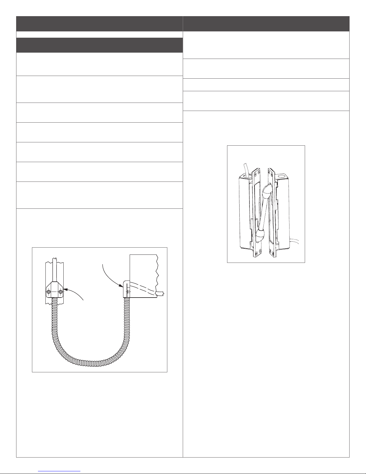
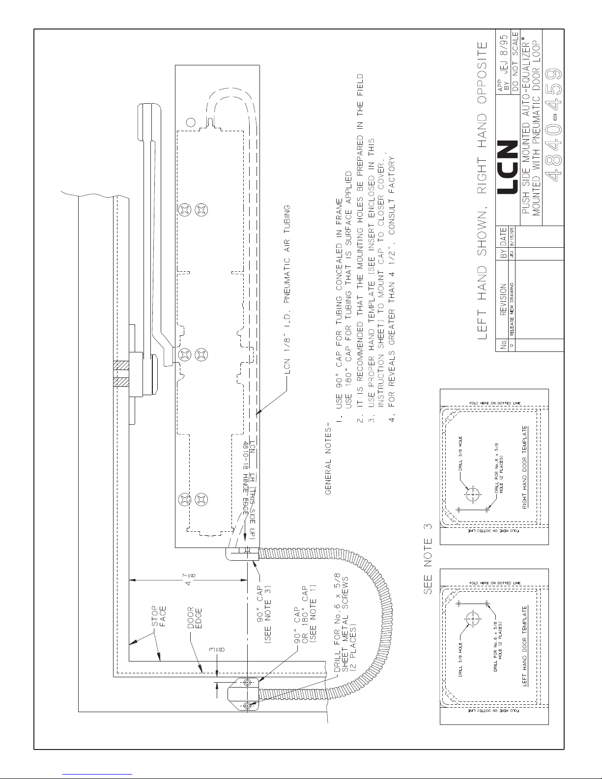
10 Pneumatic Door Loop Installation (see Figure 6)
LSee page 8 for template
LReveal must be less than 4 Z\x”
10a Remove the cover end cap (closest to hinge stile of
door) by removing the (2) Phillips head screws from
inside the cover.
10b Place the proper hand template (see cutouts on page
11) over the end cap and tape down securely.
10c Once the template is in place, drill (1) 3/8” hole, and
(2) 1/16” holes in the proper location.
10d After holes are drilled, remove template and place end
cap back on the cover.
10e Feed 1/4” tubing through the drilled end cap and also
through the 15” aluminum tubing supplied with kit.
10f Place 90° door loop cap on cover end cap (making
sure to line up slots over the ends of the 15” tubing)
and secure with No.6-32 screws provided.
10g Feed the 1/4” tubing (either 180° up the frame, or 90°
into the frame), place the concealed 90° or the surface
180° (depending on the installation) door loop cap
over end of the 15” aluminum tubing and secure to the
frame of the door. (See Figure 6).
Figure 6
Figure 7
90° Concealed
Cap Shown
180° Surface
Cap Shown
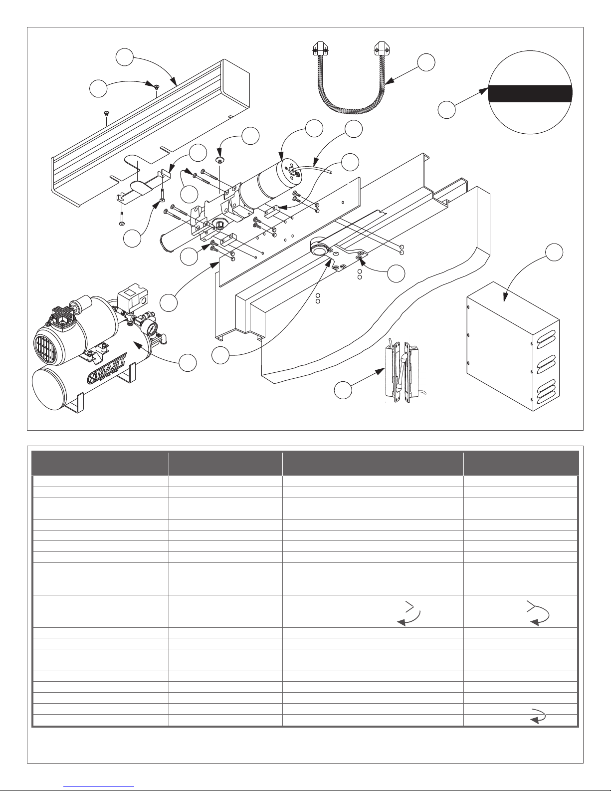
11 Pneumatic Transfer Hinge Installation (see Figure 7)
LA INTERIOR RACEWAY FROM TRANSFER HINGE TO 4840
CLOSER IS REQUIREDTO USE THIS PRODUCT, SEE PAGE
9 FOR TEMPLATE.
11a Apply pneumatic transfer hinge housing using No.
8-32 machine screws provided.
11b Connect tubing using the inline tubing splice provided
11c Apply transfer hinge unit using No.10-24 machine
screws provided.
11d Check operation of pneumatic transfer hinge unit.
LNOT FOR USE WITH SWING CLEAR HINGES OR CENTER
PIVOTS!
Figure 6
Figure 7
90° Concealed
Cap Shown
180° Surface
Cap Shown

21
2
®
1
NOISNEMIDDEXIF
MMA 06/06

4840-459
®

.AID"1
PEED"X
EMARFROF
URHT.AID
ERIWOT
LENNAHC
ROODROF
LATEM
EMARFROROOD
)WEIVEDIS(
DOOW
EMARFROROOD
)WEIVEDIS(
ROOD
)°081NEPO(
EMARF
:DOOW
PERPSELOH DERA
TSNIGNIRUD .LLA
:LATEM
DEPPAT42-01#
)SCLP21(ELOH
OLEB"6DEDNEMMOCER W
EGNIHREPPU
11
1
11
32
8
9
7
TNEMECROFNIER
).AG61("060.
MUMINIM
.NIM
7
8
EDISTUOMORF
ROODFOECAF
3
.XAM
TSNINEHW DELLA
C
L
C
L
C
L
NGILATSUMEMARFNITPEFO
.ROODNITPEFOHTIW
C
L
2
RTSNIROFDESIVER TEEHSNOITCU
MMA
89/02/1
21
32
3
81
16
3
8
AMUENP EGNIHREFSNARTCIT
OLLOHNI EMARFDNAROODLATEMW
4840-460
ELACSTONOD
PPA
YB
90/9FRK
1
ARDER DACNONW
JEJ
DYBNOISIVER.oN ETA
59/1/8
®
3
FEDISTUOMORF8/7 ROODFOECA
TDJ
90/71/9

Item No. Part No. Description Quantity
1 925 1/8 “ I.D. Pneumatic Tubing 5’ or 12’ Section
2 4810-18 Standard Mounting Plate 1
3No. 14 x 1 1/2”
1/4-20 x 5/8”
Phillips Head Wood Screw or
Phillips Head Machine Screw 6
4 4810-182 Standoff 2
5 4840-3071 LCN Switch-Actuated Auto Equalizer 1
6 1/4-20 x 2 1/2” Phillips Head Machine 4
7 4810-159 Arm Shaft S 1
8
4040SC-3035
4040EDA-3035
4040CNS-3035G
Spring Cush Arm Assy.
Extra Duty Parallel Arm Assy.
Nonhanded Cush-N-Stop Assy.
1
9
1/4-20 x 5/8”
1/4-20 x 1 1/2”
No.14 x 2 “
Phillips Head Machine Screw
Phillips Head Wood Screw
4
1
5
10 4840-72 Cover 1
11 4840-163 Cover Insert 1
12 4810-31L Long Cover Screw 2
13 4810-31 Cover Screw 2
14 7900 or 7980 Control Box 1
15 920 Series Compressor (optional) 1
16 4820-155G Decal 2
17 4840-459 Pneumatic Door Loop Kit (optional) 1 or
18 4840-460 Pneumatic Transfer Hinge Kit (optional) 1
14
1
2
3
4
5
6
7
8
9
10
13
11
12
16
15
17
18
AUTOMATIC
DOOR
CAUTION
or

© Allegion 2014
Printed in U.S.A.
25381 Rev. 01/14-g
If the proper hand door has been determined, cut out the appropriate template and place on the end cap.
Customer Service
1-877-671-7011 www.allegion.com/us

Additional Notes: Revision History Revision Description:
G > Revised artwork
1. None G H J K L M
043812
Material
White Paper
Edited By Approved By EC Number Release Date
D. Myers M. Sasso 043812 01-01-14
Notes
1. printed two sides
2. 12-Page Saddle-Stitched booklet
3. printed black
4. tolerance ± .13
5. printed in country may vary
6. drawings not to scale
Title
4840 Series Instruction Manual
Creation Date
04-27-10
Number
25381
Revision
G
Created By
N/A Activity
3899 Hancock Expwy
Security, CO 80911 © Allegion 2014Software: InDesign CS6
17.00 8.500
11.000 11.000
BEGINNING SHEET FOLDED SHEET
FRONT FRONT
Other LCN Door Opening System manuals

LCN
LCN 1450 Series User manual

LCN
LCN 3030 Series User manual

LCN
LCN Benchmark III 9140 User manual

LCN
LCN 4020 Series User manual

LCN
LCN 1461 CUSH User manual

LCN
LCN 4310ME Series User manual

LCN
LCN 3130-SEL Sentronic User manual

LCN
LCN 4050 Series User manual

LCN
LCN 2210DPS Series User manual

LCN
LCN 4050 Series User manual

LCN
LCN Sentronic 2310-ME User manual

LCN
LCN 1450 Track Series User manual

LCN
LCN ST-2701 User manual

LCN
LCN ELECTRIC AUTO-EQUALIZER 4630 User manual

LCN
LCN 1261 CUSH User manual

LCN
LCN 4040XP User manual

LCN
LCN 2210DPS Series User manual

LCN
LCN 4050 Track Series User manual

LCN
LCN COMPACT 6400 Series User manual

LCN
LCN 3130 Series User manual