m-Dimension 12/400N User manual

ISO 9001:2008 Certified Company
Form 121114
Model:
12/400N
OWNERS MANUAL SEPTEMBER 2007
DC to AC Power Inverters
121114C
Manufacturer of DimensionsTM Inverters
4467 White Bear Parkway
St. Paul, MN 55110
Phone: 651-653-7000 Fax: 651-653-7600
E-mail: [email protected]
Web: www.dimensions.sensata.com

Page 2
OWNERS MANUAL
FOR SENSATA TECHNOLOGIES
DIMENSIONS INVERTERS
Model ADI-12/400N
Table of Contents
Page
1. General . . . . . . . . . . . . . 2
2. Description . . . . . . . . . . . 2
3. Installation . . . . . . . . . . . 2
4. Start Up/Operation . . . . . . 4
5. Troubleshooting . . . . . . . . 4
6. Installation Figure 1 . . . . . 5
7. Limited Warranty . . . . . . . 6
1. GENERAL
1.01Dimensions inverters have been designed
andmanufacturedformanyuserapplicationsand
long life. They utilize patented construction
methodsandhightechnologyelectronicpartsand
circuitry.
1.02
CAUTION:
Inverters produce hazardous
voltage. Toavoidriskofharmorfiretheunitmust
be properly installed. There are no user service-
able parts inside, do not remove the cover.
CAUTION:
Theinvertershouldnotbemountedin
a location that may be exposed to rain or spray.
CAUTION:
The inverter should not be installed in
a zero clearance enclosure.
CAUTION:
Damage to the inverter will occur if
correct polarity is not observed when installing
the DC input cables.
CAUTION:
Damage to the inverter will occur if an
externalACpowersourceisappliedtotheinverter’s
AC output or its hardwire output.
CAUTION:
The inverter contains a circuit breaker
and capacitor that may produce a spark. Do not
mount in a confined battery or gas compartment.
CAUTION:
Working in the vicinity of lead - acid
batteries is dangerous. Batteries generate explo-
sive gases during operation. There is a risk of acid
exposure. There is also a risk of high current
dischargefromshortingthebatterythatcancause
fire and explosion.
CAUTION:
Besuretheinverter'scircuitbreakeror
fuse are turned "OFF" during installation.
2. DESCRIPTION
2.01 The inverter converts 12 VDC to 120
VAC, 60 HZ, having a pure-sine wave form.
2.02 The inverter has a controlled frequency
at 60 HZ + 0.6Hz.
2.03
The inverter has internal protection
against output short circuit, output overload and
high temperature conditions. Also, there is a
thermally controlled cooling fan.
2.04 The inverter is designed to operate
any 120 VAC, 60 HZ, single phase appliance,
equipment or tool within its power ratings.
Inverter Rating
Model: 12/400N
Output Power (constant): 400 Watts
Output Current: Up to 3 Amps
Peak Output: 800 Watts
Input Current: Up to 40 Amps DC
Weight: 14 Lb
Size: 12.5" x 6" x 5"
3. INSTALLATION
3.01 The following instructions should be
thoroughly read and understood before installa-
tion.
3.02
CAUTION:
Inverters produce hazard-
ous voltages, to avoid risk of harm or fire the unit
must be properly installed.
CAUTION:
Damage to the inverter will occur if
correctpolarityisnotobservedwheninstallingthe
DC input cables.
CAUTION:
Damage to the inverter will occur if an

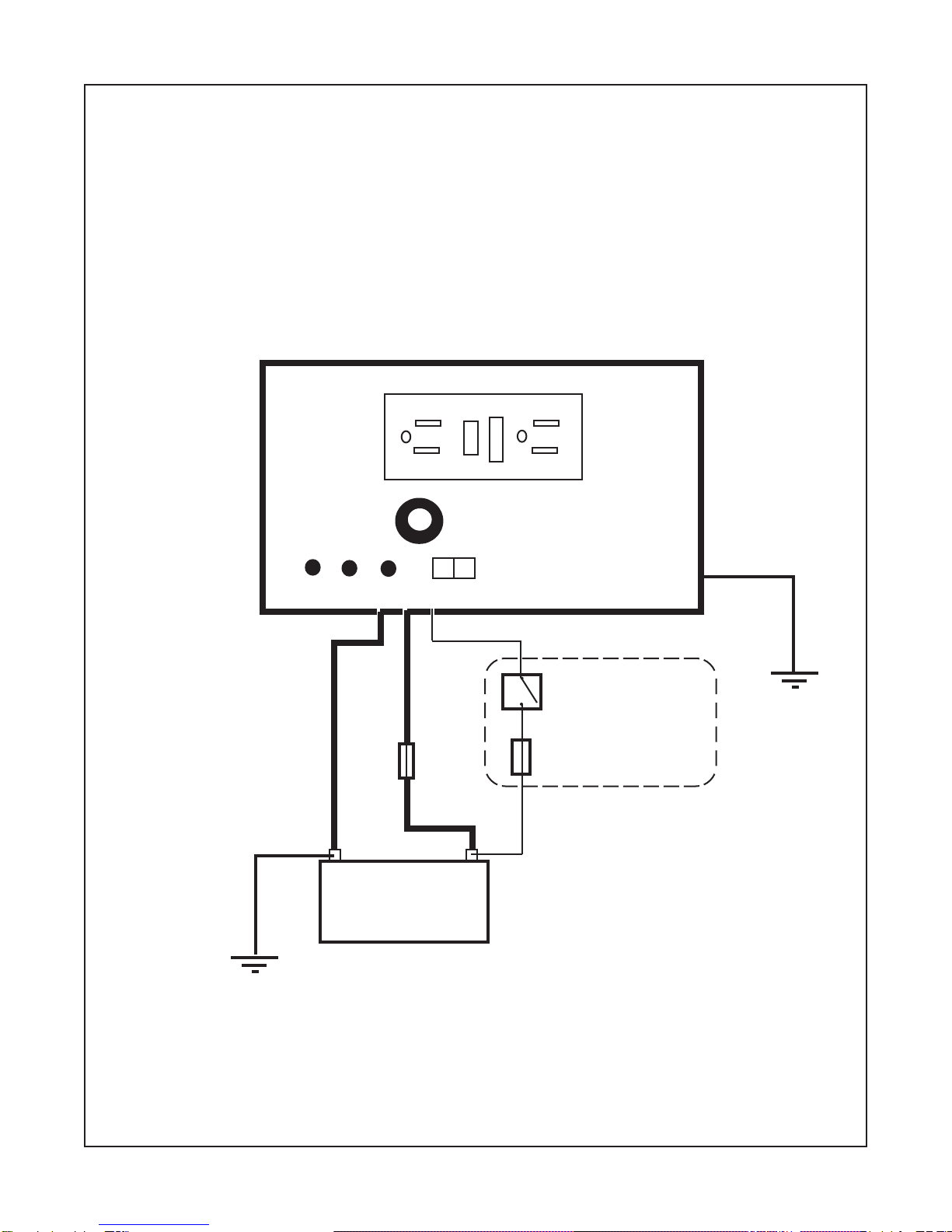
3.05.3 U.L. codes require the use of an
auxiliaryfuseto beinstalledwithin 18inchesfrom
the battery.
3.05.4 NOTE: Using smaller input cable
or longer length will greatly degrade the inverter
peak performance.
NOTE FOR VEHICLE INSTALLATION:
Do not
use the vehicle chassis as the negative return in
place of a return cable. Use the same size cable
as the positive connection and run directly to the
battery/alternator.
3.05.5 Install the wires on the battery,
inverter and then fuse holder. Make sure that
tight, clean connections are made. Use care not
totouchthe positiveand negative wirestogether.
This will result in a violent spark and could result
in exploding batteries and fire.
3.05.6
CAUTION:
Connecting the inverter
incorrectly to the battery with the polarity re-
versed will cause damage that is not covered
under warranty!
3.05.7 Connect the White wire to the
negative(-)postonthebattery. ConnecttheRed
wire to the fuse that is connected to the positive
(+) post on the battery. A mounting spark may
result when connecting the battery wire.
3.06 Remote ON/OFF Switch - Fig. 1
3.06.1 If a remote switch is not used, no
connection is necessary to the violet wire.
NOTE:
Connectingtheviolet wiretochassis
ground will cause damage not covered un-
der warranty!
3.06.2 All material used for the remote
switch should be UL listed and installed per code.
3.06.3 The remote switch should be single
pole, single throw with a 5 Amp rating. The wire
used should be at least 18 gauge.
3.06.4 The switch should be mounted at
a convenient location with approved strain relief.
3.06.5 The remote switch should be con-
nected to the violet wire extending from the unit,
Page 3
externalACpowersourceisappliedtotheinverter’s
AC outlet or its hardwire output.
CAUTION:
Besuretheinverter'scircuitbreakeror
fuse are turned “OFF” during installation.
NOTE: AllwiringmustfollowtheNationalElectric
Code, Provincial or other codes in effect at the
time of installation, regardless of suggestions in
this manual. All wires should be copper conduc-
tors.
3.03 Mounting
3.03.1 Locate a suitable, secure flat mount-
ing surface as close to the battery as possible
without being in the same airtight compartment.
The maximum recommended distance between
the mounting location and the battery is 20 feet.
3.03.2 The location should have adequate
ventilation and clearance to maintain room tem-
perature while the unit is operating. At least 1/2
inch of clearance is required on all sides.
3.03.3 Secure the unit with #8 or larger
screws or bolts in the mounting slots on the
flanges of the chassis.
3.04 Chassis Bonding Lug - FIG. 1
3.04.1 Connect a #8 gauge or greater cop-
per wire between the bonding lug on the inverter
and the earth grounding system or the vehicle
chassis.
3.05 Battery Wiring - FIG. 1
3.05.1
CAUTION:
Make sure that hydrogen
gas does not accumulate near the battery by
keeping the area well ventilated. A spark may
result when connecting the battery wiring due to
an initial charging of the internal input capacitor.
3.05.2 The recommended stranded copper
wirebetween the batteryand the inverterand the
necessary line fuse are indicated:
Battery to Inverter Distance (feet)
up to 10 11 to 15 16 to 20
Cable 8 awg 6 awg 6 awg
Fuse 100 Amps 150 Amps 150 Amps

using the furnished connector. Connect the wire
totheloadsideoftheswitch. Connectthelineside
of the remote switch to fused, positive battery.
Theactualloaddrawthrough the remoteswitchis
less than .1 amp. The fuse should not be larger
thanthe amp capacityof theswitch orthe hookup
wire. A recommended fuse is a Bussman SFE-4
or Littlefuse 311-004.
3.07 120 VAC Output
3.07.1 The 120 VAC output of the inverter
is provided by the GFCI receptacle output on the
front of the inverter.
4. START UP / OPERATION
4.01 To operate the inverter turn the switch to
“ON”. Make sure that the output breaker and
Ground Fault Circuit Interrupter are reset.
4.02 Turn the switch to “Off” when not in use.
5. TROUBLESHOOTING
5.01 Dimensions offers free phone consulta-
tionconcerninginstallationortroubleshooting. Call
the Customer Service Department at 800-553-
6418 or (651) 653-7000, fax: 651-653-7600; e-
mail: [email protected]
5.02 If the inverter fails to operate, use the
followingtroubleshootingprocedure.
5.02.1 Connect a 100 watt light bulb to the
inverter output.
5.02.2 Make sure the inverter is turned on,
theoutput circuitbreaker isreset and that the line
fuse is good.
5.02.3 Observe thefault indicating light on the
front of the inverter. If the low battery light is lit,
turn inverter “Off” for 5 seconds, then turn “On”
again. Ifthelowbatterylightturnsonagain,check
battery wiring, battery state-of-charge and volt-
age.
5.02.4 If the inverter feels hot, it may have
shut down by over temperature. The inverter
must be left to cool to 40 degrees C (104 degrees
F). Checktoseethattheinverterisnotinaclosed
compartment.
5.02.5 If the above steps are com-
pletedand
theinverterstillwillnotoperatesatisfac-
torily callSensata for a return authorization num-
ber.
Page 4

Page 5
DIMENSIONS INVERTER
NOTE: The Inverter must be connected to the 12 volt battery with the correct polarity.
The red wire is "POSITIVE +", and the white wire is "NEGATIVE -".
Connecting the inverter improperly will cause damage that is not covered
under warranty.
Battery
12 volts
-+
Figure #1 INSTALLATION DIAGRAM
White (-) Red (+)
Fuse
Customer supplied
Remote On/Off switch
Fuse
Violet
Bonding Lug

Page 6
Limited Warranty Terms & Conditions
SHIPPING TERMS: F.O.B. St. Paul Minnesota. Freight prepaid and billed, subject to prior credit approval.
MINIMUM ORDER: $50.00 Net Price
LOSS OR DAMAGE: Loss or damage in transit are the responsibility of the carrier. Any claim should be filed with the delivering transport
company. Invoice, Bill of Lading and Delivery receipt with damage noted therein must accompany any claims for freight damage. Claims for
shortage and lost shipments must be made in writing to Sensata Technologies, Power Controls White Bear, St. Paul, MN within 10 days of
date of shipment. Claims not reported within this time frame will not be honored.
PRICES: Prices are subject to change without notice. All orders are subject to acceptance at the factory. We reserve the right to invoice
prices in effect at time of shipment.
TERMS: Net 30 days with approved credit, credit card or C.O.D.
RETURNGOODSPOLICY:
•No returned materials will be accepted without an accompanying Returned Materials Authorization Number (RMA) from the factory.
The RMA number must be clearly printed outside the inverter box.
•Credit will be issued for returned goods to the original purchaser within 60 days of purchase, provided the inverter is returned to
Sensata unused and not mounted. The amount of credit will be issued at Sensata's discretion based on the condition of the product.
•Customer must be in good standing with Sensata Technologies.
•Inverters that are discontinued, high-voltage (over 24vdc), special-order or used are excluded and will not be eligible for credit. Non-
inverter items such as cable assemblies, fuses and fuse holders, will not be eligible for credit.
•Support components supplied by Sensata vendors will be covered under that manufacturer's credit return policy.
•Customer pays return freight.
PLEASE SHIP AUTHORIZED RETURNS TO:
Sensata Technologies / 4467 White Bear Parkway / St. Paul, MN 55110
Return Freight Prepaid
LIMITED WARRANTY:
Sensata Technologies extends the following warranty to the original purchaser of those goods subject to the qualifications indicated.
Sensata warrants to the original purchaser for use that the goods or any component thereof manufactured by Sensata will be free from
defects in workmanship from the date of purchase for the period listed on the product label, provided such goods are installed, maintained
and used in accordance with Sensata and the original manufacturer's written instructions. Damages caused by the misuse, undue care or
obvious wear through use will not be covered by this warranty.
Components not manufactured by Sensata, but used within the assembly provided by Sensata, are subject to the warranty period as
specified by the individual manufacturer of said component, provided such goods are installed, maintained and used in accordance with
Sensata and the manufacturer's written instructions.
Sensata's sole liability and the Purchaser's sole remedy for a failure of goods under this limited warranty and for any and all claims arising
out of the purchase and use of the goods, shall be limited to the repair or replacement of the goods that do not conform to this warranty.
To obtain repair or replacement service under the limited warranty, the purchaser must contact the factory for a Return Material Authori-
zation (RMA). Once obtained, send the Return Material Authorization Number along with the defective part or goods to: Sensata
Technologies, Power Controls White Bear, 4467 White Bear Parkway, St. Paul, MN 55110, Return Freight Prepaid.
THERE ARE NO EXPRESS WARRANTIES COVERING THESE GOODS OTHER THAN AS SET FORTH ABOVE. THE IMPLIED WARRANTIES OF
MERCHANTABILITY AND FITNESS FOR A PARTICULAR PURPOSE ARE LIMITED IN DURATION TO ONE YEAR FROM DATE OF PURCHASE.
SENSATA TECHNOLOGIES ASSUMES NO LIABILITY IN CONNECTION WITH THE INSTALLATION OR USE OF THE PRODUCT, EXCEPT AS
STATED IN THIS LIMITED WARRANTY. SENSATA TECHNOLOGIES WILL IN NO EVENT BE LIABLE FOR INCIDENTAL OR CONSEQUENTIAL
DAMAGES.
WARNING:
LIMITAIONS ON USE: DIMENSIONS brand products are not intended for use in connection with Life Support Systems and
for Avionic use. Sensata Technologies makes no warranty or representation in connection with their products for such uses.
R
Table of contents
Other m-Dimension Inverter manuals
Popular Inverter manuals by other brands

Scheppach
Scheppach SG2600 Translation from the original instruction manual

Toshiba
Toshiba TOSVERT IPE001Z instruction manual

Aerpro
Aerpro FTS420 User instruction manual

SOLARIMMERSION
SOLARIMMERSION Mark IV Advanced Installation Manual

Solectria Renewables
Solectria Renewables PVI 2500 Installation and operation manual

Frico
Frico Soloclim SC17 Original instructions