m-Dimension ADI-64/1000 User manual

ISO 9001:2008 Certified Company
DC to AC Power Inverters
OWNERS MANUAL for Models:
ADI-64/1000
ADI-64/2100
ADI-64/3600
Including Options D, F & T
Form 121077
121077C
OWNERS MANUAL JANUARY 2007
Manufacturer of DimensionsTM Inverters
4467 White Bear Parkway
St. Paul, MN 55110
Phone: 651-653-7000 Fax: 651-653-7600
E-mail: [email protected]
Web: www.dimensions.sensata.com

OWNERS MANUAL
FOR SENSATA TECHNOLOGIES
DIMENSIONS INVERTERS
Model ADI-64/1000
Model ADI-64/2100
Model ADI-64/3600
Including Option D, F & T
Table of Contents
Page
1. General . . . . . . . . . . . . . . 2
2. Description . . . . . . . . . . . 2
3. Installation . . . . . . . . . . . 2
4. Start Up/Operation. . . . . . 4
5. Troubleshooting. . . . . . . . 4
6. Installation Figure 1 . . . . . 5
7. Limited Warranty . . . . . . . 6
1. GENERAL
1.01 Dimensions inverters have been de-
signedandmanufacturedformanyuserapplica-
tions and long life. They utilize patented con-
struction methods and high technology elec-
tronic parts and circuitry.
1.02
CAUTION:
Invertersproducehazardous
voltages, to avoid risk of harm or fire the unit
must be properly installed. There are no user
serviceable parts inside, do not remove the
cover.
CAUTION:
The inverter should not be mounted
in a location that may be exposed to rain or spray.
CAUTION:
The inverter should not be installed
in a zero clearance enclosure.
CAUTION:
Damage to the inverter will occur if
correct polarity is not observed when installing
the DC input cables.
CAUTION:
Damage to the inverter will occur if
an external AC power source is applied to the
inverter’s AC output or it’s hardwire output.
CAUTION:
Theinvertercontainsacircuitbreaker
and capacitor that may produce a spark. Do not
mount in a confined battery or gas compart-
ment.
CAUTION:
Working in the vicinity of lead-acid
batteriesisdangerous.Batteriesgenerateexplo-
sive gases during operation. There is a risk of
acidexposure.Thereisalsoariskofhigh current
discharge from shorting the battery that can
cause fire and explosion.
CAUTION:
Be sure both the inverter and, if
used, the external AC input circuit breaker or
fuse are turned "OFF" during installation.
2. DESCRIPTION
2.01 The inverter converts 64 VDC to 120
VAC, 60 HZ, having a quasi-sine wave form.
2.02 Units with the "F" option have 220
VAC, 50 Hz output. Units with the "D" option
have 120/240 VAC, 60 Hz output.
2.03 The inverter has internal protection
against output short circuit, output overload and
high temperature conditions. Also, there is a
thermally controlled cooling fan.
2.04 The inverter is designed to operate
almost any 120VAC (120/240VAC with "D" op-
tion), 60 HZ, single phase equipment within its
powerratings,unlesstheequipmentisspecifically
designed for a pure sine waveform.
3. INSTALLATION
3.01 The following instructions should be
toroughly read and understood before installa-
tion.
3.02
CAUTION:
Inverters produce hazard-
ousvoltages, toavoidrisk ofharm or firethe unit
must be properly installed.
CAUTION:
Damage to the inverter will occur if
correct polarity is not observed when installing
the DC input cables.
CAUTION:
Damage to the inverter will occur if
an external AC power source is applied to the
inverter’s AC outlet or it’s hardwire output.
CAUTION:
Be sure both the inverter and the
Page 2

Page 3
external AC input circuit breaker or fuse are
turned “Off”during installation.
NOTE: All wiring must follow the National
Electric Code, Provincial or other codes in effect
at the time of installation, regardless of sugges-
tions in this manual. All wires should be copper
conductors.
3.03 Mounting
3.03.1 Locate a suitable, secure vertical or
horizontal mounting surface as close to the
battery as possible without being in the same air
tightcompartment. Themaximumrecommended
distance between the mounting location and the
battery or power source is 40 feet.
3.03.2 The location should provide ad-
equate ventilation and clearance to maintain
room temperature while the unit is operating. At
least1/2inchofclearanceisrequiredonallsides.
3.03.3 Secure the unit with 1/4 inch screws
or bolts in the mounting slots on the flanges of
the chassis.
3.04 Chassis Bonding Lug - FIG. 1
3.04.1 Connect a #8 gauge or greater
copper wire between the bonding lug on the
inverter and the earth grounding system or the
vehicle chassis.
3.05 Battery Wiring - FIG. 1
3.05.1
CAUTION:
Assure that hydrogen
gas does not accumulate near the battery by
keeping the area well ventilated. A spark may
result when connecting the final battery wiring
due to an initial charging of the internal input
capacitor.
3.05.2 Use stranded copper wire between
the battery and inverter as indicated. A line fuse
must be installed between the battery or power
supply and the inverter, within 18 inches of the
power source.
DC Input Wire Lengths (maximum)
and Fusing Guide
Distance (feet)
Model 1-19 20-40 Fuse
64/1000 10 ga 8 ga 100A
64/2100 6 ga 4 ga 200A
64/3600 4 ga 2 ga 250A
3.05.3 NOTE: Using smaller input cable
orlongerlengthwillgreatlydegradetheinverter's
peak performance.
3.05.4 Install the wires at the power
source,inverterandthenfuseholder. Makesure
thatgood,cleanconnectionsaremade. Usecare
not to touch the positive and negative wires
together. This will result in a violent spark and
could result in exploding batteries and fire.
3.05.5
CAUTION:
Connecting the
inverter to the power source with reverse polar-
ity will cause damage that is not covered under
warranty.
3.05.6 The D.C. input terminals are lo-
cated in the wiring compartment. A mounting
spark may result when connecting the battery
wire,due to an initialcharge of the internalinput
capacitor.
3.06 120 VAC Output
3.06.1
CAUTION:
Do not connect an
other source of AC power directly to the output
of the inverter. This will result in damage to the
inverter that is not covered under warranty!
3.06.2 120 VAC output of the inverter is
providedat thereceptacle outleton theinverter.
3.06.3 The 120 VAC output is also
presentedbehind the wiringcompartmentpanel
fordirecthardwire connection. The black wire is
hot, the white wire is neutral and the green wire
isground.Thecableclampstrainreliefshouldbe
used to secure the field wires.
3.06.4 The remote AC outlets should be
mounted at a convenient location in a listed

5. TROUBLESHOOTING
5.01 Sensata offers free phone consultation
concerninginstallationortroubleshooting. Callthe
Customer Service Department at: 1-800-553-
6418 or 651-653-7000; fax: 651-653-7600 e-
mail: [email protected]
NOTE: Since the inverter has a quasi-sine
waveform,aTRUE RMSvoltmeter isrequiredfor
an accurate reading. Other volt meters that use
averagingcircuitry will give incorroect readings.
5.02 If the inverter fails to operate, use the
following troubleshooting procedure.
5.02.1 Connect a 100 watt light bulb to
the inverter output.
5.02.2 Make sure that the inverter is
turned “On”, and the circuit breakers are reset.
5.02.3 Observe the fault indicating lights
on the front of the inverter.
a) The Low input voltage light indicates a
low D.C. condition. Switch the inverter “Off” for
5seconds,then “On” again. The light coming on
again indicates a fault in the D.C. wiring,power
source capacity and voltage or the line fuse.
b) The Overload light indicates an output
wiring short circuit or a load that is too large for
the power rating of the inverter. Switch the
inverter “Off”, remove the short circuit or exces-
sive load from the output, then switch the in-
verter back “On”.
c) The High temperature light indicates
the inverter has overheated. The unit will auto-
matically turn back on when it has cooled to 40
degrees C. Verify that the inverter is not in a
closed compartment and that the fan is not
blocked.
5.04 Call Sensata for technical assistance
and/orareturnauthorizationnumberiftheabove
steps are completed and the inverter still will not
operate satisfactorily.
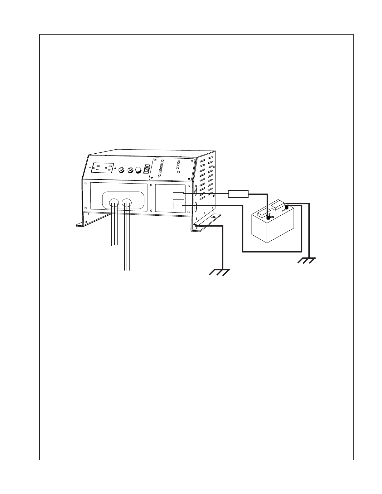
outlet box with approved strain relief.
3.07 120/240 VAC Dual Output
(D option)
3.07.1 The output is presented behind the
wiring compartment panel for direct hardwire
wireleads. Thetwoblackwiresarehot,thewhite
wire is neutral and the green wire is ground. The
cable strain relief should be used to secure the
field wires.
3.08 220 VAC, 50 Hz Output
(F option)
3.08.1 The output is presented behind the
wiring compartment panel for direct hardwire
connection. The two black wires are hot, and the
green wire is ground. The cable strain relief
should be used to secure the field wires.
3.09 120 VAC Input (T option)
3.09.1 120 VAC, 60 HZ power from the
electric utility or generator can be connected to
the inverter with hardwire connections at the AC
Input wire leads provided in the hardwire com-
partment. The black wire is hot, the white wire is
neutral, and the green wire is ground. The cable
clamp strain relief should be used to secure the
field wires.
3.09.2 The input circuit should have 30
amp circuit protection from the distribution.
3.09.3 If provided with the "T" option,
when external 120 VAC is supplied, the internal
transfer switch is automatically activated, the
inverter is turned "Off", and the inverter's loads
will operate from external AC.
4. START UP/OPERATION
4.01 To operate the inverter, turn the switch
to “ON”. Assure that the breakers are reset.
Page 4

NEG
A.C. A.C. Input REMOTE
Output Transfer POS
A.C
OUTPUT
WARNING: CONNECTING THE BATTERY OR POWER SUPPLY WITH THE
WRONG POLARITY TO THE INVERTER WILL CAUSE DAMAGE THAT IS NOT
COVERED UNDER THE WARRANTY.
FIG. 1 INSTALLATION WIRING
Page 5
FUSE
A.C. INPUT EARTH OR CHASSIS
("T" OPTION) EARTH OR CHASSIS GROUND
GROUND
64VDC

Page 6
Limited Warranty Terms & Conditions
SHIPPING TERMS: F.O.B. St. Paul Minnesota. Freight prepaid and billed, subject to prior credit approval.
MINIMUM ORDER: $50.00 Net Price
LOSS OR DAMAGE: Loss or damage in transit are the responsibility of the carrier. Any claim should be filed with the delivering transport
company. Invoice, Bill of Lading and Delivery receipt with damage noted therein must accompany any claims for freight damage. Claims for
shortage and lost shipments must be made in writing to Sensata Technologies, Power Controls White Bear, St. Paul, MN within 10 days of
date of shipment. Claims not reported within this time frame will not be honored.
PRICES: Prices are subject to change without notice. All orders are subject to acceptance at the factory. We reserve the right to invoice
prices in effect at time of shipment.
TERMS: Net 30 days with approved credit, credit card or C.O.D.
RETURNGOODSPOLICY:
•No returned materials will be accepted without an accompanying Returned Materials Authorization Number (RMA) from the factory.
The RMA number must be clearly printed outside the inverter box.
•Credit will be issued for returned goods to the original purchaser within 60 days of purchase, provided the inverter is returned to
Sensata unused and not mounted. The amount of credit will be issued at Sensata's discretion based on the condition of the product.
•Customer must be in good standing with Sensata Technologies.
•Inverters that are discontinued, high-voltage (over 24vdc), special-order or used are excluded and will not be eligible for credit. Non-
inverter items such as cable assemblies, fuses and fuse holders, will not be eligible for credit.
•Support components supplied by Sensata vendors will be covered under that manufacturer's credit return policy.
•Customer pays return freight.
PLEASE SHIP AUTHORIZED RETURNS TO:
Sensata Technologies / Power Controls White Bear / 4467 White Bear Parkway / St. Paul, MN 55110
Return Freight Prepaid
LIMITED WARRANTY:
Sensata Technologies extends the following warranty to the original purchaser of those goods subject to the qualifications indicated.
Sensata warrants to the original purchaser for use that the goods or any component thereof manufactured by Sensata will be free from
defects in workmanship from the date of purchase for the period listed on the product label, provided such goods are installed, maintained
and used in accordance with Sensata and the original manufacturer's written instructions. Damages caused by the misuse, undue care or
obvious wear through use will not be covered by this warranty.
Components not manufactured by Sensata, but used within the assembly provided by Sensata, are subject to the warranty period as
specified by the individual manufacturer of said component, provided such goods are installed, maintained and used in accordance with
Sensata and the manufacturer's written instructions.
Sensata's sole liability and the Purchaser's sole remedy for a failure of goods under this limited warranty and for any and all claims arising
out of the purchase and use of the goods, shall be limited to the repair or replacement of the goods that do not conform to this warranty.
To obtain repair or replacement service under the limited warranty, the purchaser must contact the factory for a Return Material Authori-
zation (RMA). Once obtained, send the Return Material Authorization Number along with the defective part or goods to: Sensata
Technologies, Power Controls White Bear, 4467 White Bear Parkway, St. Paul, MN 55110, Return Freight Prepaid.
THERE ARE NO EXPRESS WARRANTIES COVERING THESE GOODS OTHER THAN AS SET FORTH ABOVE. THE IMPLIED WARRANTIES OF
MERCHANTABILITY AND FITNESS FOR A PARTICULAR PURPOSE ARE LIMITED IN DURATION TO ONE YEAR FROM DATE OF PURCHASE.
SENSATA TECHNOLOGIES ASSUMES NO LIABILITY IN CONNECTION WITH THE INSTALLATION OR USE OF THE PRODUCT, EXCEPT AS
STATED IN THIS LIMITED WARRANTY. SENSATA TECHNOLOGIES WILL IN NO EVENT BE LIABLE FOR INCIDENTAL OR CONSEQUENTIAL
DAMAGES.
WARNING:
LIMITAIONS ON USE: DIMENSIONS brand products are not intended for use in connection with Life Support Systems and
for Avionic use. Sensata Technologies makes no warranty or representation in connection with their products for such uses.
R
This manual suits for next models
2
Table of contents
Other m-Dimension Inverter manuals