9
LOWER ASSEMBLY ACCESS
Tools Required: Philip’s head screwdriver
Needle nose pliers.
WARNING: If the replace was operating prior to ser-
vicing, allow at least 20 minutes for light bulbs and heating
elements to cool off to avoid accidental burning of skin.
WARNING: Disconnect power before attempting any
maintenance to reduce the risk of electric shock or damage
to persons.
!NOTE: For replacing the Heater Assembly or the
Sump Pump Assembly please skip this section and go to
the corresponding pages for these parts.
For all other parts please proceed with the following instruc-
tions:
Remove the rebox out of the cabinet or wall frame that 1.
surrounds the unit.
Disconnect power before attempting any maintenance.2.
Unplug the replace from the outlet. •
Or turn the breaker off at the electrical panel.•
Remove the 4 screws from the rear-middle panel.3.
(There is an upper, middle and lower panel on the back
of the replace).
Remove the 2 screws on the front lower corners. (1) 4.
on the left and (1) on the right side behind the drawer.
Remove the 2 screws – (1) left and (1) right rear corner 5.
of the LED log set. These screws are inserted directly
into the rubberized material that forms the logs.
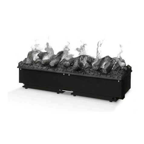
Lift the backside of the lower assembly (logs and draw-6.
er) just enough to clear the hidden mounting brackets
located beneath the logs. Slide this entire lower as-
sembly forward a few inches. Disconnect the 3 wires
from the white power cord connected to the terminal
block on the left side. (See Assembly Part Pictures)
!NOTE:Be sure to take note of the original position of
the wires on the terminal block.
Once these wires are disconnected continue to slide7.
this bottom assembly forward and rest it just in front of
the replace chassis.
!NOTE:With this bottom drawer removed you can now
access all parts with the exception of the heater assembly,
which is located on the top panel of the replace.
Identify the part to be replaced and how they are se-8.
cured.
The left side of the drawer has:
2 transformers - Philips head screws•
3 terminal blocks - Philips head screws•
Power Cord - Philips head screws•
The right side of the drawer has:
Remote control receiver/power board - Plastic•
mounting tabs
Stepper board - Plastic Mounting tabs•
Main on/off switch - integral mounting tabs•
(squeeze to release)
3-stage selector switch - integral mounting tabs•
(squeeze to release)
Flame intensity controller - to remove, pull the •
knob off the potentiometer shaft, then using a pair
of needle nose pliers turn the jam nut counter
clockwise through the opening around the shaft.
LED Log set Wire harness plugged into the Re-•
mote Control Receiver - to remove, unplug from
the remote control receiver and remove 5 screws,
– (1) (x4) on each corner and (1) on the front right
side, approximately 3” inches to the left of the
corner screw.
Inside the drawer has:
Halogen Light Assemblies•
Sump Pump Assembly•
Water Reservoir•
Mist Effect Fan/Air Filter •
!NOTE: For removal of components inside of drawer
please see Operation section of this manual.
Remove the wires from the part to be replaced noting9.
their original location.
Release the mounting hardware securing the part, and10.
remove it from it’s location.
Secure the new part into the same location as the11.
original part.
Reconnect the wires according to their original location/12.
conguration.
Re-assemble in reverse order as above.13.
HEATER ASSEMBLY REPLACEMENT
TOOLS REQUIRED: Philip’s head screwdriver
WARNING: If the replace was operating prior to ser-
vicing, allow at least 20 minutes for light bulbs and heating
elements to cool off to avoid accidental burning of skin.
WARNING: Disconnect power before attempting any
maintenance to reduce the risk of electric shock or damage
to persons.
Remove the rebox out of the cabinet or wall frame that 1.
surrounds the unit.
Disconnect power before attempting any maintenance.2.
Unplug the replace from the outlet. •
Or turn the breaker off at the electrical panel.•
Remove the 7 screws, which secure the top panel to3.
the replace from the exterior. (3) on the left side, (3)
on the right side, (1) on the back side of this top panel.
From underneath the heater assembly, mounting panel, 4.
remove the 4 screws that secure the heater assembly
to the rest of the replace.
Disconnect the wires attached to the heater assembly5.
elements and blower motor noting their original location
and reconnect onto the new heater assembly.
Lift the old assembly out of the top heater housing.6.
Line up the new heater assembly and secure with the 47.
original screws from underneath.
Re-attach the 7 screws to the top panel.8.

