List of Figures
No. Title Page
v
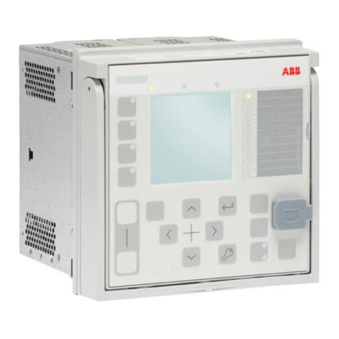
1-1. Faceplate with Main Menu Display ..........................................................................................1-4
1-2. Strategic Loop Controller Components ....................................................................................1-5
1-3. Faceplate Assembly.................................................................................................................1-6
1-4. Module Bus Network with Type CIC01 Computer Interface Command Module.......................1-6
1-5. Module Bus Network with Serial Interface ...............................................................................1-7
1-6. Module Bus Network with Plant Loop ......................................................................................1-7
1-7. Instrument Accuracy and Available Measuring Ranges
for Direct Temperature Inputs (Fahrenheit Scale) ..................................................................1-13
1-8. Instrument Accuracy and Available Measuring Ranges
for Direct Temperature Inputs (Celsius Scale)........................................................................1-14
2-1. External and Mounting Dimensions .........................................................................................2-5
2-2. DC and AC Power Supply Wiring Connections........................................................................2-7
2-3. Power Supply Board ................................................................................................................2-7
2-4. Recommended Single Point Grounding System.................................................................... 2-11
2-5. External Wiring Label .............................................................................................................2-13
2-6. Powered Four to 20 Milliamp Analog Input ............................................................................2-13
2-7. Unpowered or Field Powered Four to 20 Milliamp Analog Input............................................2-14
2-8. Single Ended Voltage Input....................................................................................................2-14
2-9. Differential Voltage Analog Input ............................................................................................2-15
2-10. Thermocouple, Millivolt and RTD Inputs ................................................................................2-15
2-11. Analog Output in Current Mode .............................................................................................2-16
2-12. Analog Output in Voltage Mode..............................................................................................2-16
2-13. Digital Inputs in Nonisolated Mode.........................................................................................2-17
2-14. Digital Inputs in Isolated Mode ...............................................................................................2-17
2-15. Digital Output Circuitry ...........................................................................................................2-18
2-16. Peer-to-Peer Communications Wiring Connections...............................................................2-19
2-17. Termination Board Switch Locations ......................................................................................2-20
2-18. Main Board Jumper Settings ..................................................................................................2-22
2-19. Optional Input Board Jumper Settings ...................................................................................2-23
2-20. Jumper Settings Schematic ...................................................................................................2-25
2-21. Serial Interface Board Jumper Settings .................................................................................2-26
3-1. Setup Menu..............................................................................................................................3-2
3-2. Process Display Selections......................................................................................................3-8
3-3. AI3 and AI4 Calibration Connections .....................................................................................3-14
4-1. Configuration Menu..................................................................................................................4-2
4-2. Test Quality/Trip Block Configuration .....................................................................................4-24
4-3. Analog Output Quality ............................................................................................................4-25
4-4. Reverse Acting Controllers .................................................................................................... 4-27
5-1. Operator Interface Controls......................................................................................................5-2
5-2. Process Display Screen ...........................................................................................................5-4
5-3. Changing Controller Modes .....................................................................................................5-8
5-4. Trend Screen Description.......................................................................................................5-18
5-5. Entering the Execute Mode....................................................................................................5-22
6-1. Troubleshooting Flowchart .......................................................................................................6-2
6-2. Checking Common Mode Voltage............................................................................................6-6
8-1. Location of ROMs on Operator Interface Board.......................................................................8-3
8-2. Removing the Main Board........................................................................................................8-4
8-3. Replacing Power Supply Board Fuses.....................................................................................8-4
8-4. Parts Drawing...........................................................................................................................8-8
A-1. Single Loop Control, Internal Set Point ................................................................................... A-1
A-2. Single Loop Control, Internal Set Point, with Temperature Input ............................................ A-2
A-3. Single Loop Control, External Set Point.................................................................................. A-3
A-4. Single Loop Control, External Set Point, with Two Temperature Inputs.................................. A-4
