DITTING KR 804 User manual

Page 1
Operating instructions
KR / KF 804
KR 804 KF 804
TYPE
Voltage
Manuf. no.

Page 1
4 Faults / action 8
4.1 Action in event of a fault 8
4.1.1 Table with possible malfunctions 9
4.2 Repairs 9
4.2.1 Unblocking the discharge tube 9
4.2.2 Unblocking the grinding unit 9
4.2.3 Replacing the rubber bolt (KF only) 10
4.2.4 Circuit breaker 10
5 Customer service 11
6 CE Declaration of conformity 11
Table of content
1 General 2
1.1 Warranty information 2
1.2 Transfer declaration 2
1.3 General safety instructions 3
1.3.1 Information and safety symbols 3
2 Installation of coee grinder 4
2.1 Description and installation of unit 4
2.2 How to use the coee grinder 5
3 Care / maintenance / adjustment 6
3.1 Care and cleaning of the coee grinder 6
3.2 Maintenance 6
3.3 Setting the scale (adjustment) 6
3.3.1 Basic setting (calibration) 7
3.3.2 Changing the scale setting (adjustment for customer
settings) 7
3.4 Replacing the grinding discs 8
Page 2
1 General
Dear Customer,
We congratulate and thank you for purchasing a DITTING quality product.
These operating instructions have been prepared to simplify your use of the
coee grinder.They contain information, advice and instructions for the best
use of your unit.
1.1 Warranty information
ALTHOUGH YOUR COFFEE GRINDER IS DISTINGUISHED BY A HIGH QUAL-
ITY AND SAFETY STANDARD, DAMAGE TO MATERIAL OR RISK OF INJURY
CANNOT BE EXCLUDED IF OPERATED INCORRECTLY, USED IMPROPERLY OR
MISUSED.
THE OPERATING INSTRUCTIONS WILL THEREFORE FAMILIARISE YOU WITH
CORRECT USE OF THE COFFEE GRINDER AND ASSISTYOU TO AVOIDWRONG
OPERATIONS. IF THE ENCLOSED INSTRUCTIONS ARE FOLLOWED EXACTLY,
YOU WILL AVOID DANGERS, REDUCE REPAIR AND STOPPAGE TIMES AND
INCREASE THE RELIABILITY AND SERVICE LIFE OF YOUR UNIT. TO ENSURE
THAT YOU AND YOUR EMPLOYEES TAKE NOTICE OF THE CONTENTS OF THE
OPERATING INSTRUCTIONS AND FOR YOUR OWN SAFETY, WE WOULD ASK
YOU TO COMPLETE THE TRANSFER DECLARATION PRINTED ON THE FOL-
LOWING PAGE, DETACH THIS ALONG THE PERFORATION AND RETURN IT TO
YOUR DEALER.
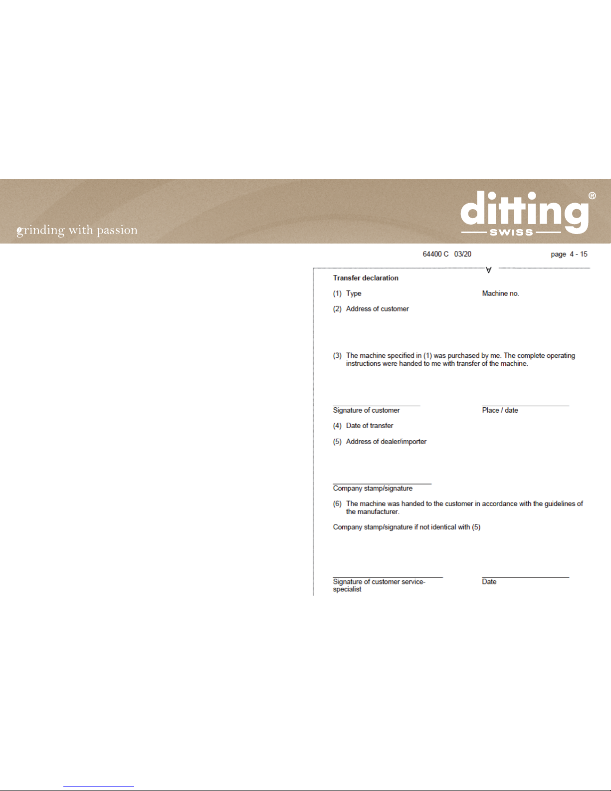
1.2 Transfer declaration
To ensure transfer of the operating instructions to nal consumers.
Note: The following declaration should be completed by the dealer and the
purchaser. The purchaser undertakes to return this declaration to the dealer.
The purchaser thereby certies that the dealer has drawn his attention to the
contentsofoperatinginstructionsno.64400,inparticulartotherelevantsafety
instructions for use of the machine.
Page 3
1.3 General safety instructions
Theoperatinginstructionsmustbekeptpermanentlyattheplaceofoperation
of the machine and if possible attached at the point of installation in the im-
mediate vicinity of the machine.
The competent sales and service personnel must have read the operating in-
structionsbeforeputtingthecoeegrinderintooperationandbefamiliarwith
all functions including action in the event of a fault.
Ifcustomersthemselvesoperatethemachine,anoticemustbe placedclearly
visibleintheimmediatevicinity ofthemachinethatcustomersmustimmedi-
ately call the service personnel responsible in the event of a fault and not try
to eliminate the fault themselves by tampering with the machine.
The machine must be placed in the sales areas so that the sales personnel
responsible can be reached by the customer without diculty.
Onlyoriginalspare-partsmustbeusedforrepairstothegrinder.Ifspare-parts
from other manufacturers are used, the serviceability of the grinder may be
impaired.In addition,furtherinjurytopersons ormaterial damagecannot be
excluded.
The grinder should be installed out of reach of children. Children and users
mustonnoaccountreachintotheopeningsorcomeintocontactwithelectri-
cal components.
Only original grinding discs sharpened by DITTING must be used.
Never reach into the hopper opening while the machine is running.
Nevertouchelectricalcomponentswithconductingobjects,suchasneedles,
pins, cutlery, etc. !
The emission value referred to the workplace is 76 dB(A).
The machine must be electrically protected by fuses according to the name-
plate and the local regulations.
1.3.1 Information and safety symbols
Two information symbols are used in these operating instructions to empha-
sise important comments in the dokument.
Information
Thissymbolindicatesinformationcontainingimportantdata
concerning ecient use. Non-observance can lead to faults.
Safety
This symbol indicates information which if not observed can
leadtodangertopersonsand/orsubstantialmaterialdamage.
The safety instructions must be followed without fail.
Page 4
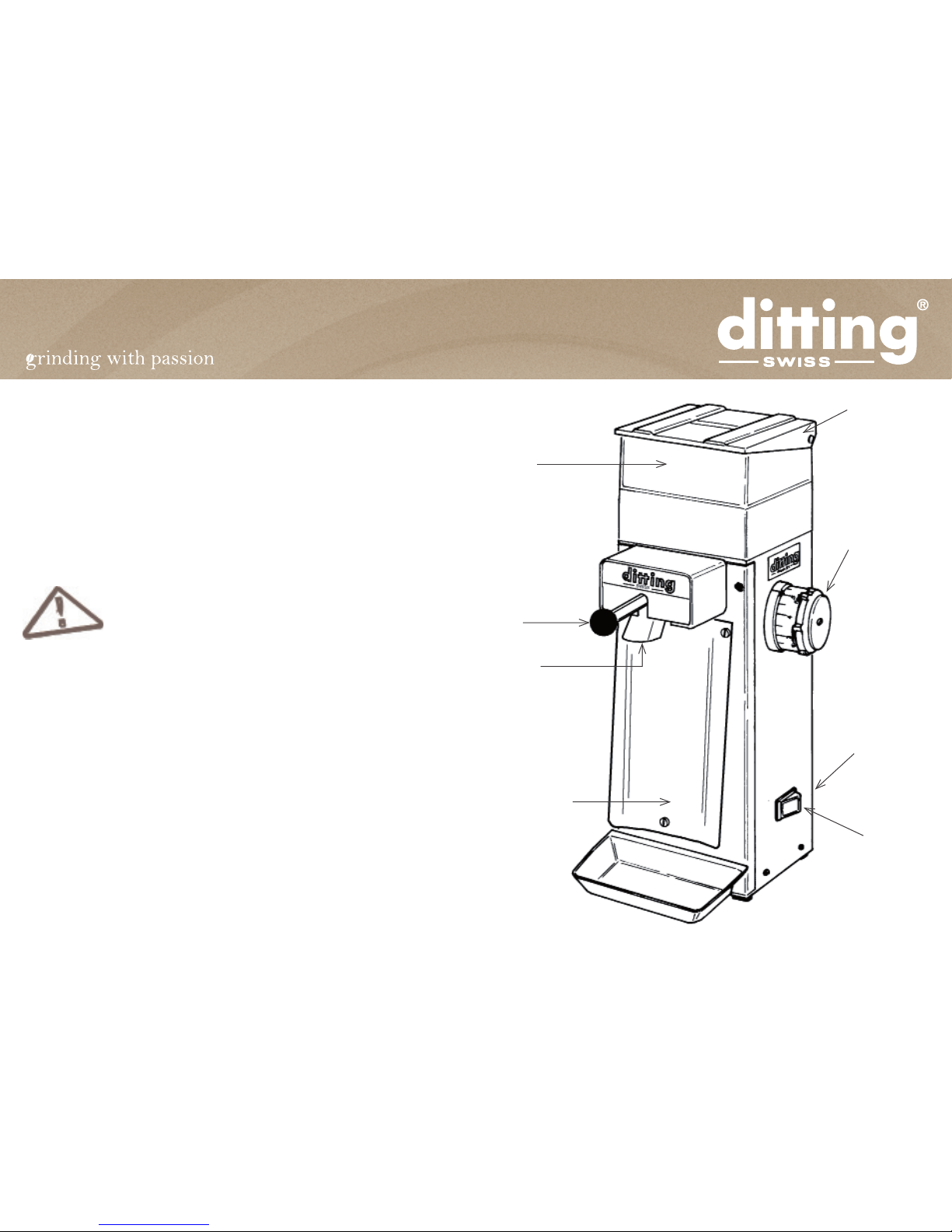
2 Installation of coee grinder
2.1 Description and installation of unit
The KF/R 804 coee grinders are suitable for grinding various kinds of coee.
The grinding neness can be set from «Turkish ne» to «coarse» with an
adjusting knob provided with a scale. The KF/R 804 coee grinders are
suitable for use in small food stores, cafés, restaurants and hotels.The simple
method of operation enables customers to use the grinder themselves in
self-service stores. Operation of the machine can dier slightly from the
descriptionintheseoperatinginstructionsdependingontheversionKForKR.
The grinder must only be installed in dry areas!
Place the coee grinder on a rm, level and non-slip base.
Danger of tipping and slipping on unstable surfaces. Before
connectingthecoeegrindertothe mainssupply,ensurethat
this supply corresponds with the data on the unit nameplate.
Hopper
Bag holding
lever
Bag vibrating
plate (KR only)
Discharge
tube
ON/OFF
switch
Name plate
(backside)
Adjustingknob
Filling cover

Page 5
• Switch on motor with the ON/OFF
switch (6).
• After the end of grinding switch o
the motor (6).
6
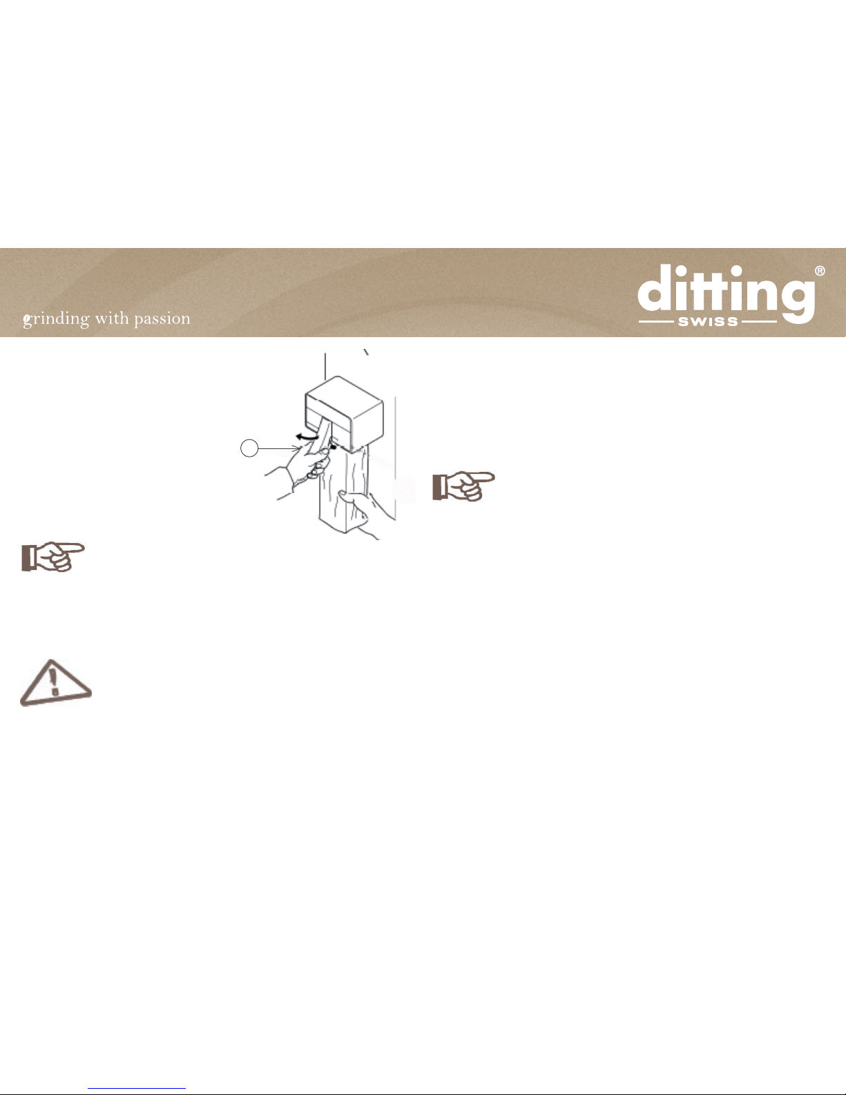
2.2 How to use the coee grinder
• Set the required grinding neness on
the scale with adjusting knob (1).
• Open the lling cover (2) and place
coee beans in hopper (3).
• Clamp empty paper bag over dis-
chargetube(5)withbagholdinglever
(4) and release bag.
Please ensure that the bag is opened fully before clamping
with bag holding lever (4) for grinding.
Reason: If the bag is not fully open, the ground coee cannot
runoutproperly,whichcanresultinabuild-upandmalfunction
of the unit.
1
2
3
4
5
Page 6
3.2 Maintenance
Ifthe grindingqualityisnolongerof therequiredstandard,thegrindingdiscs
must be replaced.
The grinding discs should be inspected for wear after not longer than 12
months.
Periodic checking of the grinding quality and grinding discs
mustonlybeperformedbycompetentspecialistsand/orserv-
ice personnel
3.3 Setting the scale (adjustment)
Settingofthescale(withtheadjustingknob)makesthenenessoftheground
coee correspond with the neness set on the scale (marked).
Setting of the scale must only be performed by persons familiar with the unit
after carefully reading the following instructions.
The basic setting according to 3.3.1 should be made:
• following change of grinding discs
• following inadvertent displacement of the scale setting
Change of scale setting as 3.3.2 should be performed:
• If the desired grinding neness does not correspond with the scale (ad-
justing knob)
• If an individual setting of the grinding neness is desired (customer set-
ting)
• Hold the bag tightly in the hand and
tap the discharge tube clean by pull-
ing and releasing the bag holding le-
ver (4), then remove the bag.
Only grind whole coee beans!
Coee already ground must not be ground again!
3 Care / maintenance / adjustment
3.1 Care and cleaning of the coee grinder
The coee grinder must only be cleaned with a dry cloth.
Do not use an alkaline cleaning agent.
Do not spray coee grinder with water and/or steam.
Reason: It can result in a short-circuit and therefore damage to the unit. The
use of alkalis can aect the avour of the coee.
Thecoeegrindershould becleanedat leastonceweekly andalwaysifsoiled
4

Page 7
3.3.2 Changing the scale setting (adjustment for customer settings)
• Switch o motor.
• Unscrew screw (1) at centre of ad-
justing knob (2) approx. 3 - 5 mm, do
not remove.
• Set required number of divisions by
pullingoutadjustingknob(2),turning
in the corresponding direction and
re-engaging.(1divisioncorresponds
to approx. 3 - 4 mm on the scale.)
• adjustment clockwise = coarser
grinding
• adjustment anti-clockwise = ner
grinding
• Switch on motor.
• Retighten screw at centre of adjust-
ing knob (2).
• Switch o motor.
There must be no sound of grinding discs rubbing together at
scale position 1 = excessive wear of grinding discs.
Checking the setting:
Whenturningtheadjustingknobfromscaleposition1-9there
mustonnoaccountbeasoundofmetalpartsrubbingtogether.
3.3.1 Basic setting (calibration)
If the basic setting is incorrect, friction can occur between the
grinding discs, resulting in excessive wear.
Switch on motor.
• Unscrew screw (1) at centre of ad-
justing knob (2) approx. 3 - 5 mm, do
not remove.
• Pullout(3)adjustingknob(2)andturn
1/4ofarevolutionanti-clockwise(4).
Release and engage (5) adjusting
knob (2). (1 division corresponds to
approx. 3 - 4 mm on the scale.) Turn
adjusting knob (2) slowly clockwise
to scale position 1 until there is a
sound of grinding discs rubbing to-
gether (6).
• When the sound of grinding discs
rubbing together is heard, turn back
while locked 10 mm anti-clockwise
(7).Pullout(8)adjustingknob(2)and
turn clockwise to scale position 1 (9).
Release adjusting knob (2) and en-
gage (10).
• Retighten screw at centre of adjust-
ing knob (2).
• Switch o motor.
6
3
4
5
2
6
3
4
5
2
2
1
2
2
2
1

Page 8
All supporting (mating) surfaces of stationary disc ange, ro-
tating disc ange, grinding discs and grinding case must be
absolutely clean before assembly.
Only in this way can perfect grinding be guaranteed
• Plug in power cable, switch on cof-
fee grinder briey. If it blocks or
there is a sound of metal parts rub-
bingtogether,thescalesetting must
be adjusted according to 3.3.2.
• Retighten screws (6) of the station-
ary disc ange. For this purpose the
hopper (4) must be removed again
and then re-tted.
• Perform basic setting (calibration)
according to 3.3.1.
Retighten hopper lock (3) after reassembly (see illustration
page 11).
4 Faults / action
4.1 Action in event of a fault
Whenoperated bycustomers,it mustbe ensuredthat person-
nelarenotiedintheeventofafaultandthatcustomersdonot
try torepairthe machinethemselves.Thegrindermustonlybe
opened,inspectedanddismantledbypersonsfamiliarwiththe
methodofoperationofthemachine,whohavepreviouslyread
these operating instructions through carefully.
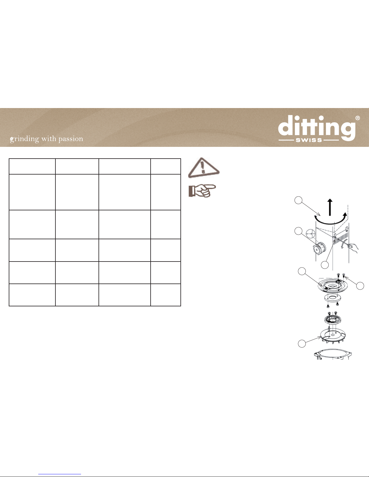
3.4 Replacing the grinding discs
Before changing grinding discs switch o motor without fail
and disconnect power cable !
The grinding discs must only be replaced by persons familiar
with operation of the machine according to the following in-
structions.
• Switch o motor and pull out pow-
er cable. Set adjusting knob (2) to
coarse grinding scale position 9.
• Release left-hand hopper lock (3)
only,butdonotremove.Turnhopper
(4) counter-clockwise through ap-
prox. 15° and remove.
• Remove stationary disc ange (5) by
releasing screws (6) (see illustra-
tion) and dismantle grinding discs.
Dismantle lower grinding disc from
rotating disc ange (rotary ange 7).
• Screw new grinding discs to the
cleaned stationary and rotating disc
anges (5 + 7).
• For resharpened grinding discs the
shims if supplied should be inserted
between grinding disc and ange.
• Then re-assemble parts in reverse
sequence.
5
7
6
4
2
3
6
Page 9
4.2 Repairs
Switch o motor and pull out power cable before all major re-
pairsrequiring workinside the machine,in orderto avoiddan-
gerofinjurywhileworkingonmotorwhilerunningandelectric
shock !
The electrical wiring diagram for this unit can be found inside
the front panel.
4.2.1 Unblocking the discharge tube
• Switch o motor and pull out power ca-
ble.
• Unblock discharge tube from outside as
far as possible.
• Set adjusting knob (1) to coarse grind-
ing scale position 9 and switch motor
on again. This frequently unblocks the
grinder and extracts any foreign bodies
in the grinding unit.
• If the motor still does not run, continue
according to 4.2.2.
4.2.2 Unblocking the grinding unit
• Switch o motor and pull out power
cable.
• Remove coee beans from hopper (4)
(use a vacuum cleaner if necessary).
• Release left-hand hopper lock (3) only,
but do not remove.
• Turn hopper (4) counter-clockwise
through approx. 15° and remove.
• Remove stationary disc ange (5) by
releasing screws (6) (see illustration).
4.1.1 Table with possible malfunctions
Fault Result Action (information
text)
Re.
Grinder cannot be
switched on
ON/OFF switch
does not light
Circuit breaker
Check power ca-
ble, connection and
building fuses
Reset circuit breaker
4.2.4
Grinder jams, mo-
tor does not start
ON/OFF switch
lights
Unblock discharge
tube
Unblock grinding
unit
4.2.1
4.2.2
4.2.4
Irregular grinding Checkgrindingdiscs
for wear and replace
if necessary
3.4
Increasedamount
of dust
Checkgrindingdiscs
for wear and replace
if necessary
3.4
Bag slips or is no
longer held prop-
erly
Replace rubber bolt 4.2.3
4
2
3
5
7
6
Page 10
• Remove foreign bodies. Check grinding discs, rotating and stationary
disc ange, etc. for damage.
•
All supporting surfaces of stationary disc ange, rotating disc
ange, grinding discs and grinding case must be absolutely
clean before assembly.
• Only in this way can perfect grinding be guaranteed.
• Then re-assemble parts in reverse sequence.
• Plug in power cable, switch on coee grinder briey.
If the coee grinder should block or there is a sound of metal
parts rubbing together, the scale setting must be adjusted ac-
cording to 3.3.2.
• Retighten screws (6) of the stationary disc ange. For this purpose the
hopper (4) must be removed again and then re-tted (see illustration
page 13).
Retighten hopper lock (3) after reassembly (see illustration
page 13).
• Perform basic setting (calibration) according to 3.3.1.
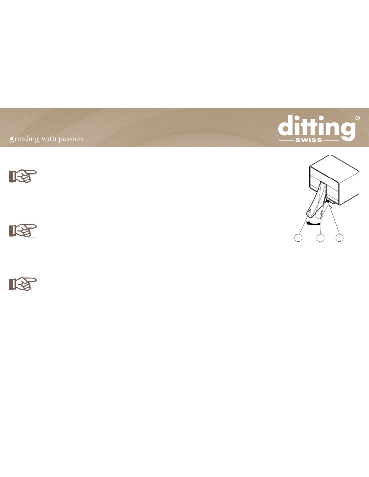
4.2.3 Replacing the rubber bolt (KF only)
• Pull bag holding lever (1).
• Remove sleeve screw (2) with adequate
wrench (no. 17).
• Replace old rubber tube (3) with new
one.
• Re-tighten sleeve screw (2) with ad-
equate wrench and release bag holding
lever.
4.2.4 Circuit breaker
• Set ON/OFF switch to position 0.
• Close overcurrent release by pressing
red button underneath bottom plate.
• The coee grinder is again ready for op-
eration.
123

Page 11
5 Customer service
Ifitisfoundduringmaintenancethatthegrindingdiscsmustberesharpened/
replaced or other repairs must be made, the nearest service centre (see page
1) should be contacted or direct connection made with the factory.
New grinding discs, spare-parts and accessories (also at intermediate times)
can be ordered from our customer service or the relevant agent.
The grinding discs can be resharpened once or twice at the factory.
Data such as manufacturing number and type of power supply as specied
onthenameplateofthecoeegrindershouldbestatedonordersforgrinding
discs, spare-parts and accessories to ensure rapid and ecient advice and
delivery.
6 CE Declaration of conformity

Page 12
Ditting Maschinen AG
Bramenstrasse 11
CH- 8184 Bachenbülach, Switzerland
Tel.: +41 (0)44 864 1800
Fax: +41 (0)44 864 1801
info@dittingswiss.ch - www.dittingswiss.ch
December 2009
Subject to change without prior notice!!
This manual suits for next models
1
Table of contents
Other DITTING Coffee Grinder manuals

DITTING
DITTING KR 805 User manual

DITTING
DITTING KE640 2.0 User guide

DITTING
DITTING KE 640 Vario User manual

DITTING
DITTING KE640 2.0 User guide

DITTING
DITTING KS 3 User manual

DITTING
DITTING ProD User manual

DITTING
DITTING KE640 VARIO User manual

DITTING
DITTING KF 804 User manual

DITTING
DITTING KE 640 Original operating manual

DITTING
DITTING KE640 ES User manual


