manuals.online logo
Brands
  1. Home
  2. •
  3. Brands
  4. •
  5. DMG
  6. •
  7. Elevator
  8. •
  9. DMG GILDA User manual

DMG GILDA User manual

Popular Elevator manuals by other brands

OMS Hypodrive EC 2-25 Lift installation instructions

OMS

OMS Hypodrive EC 2-25 Lift installation instructions

York M36 manual

York

York M36 manual

Cambridge Elevating JOURNEY LU installation manual

Cambridge Elevating

Cambridge Elevating JOURNEY LU installation manual

GSI Group X Series Installation Manual - Original Instructions

GSI Group

GSI Group X Series Installation Manual - Original Instructions

epic power P2S Series installation guide

epic power

epic power P2S Series installation guide

Kongskilde CFG 20 Instruction manual / spare parts list

Kongskilde

Kongskilde CFG 20 Instruction manual / spare parts list

Savaria Orion Planning guide

Savaria

Savaria Orion Planning guide

Savaria Telecab17 owner's manual

Savaria

Savaria Telecab17 owner's manual

Savaria Telecab owner's manual

Savaria

Savaria Telecab owner's manual

Forum SBE-1250 operating instructions

Forum

Forum SBE-1250 operating instructions

WFA GOlfinho SPORTS PANDAPOOL Technical sheet

WFA

WFA GOlfinho SPORTS PANDAPOOL Technical sheet

OLEO LB Series installation guide

OLEO

OLEO LB Series installation guide

Snorkel A46JRT Operator's manual

Snorkel

Snorkel A46JRT Operator's manual

Kone MX10 Maintenance procedures

Kone

Kone MX10 Maintenance procedures

Avanti OCTOPUS XL120 user manual

Avanti

Avanti OCTOPUS XL120 user manual

National Wheel-O-Vator Destiny owner's manual

National Wheel-O-Vator

National Wheel-O-Vator Destiny owner's manual

ZHONGTIAN TDTG36/18 Operation manual

ZHONGTIAN

ZHONGTIAN TDTG36/18 Operation manual

Savaria Vuelift Mini owner's manual

Savaria

Savaria Vuelift Mini owner's manual

manuals.online logo
manuals.online logoBrands
  • About & Mission
  • Contact us
  • Privacy Policy
  • Terms and Conditions

Copyright 2025 Manuals.Online. All Rights Reserved.

93010197_P_gilda-TM_151110_v1.2
V. 1.2
Manuale di Installazione
Installation manual /
Manual de Instalación
Notice technique
Installationshandbuch /
Pulsantiera GILDA con testate metalliche
GILDA faceplate with metal end caps
Consultare il manuale "Precauzioni d'uso e sicurezza"
Refer to the "
Consulter manuel technique "Precautions de securite et d'emploi"
Handbuch lesen "Sicherheits- und Gebrauchsanweisung"
Consulte el manual "Precaucioned de seguridad"
Safety and usage precautions" manual
www.dmg.it
3
1) GILDA - 65/100 mm
1.1) Kit di fissaggio ________________________________________________________ pg. 4
Fixing Kit
1.2) Riferimenti per il fissaggio ______________________________________________ pg. 5
Fixing reference
1.3) Montaggio verticale ___________________________________________________ pg. 6
Vertical fixing
1.4) Montaggio orizzontale _________________________________________________ pg. 9
Horizontal fixing
2) GILDA - 150 mm
2.1) Kit di fissaggio _______________________________________________________ pg. 12
Fixing Kit
2.2) Montaggio verticale ___________________________________________________ pg. 12
Vertical fixing
3) GILDA - 200 mm
3.1) Fissa _______________________________________________________ pg. 15
Fixed
3.2) Apribile ___________________________________________________ pg. 15
Hinge opening
4) GILDA - 200 mm (colonna / column)
Montaggio _______________________________________________________ pg. 17
Fixing
Vite di massa • Screw for earth connection
Vis pour mise à tèrre • Schraub für Erdkabel
Tornillo de tierra
8 mm
INDICE / INDEX
4
Ø 4 x 40 mm
Ø 3,9 x 22 mm
Ø 4 x 16 mm
Ø 6 mm
Testata - End piece
Fungo di Ancoraggio - Fixing hook
Inserto Impronta Torx - Torx fixing tool
A
B
C
D
E
F
G
Vite - Screw
Vite Autofilettante - Self-tapping screw
Vite Torx - Torx screw
Tassello in Nylon - Anchor in Nylon
Oggetto
Item
Rif.
Ref.
Descrizione
Description
1) GILDA 65 / 100 mm
1.1) Kit di fissaggio
Fixing kit
3
3
Q.tà
Q.ty
1
3
1
1
1
Supporto - Support
H
1
Testata completa - End piece complete
I
1
65
100 65/100
5
10 mm
1.2) Riferimenti di fissaggio
Fixing reference
I) Fungo di ancoraggio
GB) Fixing hook
I)
GB) Needed space for LOP releasing (This space must be free).
Ingombro della corsa di sgancio (la zona deve essere lasciata libera)
I)
GB) 24 mm (for 65 mm width plates) - 30 mm (for 100 mm width plates)
24 mm (per piastre larghe 65 mm) - 30 mm (per piastre larghe 100 mm)
I) Prima di iniziare l'installazione, attenersi alle indicazioni sottostanti
GB) Pay attention to the information below before fixing the faceplate.
H I
65
100 65/100
6
1
1.3) Montaggio verticale
Vertical fixing
I)
effettuato il foro.
GB) Mark the fixing hole reference.
Dopo aver preso il riferimento marcare il punto dove verrà
2
I)
Per fissaggio su stipite il diametro del foro cambia in base allo
spessore dello stesso (vedi Tab.1)
Per fissaggio a muro il foro è di diametro 6 mm.
GB) Drill the hole.
For frame fixing the hole diameter depends on the frame
thickness (see Table1).
For wall fixing the hole diameter is 6 mm.
Realizzare il foro.
0,5 ÷ 0,9 mm
0,9 ÷ 1,2 mm
1,2 ÷ 1,5 mm
1,5 ÷ 1,9 mm
Ø foro
Ø hole
Ø 2,95 mm
Ø 3,10 mm
Ø 3,25 mm
Ø 3,50 mm
Tab.1
1,9 ÷ 2,7 mm Ø 3,60 mm
Spessore stipite (metallo)
Frame thickness (metal)
65
100
7
I) Fissare il fungo di ancoraggio (E, pg.4)
Per fissaggio su stipite utilizzare la vite autofilettante (B, pg.4)
Per fissaggio a muro utilizzare la vite (A, pg.4) e il tassello (D, pg.4)
GB) Enter the fixing hook (E, pg.4)
For frame fixing use the self-tapping screw (B, pg.4)
For wall fixing use the screw (A, pg.4) and the anchor (D, pg.4)
3
4
I) Accostare la piastra alla parete facendo combaciare l’asola al fungo di
ancoraggio.
GB) Approach the plate to the wall matching the fixing hole with the fixing
hook.
5
I) Spingere la pulsantiera verso l’alto sino all’arresto.
GB) Push the plate upwards till it doesn't move.
65
100
8
8
6
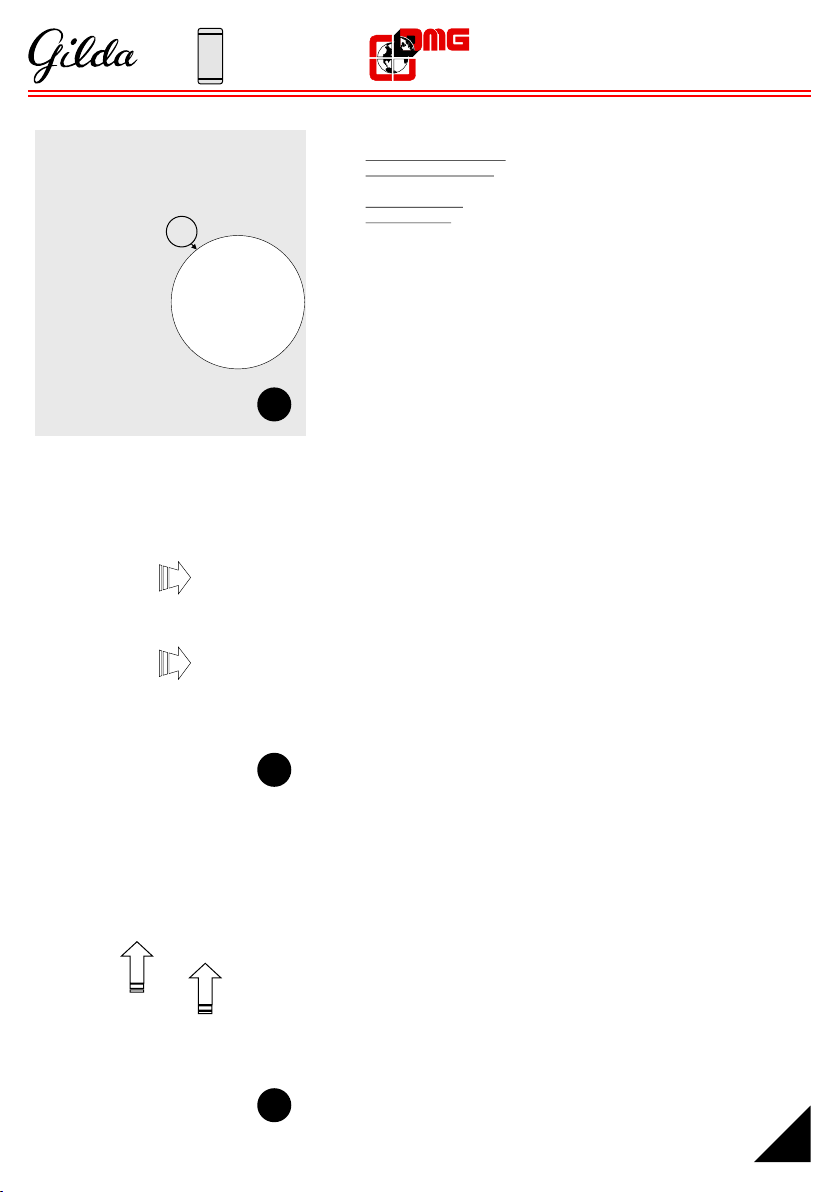
I) Dopo aver verificato con una livella che la piastra sia verticale, prendere i
riferimenti per i 2 fori di fissaggio.
GB) After levelling the plate to the floor, mark the references for the 2 fixing holes.
7
I) Rimuovere la piastra ed eseguire i fori ripetendo le fasi 1 e 2.
GB) Remove the plate and drill the holes repeating steps 1 and 2.
I) Riagganciare la piastra e fissare le viti.
Per fissaggio su stipite utilizzare le viti autofilettanti (B, pg.4)
Per fissaggio a muro utilizzare le viti (A, pg.4) ed i tasselli (D, pg.4)
GB) Fix again the plate and tighten the screws.
For frame fixing use the self-tapping screews (B, pg.4)
For wall fixing use the screws (A, pg.4) and the anchor (D, pg.4)
9
I) Inserire la testata inferiore (G, pg.3) sul supporto e serrare la vite (C, pg.3)
con l’apposito inserto Torx (F, pg.3)
GB) Enter the end piece (G, pg.3) in the support and fasten the screw (C, pg.3)
with the Torx fixing tool (F, pg.3).
65
100
9
1
1.4) Montaggio orizzontale
Horizontal fixing
I)
effettuato il foro.
GB) Mark the fixing hole reference.
Dopo aver preso il riferimento marcare il punto dove verrà
0,5 ÷ 0,9 mm
0,9 ÷ 1,2 mm
1,2 ÷ 1,5 mm
1,5 ÷ 1,9 mm
Ø 2,95 mm
Ø 3,10 mm
Ø 3,25 mm
Ø 3,50 mm
Tab.1
1,9 ÷ 2,7 mm Ø 3,60 mm
2
I)
Per fissaggio su stipite il diametro del foro cambia in base allo
spessore dello stesso (vedi Tab.1)
Per fissaggio a muro il foro è di diametro 6 mm.
GB) Drill the hole.
For frame fixing the hole diameter depends on the frame
thickness (see Table 1).
For wall fixing the hole diameter is 6 mm.
Realizzare il foro.
Ø foro
Ø hole
Spessore stipite (metallo)
Frame thickness (metal)
65/100
10
3
I) Fissare il fungo di ancoraggio (E, pg.4)
Per fissaggio su stipite utilizzare la vite autofilettante (B, pg.4)
Per fissaggio a muro utilizzare la vite (A, pg.4) e il tassello (D,
pg.4)
GB) Enter the fixing hook (E, pg.4)
For frame fixing use the self-tapping screw (B, pg.4)
For wall fixing use the screw (A, pg.4) and the anchor (D, pg.4)
4
I) Accostare la piastra alla parete facendo combaciare l’asola al
fungo di ancoraggio.
GB) Approach the plate to the wall matching the fixing hole with the
fixing hook.
5
I) Spingere la pulsantiera orizzontalmente sino all’arresto.
GB) Push the plate towards the fixing hook till it doesn't move.
65/100