DMS Q31 User manual

DM-System GmbH, Heid 14/3, 77855 Achern, +49 78418310590
www.dm-system.eu

Operating Manual / Spare Parts
CONTENT
1. SAFETY INSTRUCTION ............................................................................................................ 3
1.1 Personal Safety .................................................................................................................... 3
1.2 Work Area Safety ................................................................................................................ 4
1.3 Power Tool Use And Care ................................................................................................... 4
1.4 Battery Tool Use And Care ................................................................................................. 4
1.5 Hazards of Incorrect Operation ........................................................................................... 5
1.6 Straps Dispenser .................................................................................................................. 5
1.7 Welding Effects ................................................................................................................... 5
1.8 Correct Strap Cutting .......................................................................................................... 6
1.9 Regular Maintenance .......................................................................................................... 6
2. TECHNICAL PARAMETERS ..................................................................................................... 6
2.1 Machine Introduction .......................................................................................................... 6
2.2 Dimensions.......................................................................................................................... 7
2.3 Strap Specification .............................................................................................................. 7
2.4 Strap Strength ...................................................................................................................... 7
2.5 Working Temperature .......................................................................................................... 7
3. ATTACHMENT ............................................................................................................................ 7
3.1 Battery Specification ........................................................................................................... 7
3.2 Charger Specification .......................................................................................................... 8
3.3 One Set of Tool Kit For Free ............................................................................................... 8
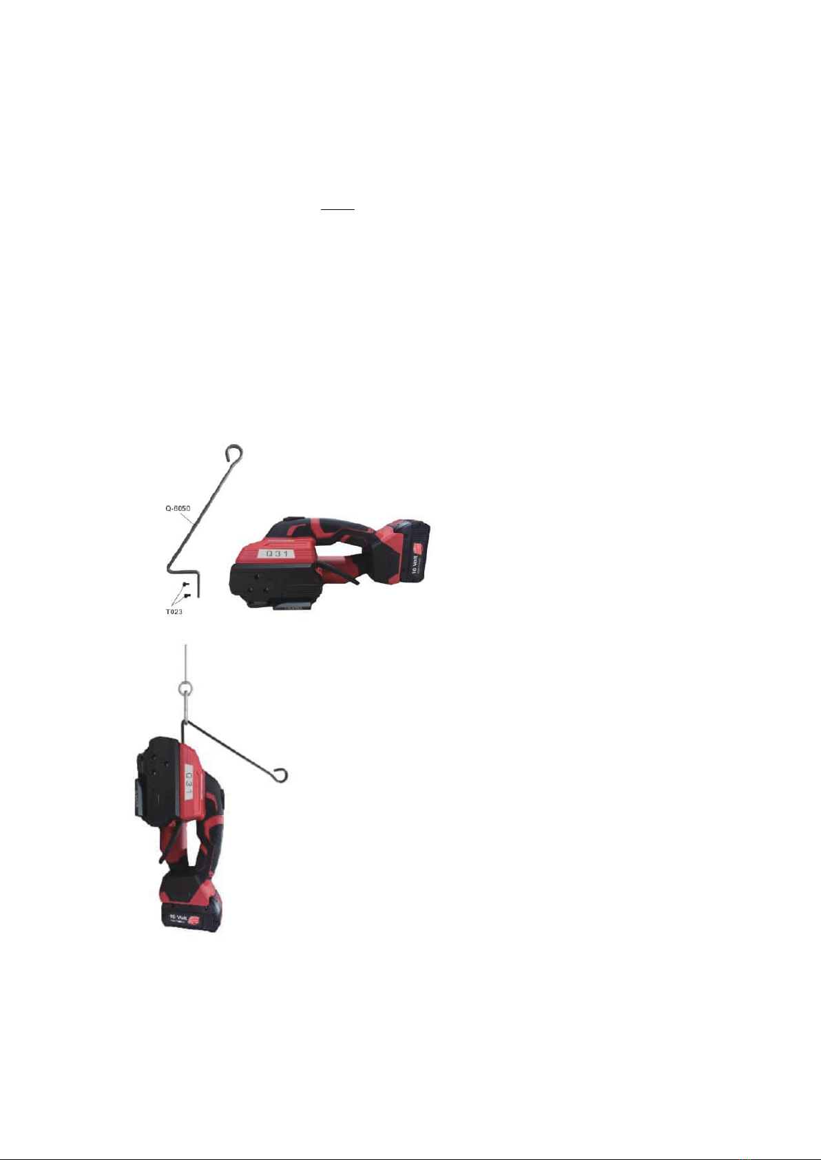
3.4 Suspension System(optional) .............................................................................................. 8
4. MACHINE APPEARANCE AND OPERATING PANEL ........................................................... 9
5. OPERATION STEPS .................................................................................................................. 10
5.1 Installation ......................................................................................................................... 10
5.2 Operation Function Description ........................................................................................ 11
5.2.1 Operation Panel And Buttons ................................................................................. 11
5.2.2 Basic Settings ......................................................................................................... 13
5.2.3 Strapping Operation Steps ...................................................................................... 15
5.2.4 Operation Methods for Three Modes ..................................................................... 16
5.2.5 Operation Essentials For Three Modes .................................................................. 17
5.3 Strapping Effect and Adjustment ...................................................................................... 18
5.3.1 Strap Welding Effect Judgment .............................................................................. 18
5.3.2 Appropriate Parameter Adjustment ........................................................................ 18
5.3.3 Reference for Tension Force (Unit: N) ................................................................... 19
6. WIRING DIAGRAM .................................................................................................................. 20
7. COMMON FAULT INDICATION AND TROUBLESHOOTING ............................................ 20
7.1 Machine Fault Code Description ...................................................................................... 21

7.2 Common Faults and Troubleshooting ............................................................................... 21
8. REPLANCEMENT OF WEARING PARTS .............................................................................. 22
9. SPARE PARTS LIST .................................................................................................................. 23
10. EXPLODED VIEW OF SPARE PARTS(需要替换清晰图片) ................................................ 27
1. SAFETY INSTRUCTION
Read all safety warnings and all instructions.
Failure to follow the warnings and instructions may result in electric shock, fire and/or
serious injury.
Save all warnings and instructions for future reference.
The term "power tool" in the warnings refers to your mains-operated (corded) power tool or
battery-operated (cordless) power tool.
1.1 Personal Safety
Stay alert, watch what you are doing and use common sense when operating a power
tool. Do not use a power tool while you are tired or under the influence of drugs, alcohol
or medication. A moment of inattention while operating power tools may result in serious
personal injury.
Use personal protective equipment. Always wear eye protection. Protective equipment
such as dust mask, non-skid safety shoes, hard hat, or hearing protection used for
appropriate conditions will reduce personal injuries.
Prevent unintentional starting. Ensure the switch is in the off-position before connecting
to power source and/or battery pack, picking up or carrying the tool.
Carrying power tools with your finger on the switch or energising power tools that have
the switch on invites accidents.
Remove any adjusting key or wrench before turning the power tool on. A wrench or a
key left attached to a rotating part of the power tool may result in personal injury.
Do not overreach. Keep proper footing and balance at all times. This enables better
control of the power tool in unexpected situations.
Dress properly. Do not wear loose clothing or jewellery. Keep your hair, clothing and
gloves away from moving parts. Loose clothes, jewellery or long hair can be caught in
moving parts.
If devices are provided for the connection of dust extraction and collection facilities,
ensure these are connected and properly used. Use of dust collection can reduce dust-
related hazards.
The operators must be trained strictly and correctly, and read & understand the
operation instructions of the machine correctly. If the operation instructions are not
followed or the straps is placed incorrectly, the straps will be damaged and the operator will
be injured.
Before getting start with the machine,please keep your fingers away from the tension

and cutting area of the machine.
Do not use the bonded straps to carry, drag or suspend the heavy object, which may
cause accidents.
1.2 Work Area Safety
Keep work area clean and well lit. Cluttered or dark areas invite accidents.
Do not operate power tools in explosive atmospheres, such as in the presence of
flammable liquids, gases or dust. Power tools create sparks which may ignite the dust or
fumes.
Keep children and bystanders away while operating a power tool. Distractions can cause
you to lose control.
Do not operate the machine in a narrow space.
1.3 Power Tool Use And Care
Do not force the power tool. Use the correct power tool for your application. The correct
power tool will do the job better and safer at the rate for which it was designed.
Do not use the power tool if the switch does not turn it on and off. Any power tool that
cannot be controlled with the switch is dangerous and must be repaired.
Disconnect the plug from the power source and/or the battery pack from the power tool
before making any adjustments, changing accessories, or storing power tools. Such
preventive safety measures reduce the risk of starting the power tool accidentally.
Store idle power tools out of the reach of children and do not allow persons unfamiliar
with the power tool or these instructions to operate the power tool.
Power tools are dangerous in the hands of untrained users.
Maintain power tools. Check for misalignment or binding of moving parts, breakage of
parts and any other condition that may affect the power tool’s operation. If damaged,
have the power tool repaired before use. Many accidents are caused by poorly maintained
power tools.
Keep cutting tools sharp and clean. Properly maintained cutting tools with sharp cutting
edges are less likely to bind and are easier to control.
Use the power tool, accessories and tool bits etc. in accordance with these instructions,
taking into account the working conditions and the work to be performed. Use of the
power tool for operations different from those intended could result in a hazardous situation.
1.4 Battery Tool Use And Care
Environmental Protection. Please don't discard or burn the waste batteries at will, causing
environmental pollution. If you don't know how to deal with it, please consult the supplier.Be
sure to use the original battery to ensure safety.
Do not disassemble the battery. Please store the battery in a dry and frost resistant room.
Storage temperature should not be higher than 50℃, please keep dry all the time.

Do not charge the waste batteries. If you find that the battery charging is abnormal, please
do not charge it by force and replace it with a new one to avoid accidents.
Recharge only with the charger specified by the manufacturer. A charger that is suitable
for one type of battery pack may create a risk of fire when used with another battery pack.
Use power tools only with specifically designated battery packs. Use of any other battery
packs may create a risk of injury and fire.
When battery pack is not in use, keep it away from other metal objects, like paper clips,
coins, keys, nails, screws or other small metal objects, that can make a connection from
one terminal to another. Shorting the battery terminals together may cause burns or a fire.
Under abusive conditions, liquid may be ejected from the battery; avoid contact. If
contact accidentally occurs, flush with water. If liquid contacts eyes, additionally seek
medical help. Liquid ejected from the battery may cause irritation or burns.
1.5 Hazards of Incorrect Operation
Incorrect operation, excessive tension, improper use of packing straps, sudden loss of
tension force due to loading of sharp objects, or breakage of straps may eventually lead
to:
The operator falling down as a result of out of balance.
Personal harm as a result of the tool and the strap whipping out to the operator quickly.
Attention:
a. If the load object is sharp, please add edge protection between the strap and the object.
b. Please wrap the packing straps around the object correctly.
c. In the process of operation, the operator should stand beside the machine and the strap,
instead of in front and back of the machine and the strap. If the operator operates the
machine by standing in a straight-line position with the tool, he may be injured by the
machine or the strap that strikes forward or backward towards him due to improper
operation. Keep away from bystanders during operation. Please use a strap of qualified
quality recommended in this manual. A qualified strap shall have suitable width,
thickness and strength. Unqualified straps may result in strap breakage during strap
tensioning, causing hazards.
1.6 Straps Dispenser
Please use professional straps dispenser to work with the machine. After finished the
operation, please fold the end of the strap into the straps dispenser.
1.7 Welding Effects
When it is found that the straps welding joint is unqualified(refer to 5.3 for the welding
joint standard), please cut off the strap and operate again.
Unqualified strap welding may lead to unsecure strapping, which may cause serious
damage during shipping process, bringing a safety hazard.

1.8 Correct Strap Cutting
Please cut off the strap with a suitable cutting tool and ensure a safe distance between
the strap and the operator. Do not stand in a same straight line as the strap, and stay away
from the loose direction of the strap, to prevent the operator from being injured by the
bounced strap due to sudden breakage of the strap.
Please use professional tools for cutting straps. Hammers, pliers, hacksaws, axes, etc. are
not allowed.
1.9 Regular Maintenance
Have your power tool serviced by a qualified repair person using only identical
replacement parts. This will ensure that the safety of the power tool is maintained;
Regularly maintain the tool to keep it in a good working condition;
Regularly check for broken or worn parts. If there are broken or worn parts, please replace
the parts in time before using it;
It is recommended to clean the machine regularly (every day) if it is used in a dirty
environment. Remove impurities such as debris in the tensioning and welding areas of the
tool with an air gun(or other dust extraction tool), and observe it with naked eyes at the same
time. If the tool is obviously damaged, please repair it and replace parts in time;
The battery needs to be charged every six months if it is not used in a long time;
Most parts of the tool need to be replaced and repaired when the number of strapping
beats reaches more than 100,000 to avoid personal injury caused by tool failure;
Please consult the supplier if you need to purchase spare and accessory parts;
Do not modify the strapping machine without permission, otherwise it may cause
personal injuries.
2. TECHNICAL PARAMETERS
2.1 Machine Introduction
Q31 series electric battery powered strapping machine has been improved greatly in
functions, performance and appearance after continuous tests and improvements by our R&D
team. It overperforms competitors' similar machine in quality. Theoretically, up to 700 strap beats
can be achieved for a battery charging, the maximum tension force can reach 2800N (the direct
tension force of strap tension wheel can reach 4200N), and the welding time is as short as 1s.
Working modes: Fully Automatic (AUT), Semi-Automatic (SEM), Manual (MAN).

2.2 Dimensions
Length: 335mm
Width: 145mm
Height: 145mm
Weight(without battery & charger): 3.45kg
Battery weight: 0.6kg
2.3 Strap Specification
Strap material: Flat or Embossed PET(polyester) or PP (polypropylene)strap.
Strap width: 13mm-16mm;Strap thickness: 0.5-1.2mm
Please choose a strap with an appropriate size according to the strapping tool you purchased.
2.4 Strap Strength
Tension: 400N-2800N(adjustable,the tension force of the tension wheel can reach 4200N).
Tightening speed: 100-200mm/s.
Welding strength: About 75-80% of the strength of PET Strap. (depending on the quality of the
straps)
2.5 Working Temperature
The ambient air temperature is between 5 ℃ and 45 ℃.
The optimum operating temperature is between 15 ℃ and 20 ℃.
3. ATTACHMENT
Please use the accessories/parts and maintenance tools required in this operation manual. It
may cause hurt if you using the unfit accessories/parts/maintenance tools.
3.1 Battery Specification
If you need to purchase the battery in your local market, please refer to the following battery
parameters and specifications:
Model: lithium battery
Voltage: 18V
Capacity: 5.0A/h (4.0A/h optional)

3.2 Charger Specification
Standard Chargers:
Input: 230V - 50/60Hz, 75W (110V optional)
Output: 10.8V-18V Max DC
3.5A
Charging time:
Lithium batteries 5.0A/h (4.0A/h): about 90 minutes.
3.3 One Set of Tool Kit For Free
3.4 Suspension System(optional)
Figure 1: Selection 1 of suspension position during operation
Figure 2: Selection 2 of suspension position during operation

4. MACHINE APPEARANCE AND OPERATING PANEL

Light Indicates
Blue Light Normal Working
Red Light Flash The battery is low, please charge it
Red Light ON Machine failure, please power it off and check
Purple Light ON Work Completion
5. OPERATION STEPS
5.1 Installation
Please don't expose the machine in the rain or wet environment!
For the sake of safety, the battery is not charged full when delivered.
Please charge the battery before use. Please refer to the attached battery charger manual.
Installation/Disassembly/Charging of battery:
The battery should be disassembled and assembled following the direction shown in the
figure. When removing the battery, press the red button and move it out.
When the battery is inserted, the battery status will be displayed for a short time.
The battery power status is displayed by the indicator lights:
Flashing green light: it means the battery is being charged
Green light on: it means the battery on the charger is fully charged
Battery Installation:
Take out the lithium battery in the
packing box and install it as shown in the
figure on the right. When the battery is
inserted, the power status light will be
displayed for a short time.

Battery Disassembly:
Remove the battery following the
direction shown in the figure. When
removing the battery, move it out while
pressing and holding the red button, as
shown in the right figure.
Battery Charging:
Insert the battery to be charged into the
charger slot and plug it into a power
supply, as shown in the figure on the
right
!Warning:
Insufficient battery power may lead to insufficient welding of the packing straps
Please cut off the strap if the strap welding is not enough!
The battery must be charged before using the machine again.
5.2 Operation Function Description
5.2.1 Operation Panel And Buttons
Start preparation:
1. Operation panel unlocking and locking:
Plug in the power supply (battery), and the machine is in the locking state, at this time any
button on the operation panel is invalid.
Unlocking Method for the Operation Panel: Press the button DEC (for about 2s), and then
press the Welding button B to unlock it after hearing a sound of Beep.
After parameters are set, you can also press the button DEC for 2s, and then press the
Welding button to lock the operation panel after hearing a sound of Beep.
Note: The machine will enter the locking state again if no operation is performed within
30s after the tool is unlocked.
2. Waking-up from the sleep state:

The machine will enter the sleep state if no operation is carried out within 120s after the
machine is unlocked, and all the indicator lights go out. All buttons will be invalid, except the
button Tensioning A1. To wake up the tool, short press the button Tensioning A1 to restore it to the
standby mode.
At this time, the machine can work normally. If it is necessary to modify the previously set
parameters, please refer to the "Operation panel unlocking", unlocking the operation panel and
then modifying the parameters.
Mode selection(MODE) and working
status indicator:
Operation mode selector (MODE):
There are three operation modes:
Manual(MAN), Semi-automatic(SEM)
and Fully automatic(AUT).
The corresponding indicator light will be
on when a mode is selected, and indicator
lights of different colors mean different
working status.
Status indicator lights:
Blue light always-on: means the tool is
normal, standby;
Red light flashing: means insufficient
power, indicating the battery has to be
charged;
Red light always-on: means tool failure,
please power it off and check;
Purple light on for a short time: indicates
completion of the packing work
Tension force setting(SET):
1
-
9 Grades; 400N
-
2800N
Welding time setting(INC&DEC):
Used to set a welding time, INC is to
increase time, and DEC to shorten time,
interval value: 0.5
-
3.5 seconds.
Tensioning mode selection:
Normal Mode H: The blue indicator light
is on;
Soft Mode L: The yellow indicator light is
on.
Battery indicator:
Displays the remaining battery capacity
(all light on means the battery full
charged.)
Buttons:
Button A: Tension Button
Button B: Welding Button

Rocker lever/Handle:
Holding up the rocker lever, you can lift
the tension wheel; retract the strap or stop
the machine in an emergency.
5.2.2 Basic Settings
Mode
selection(MODE)
After the operation
panel unlocked, you
can cycle to select a
mode you need by
short pressing the
button MODE.
Manual mode (MAN): Tensioning function and welding
function will be operated separately. Press and hold the button
Tensioning A until the set tension force is reached and then
press the button Welding B for manual strap welding & cutting
.
Semi automatic mode (SEM): Long press the button
Tensioning A, and the straps will be tensioned and welded one
time.(The tension wheel will stop rotating if the button
Tensioning A is released during the tensioning process, and at
this time, the tool will start welding and cutting off the strap if
the button Welding B is pressed.)
Fully automatic mode (AUT): Short press the button
Tensioning A, and the machine will automatically tension, weld
and cut off the strap. Under this mode: The strap will be
tensioned automatically, and will be welded and cut off
automatically when the tension grade re
aches the set one.
Tension force
setting(SET)
After the operation
panel unlocked:
Adjust the strap
tension range
(Grade 1-9) by
short pressing the
button SET. The
larger the number
is, the stronger the
tension force will
be; and the weaker
on the contrary.
(Grade 1 stands
for the minimum
tension force, and
Grade 9 for the
maximum.)
The default
factory setting of
the machine is
Normal Mode H.
Long press the
Normal Mode (H- -):
Tension force range: 400-2800N (adjustable, the tension force
of the tension wheel can reach 4200N.)
Grade: 1-9
Instruction: This mode is used when objects to be strapped are
required to be strapped relatively tightly (or when a PET strap is
used).
Note: in the Normal Mode, please adjust the tension force
for your desired one by increasing the tension force from the
minimum in sequence; and avoid the maximum grade, as
the tension force at this grade is the strongest, a strap can't
bear it, which will cause personal injuries of the operator.
Soft Mode (L- -):
Tension range: 400N-1600N

button SET on the
operation panel,
and “H - -" on the
digital display will
flash for 3 times,
which means the
tool enters the
Normal Mode.
Then long press
the button SET on
the panel, and “L -
-" on the digital
display will flash
for 3 times, which
means the tool
enters the Soft
Mode.
Grade: 1-9
Note: This mode is used when objects to be strapped are
required to be strapped relatively loosely (or when a PP
strap is used).
Welding time
setting(INC&DEC)
When setting the welding time, short press the button INC to increase the welding time,
and short press the button DEC to decrease the welding time (One press means an increase
or decrease of 0.1 seconds, and
the value display interval is 0.5
-
3.5 seconds.)
Operation panel
locking(not in the
sleep state)
The machine will automatically lock its operation panel if no-operation status has lasted
for 30 seconds. Pressing any button on the operation panel will not work at this time, that
is, settings cannot be changed, but the machine can work normally. It is unnecessary to
unlock it unless it is necessary to change the settings.
An unlocking operation is required before parameter settings are changed each time.
Unlocking method: Long press the button DEC (for about 2s), and then press the button
Welding B af
ter hearing a sound of Beep.
Waking up of the
machine from the
sleep state
The machine will enter the sleep state if no-operation status has lasted for 120 seconds,
and all the indicator lights go out. All buttons will be invalid, except the button Tensioning
A1. To wake up the tool, short press the button Tensioning A1 to restore it to the standby
mode.
Query of number
of beats
(accumulative
strap beats): six
digits displayed on
the screen
You can check six digits:
After unlocking the operation panel, long press the button MODE for about 5 seconds,
and the display screen will display three digits, ones place, tens place, and hundreds place
(a decimal point at the side of the ones place) in the first page, and thousands place, ten
thousands place and hundred thousands place in the second page.
You can switch the pages in a circular manner by short pressing the button MODE.
Exit and return to the main display screen by pressing the button INC or any other button.

5.2.3 Strapping Operation Steps
a. wrap the pp/pet straps
around the object to be
packed:
The operator faces the tool,
holding the machine in his
right hand, and the machine is
on the right side of the
operator. Place the strap
around the object to be
strapped in the order of upper
side->front side->lower side-
>back side, as shown in the
figure.
! Warning: Please keep the
PP/PET strap away from oil,
grease and other dirt when
welding it, as a dirty strap
cannot be welded well.
b. Put the straps into the
machine:
After wrapping the strap
around the object to be
strapped properly, lift the
rocker lever of the machine
with your right hand, and
insert the parallel overlaid
straps into the tool smoothly
with your left hand, and then
release the rocker level.
Note: Please tension the
strap around the object as
much as possible and then
insert it into the tool, which
can reduce the strap
tensioning time of the tool,
avoiding wasting electric
energy.
c. Tension the strap:
Tension the strap to finish
the strapping operation by
referring to the Method for
Basic Settings.
Note:
Manual(MAN) and Semi-
Automatic(SEM) Mode:
Press the tension button until
the indicator light shows
purple, and the tension
protection does not affect the
next-step operation.
Automatic(AUT) Mode:
Press the tension button in a
short time and release.
!Warning: Keep the
Object(simulation)
Object(simulation)
Object(simulation)
Object(simulation)
Correct Wrapping Direction
Wrong Wrapping Direction
Proper Length of
Strap Left
Excessive Length
of Strap Left
Object (simulation)
Tension Completed

movement of the tool in
balance during the
tensioning process. Lift the
rocker lever to stop working
when an emergency stop is
required during the
tensioning process.
Therefore, do not block the
movement direction of the
strapping tool.
d.Weld and cut off the strap:
Weld and cut off the strap to
finish the strapping operation
by referring to the Method for
Basic Settings.
The purple indicator light will
be on during the welding
process.
e.Remove the machine and
complete the operation:
After the welding is finished,
the buzzer rings for 3 seconds
and stops, indicating that the
strap welding and cutting work
is completed. At this time, you
can remove the machine by
lifting the rocker lever and
moving the tool rightward and
wait for a next operation.
Remarks: 1. In the Automatic(AUT) Mode, only Steps a, b, c, e are
required.
2. Remove the battery and then install it again, if the machine
fails to work normally due to misoperation or other reasons.
3. When the strap is stuck by the machine, the battery must be
pulled out first, then cut off the strap, remove the panel screw,
and then remove the strap.
4.The tension protection function will start by pressing the
button Tensioning continuously for 8 times, and at this time, the
protection function can be cancelled by lifting the rocker lever
once.
5. Note: If the rocker lever is lifted immediately after welding,
the machine will give rapid sound alarms for 5 seconds due to a
lack of cooling time.
5.2.4 Operation Methods for Three Modes
Manual Mode (MAN): Long press the button Tensioning until the set tension grade is
reached, and the machine will stop automatically. Then press the
button Welding, and strap welding and cutting will be finished after
three short sounds of "Beep", and at this time, hold the rocker lever to
retract the strap and remove the
machine
.
Semi-Automatic(SEM): Long press the button Tensioning until the set tension grade is
reached, and the machine will automatically weld and cut off the
strap. The strap welding will be finished after three short sounds of
Object (simulation)
Strap Welding & Cutting
Completed

"Beep", and at this time, hold the rocker lever to retract the strap and
remove
the
machine
.
Fully Automatic(AUT): Short press the button Tensioning until the set tension grade is
reached, and the tool will automatically weld and cut off the strap.
The strap welding will be finished after three short sounds of "Beep",
and at this time, hold the rocker lever to retract the strap and remove
the
machine
.
5.2.5 Operation Essentials For Three Modes
Item Manual
Mode(MAN)
Semi-Automatic
Mode(SEM)
Full-Automatic
Mode(AUT)
a. Install the battery 1. Inset the charged battery into the battery slot, completed after a sound
of “Click”.
2. The display lights are ON, displaying all the previously set data, and
the blue light is always on, going to the standby mode.
b. Strapping 1. Place the strap
around the object to
be strapped.
2. Long press the
button Tensioning
for strap retraction
until your desired
tension is reached.
3. Press the button
Welding for friction
welding process, the
purple light short
on, and one long
sound of “Beep”,
the strapping
finished.
4. An emergency
stop or strap
retraction can be
achieved by lifting
the rocker lever
during the strapping
process.
5. The machine
goes into the
standby mode (the
blue light always
on).
1. Place the strap
around the object to be
strapped.
2. Long press the
button Tensioning for
strap retraction until
the set tension is
reached, and then the
machine will carry out
friction welding
process automatically,
the purple light short
on, and three short
sounds of “Beep”, the
strapping finished.
3. An emergency stop
or strap retraction can
be achieved by lifting
the rocker lever during
the strapping process.
4. The machine goes
into the standby mode
(the blue light always
on).
1. Place the strap
around the object to be
strapped.
2. Short press (releasing
immediately) the button
Tensioning for strap
retraction until the set
tension is reached, and
then the tool will carry
out friction welding
process automatically,
the purple light short
on, and three short
sounds of “Beep”, the
strapping finished.
3. An emergency stop or
strap retraction can be
achieved by lifting the
rocker lever during the
strapping process.
4. The machine goes
into the standby mode
(the blue light always
on).
c.Idle for 30 seconds 1. The operation panel of the machine will be locked with a sound of
"Beep" after 30 seconds without any operation.
2. Long press the key DEC (for about 2 seconds), and you can unlock it
by pressing the button Welding (B1) after a sound of "Beep". (If it is not
necessary to set parameters, it is not necessary to unlock the panel,
because the machine can work in this case).
3. Strapping (the same as Item b).
d.Idle for 120 seconds 1. The machine will go into the sleep state with a sound of "Beep" after
120 seconds without any operation. Any button/key is invalid, except the
button Tensioning, in this case;

2. The machine can be wakened up by pressing the button Tensioning,
and then enter the state of step a;
3. Strapping (the same as step b).
e.Red light flashing It indicates the power is low, so replace the battery or remove the battery
and charge it.
5.3 Strapping Effect and Adjustment
5.3.1 Strap Welding Effect Judgment
It is necessary to control the welding effects after each strapping, which can be judged by visual
inspection.
There are the following three situations, as shown in the figure:
Welding time & effect perfect:
The whole width of the strap is welded fully in
the strap welding area, and the welding length is
about 19mm. A little molten material is forced
out on both sides, indicating that the welding
time is appropriate.
Welding time too short:
In the strap welding area, there is no molten
material forced out on both sides or only a little
forced out on one side, and the whole strap
width is not welded, all of which indicates
insufficient welding time and insufficient
welding.
!Warning: The strap with insufficient welding
must be cut off, adjust the welding time and
operate the tool
again.
Welding time too long:
If the welding time is too long, it will lead to
strap overheating. Excessive molten material
forced out on both sides of the strap in the strap
welding area indicates welding time too long.
!Warning: The strap with excessive welding
must be cut off, adjust the welding time and
operate the tool again.
5.3.2 Appropriate Parameter Adjustment
When the strapping effect is too loose or too tensioned, and the welding time is not appropriate,
please adjust the parameters following the setting method to keep the strapping effect in the best
condition. The tool cannot be used grudgingly, especially when the welding time deviation is too
large, which may cause strap off, causing harm to the operator or products.
Machine adjustment method for different material straps(PP/PET) and different strap width:

Case 1: Machine adjustment during PP strap and PET strap conversion:
Method: Replace the cutter spring(Q-0080) on the cutter
Steps:
a. First loosen the screw(Q-T509 M4×20) on the side shield (Q-3007). Remove the left side
shield cover;
b. Loosen the screw on the cutter (Q-0078) with an Allen key, and take off the cutter;
c. Replace the pressure cutter spring(Q-0080) on the cutter: replace the pressure cutter spring
suitable for PP strap with the pressure spring suitable for PET strap. Put the cutter spring into
the corresponding hole, and then install the cutter back. After installing the cutter, tighten the
fixing screw on the cutter.
d. Then install back the side shield (Q-3007) and tighten the screws.
e. The method of replacing the PET strap cutter spring is the same as that of replacing the PP
strap cutter spring.
Note: PP strap cutter spring: long with slightly elastic force; PET strap cutter spring: short with
stronger elastic force(replacement cutter spring is included in the Kit for free).
Case 2: Machine adjustment for different strap width conversion:
Method: Replace the limit block
Steps:
a. Strap width switch from 14-16mm to 10-13mm: Install Q-0042(13mm left front strap guide
block) and Q-0053(13mm right front strap guide block), and then replace Q-0043(16mm
back strap guide block) with Q-0041(13mm back strap guide block);
b. Strap width switch from 10-13mm to 14-16mm: Remove the two parts Q-0042(13mm left
front strap guide block) and Q-0053(13mm right front strap guide block), and replace Q-
0041(13mm back strap guide block) with Q-0043(16mm back strap guide block).
5.3.3 Reference for Tension Force (Unit: N)
Gear Normal mode (H) Flexible mode (L)
1
400
400
2
900
550
3
1400
700
4
1900
850
5
2400
1000
6
2900
1150
7
3400
1300
8
3800
1450
9
4200
1600

6. WIRING DIAGRAM
7. COMMON FAULT INDICATION AND TROUBLESHOOTING
Table of contents
Popular Packaging Equipment manuals by other brands

AETNAGROUP
AETNAGROUP ROBOPAC STARBOX 50 Use and maintenance manual

EC-PACK
EC-PACK EC-JET 2000 manual

Wexxar
Wexxar BEL 507 Operation & service manual

Easypack
Easypack Shredder 084 operating manual

Signode
Signode PRHR-34 Operation, parts and safety manual

ALLpaQ Packaging Group
ALLpaQ Packaging Group Genesis Series Operator user manual