manuals.online logo
Brands
  1. Home
  2. •
  3. Brands
  4. •
  5. Dobinsons
  6. •
  7. Automobile Accessories
  8. •
  9. Dobinsons BU59-3518 User manual

Dobinsons BU59-3518 User manual

Dobinsons Springs and Suspension www.dobinsonsprings.com
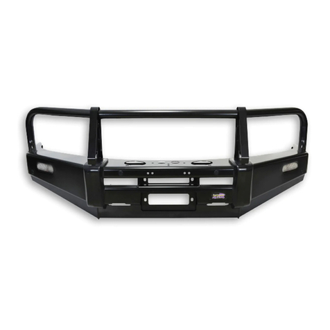
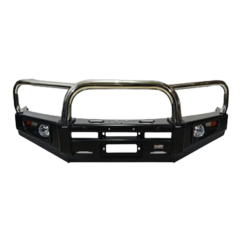
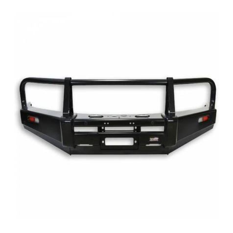
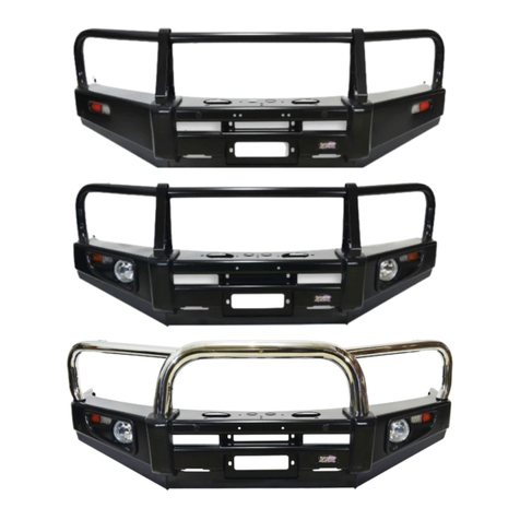
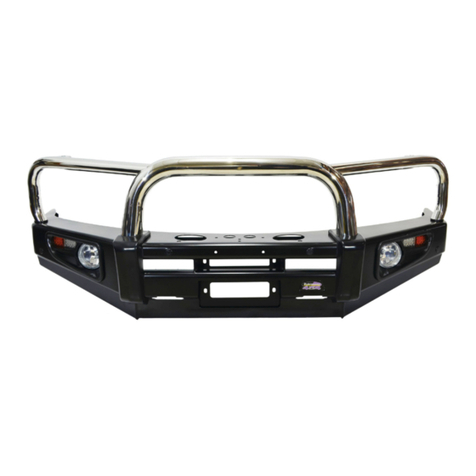
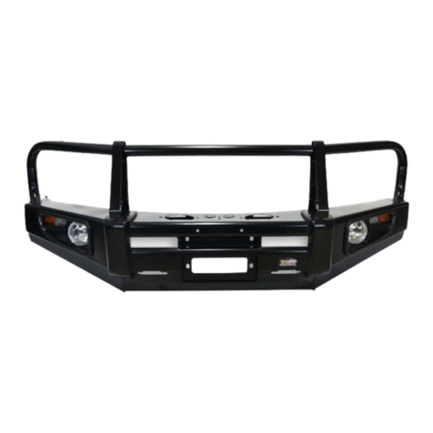
Bullbar Installation Guide
Part Number: BU59-3518, BU59-3668
Fits:
Toyota Landcruiser 80 Series
This Bullbar will take approximately 2 hours to install
Tools required are
•Spanners and socket set.
•Screwdrivers
•Pliers and side cutters
Dobinsons BULLBARS should be installed by a qualified installer and it is
the installer responsibility to ensure correct fitment.
Fully read and understand the instructions before beginning the installation
Dobinsons Springs and Suspension www.dobinsonsprings.com
Fitting Guide
1. Remove the number plate.
2. Remove the bumper bar or factory bullbar if
fitted.
3. Remove the factory tow hooks and keep
aside.
4. Install the bullbar mounting bracket and
winch mounting frame as per the diagram on
page 3.
5. Install all bolts and tighten. The factory tow
hooks can be re-fitted under the winch
mounting frame, using the original bolts.
NOTE: 80 series landcruisers are released with
slightly varying chassis heights between
models. For this reason you may have to place
packing washers between the top of the
chassis rail and inside of brackets to take up
the gap.
6. Carefully un-wrap the bulbar taking care not
to scratch it especially on the top loops.
Reinstall the number plate. If installing driving
lights to the bullbar it is easiest to install now.
7. If not installing a winch skip to step 15.
8. See the Installation section of your Dobinsons
4x4 Winch manual for specific detailed fitting
instructions. For a brief overview see the
following steps.
9. Test fit your winch to the mounting bracket
and do up loosely with the clutch handle on
the left hand side of the vehicle.
10. This may require the clutch handle and gear-
box housing to be rotated forward one or 2
bolt holes to allow easy access through the
bulbar holes. See instructions in winch user
manual.
11. Determine where the winch control box will
be located and mount the control box. See
instructions in winch user manual for control
box mounting options. If mounting to the top
of the bullbar using the supplied bracket,
check clearance of control box to grill and also
check where the wires will route as if the
wires are passing through the holes in the top
of the bullbar the control box may not be able
to be wired until the bullbar has been fitted as
below.
12. Wire the winch up as per the winch
instruction manual and bolt the winch to the
mounting bracket, ensure the mounting bolts
are not too long and tighten correctly. Route
the wires and connect to battery and also
route the breather hose.
13. Unwind some cable from the winch, and pass
the cable through the fairlead hole in the
bullbar and through the roller fairlead. This
Dobinsons Springs and Suspension www.dobinsonsprings.com
may require removing a circlip from the
fairlead and re installing once the cable is
passed through.
14. Install the roller fairlead into the bulbar.
15. Check the poly bulbar over riders, fog light
and top loop bolts are tight (Do not over
tighten the stainless steel loop mounting
bolts. Do not over tighten the poly bullbar
over riders as they will pull the over riders out
of shape).
16. With help, fit the bulbar onto the mounting
bracket and loosely fit the mounting hardware
supplied.
17. Align the bar with the vehicle into its correct
position, leaving an even gap between the top
of the bullbar wing and the bottom of the
flare of about 20mm.
18. Check for access to the clutch handle on the
winch.
19. Once you are happy with the alignment
tighten the nuts and bolts on each side.
20. Once happy with the alignment of the bullbar
drill 2 x 8mm pinning holes on each side of the
bullbar drilling through both the mounting
bracket mounting plate and bullbar mounting
plate. Fix with 8mm bolts and nyloc nuts to
keep the bullbar in its position.
21. Wire up the lights. Using a multimeter or test
light first locate the earth wire, parker positive
and indicator positive wires from the wiring
on the back of the original vehicle lights on
each side. This is easiest done by reaching in
behind the wheel arch liner and unclipping
both lights plugs for easier access.
22. Unclip the wiring from the indicator/parker
lights. Check that the wiring will be long
enough to reach the new bullbar
indicator/parker lights and extend if required.
Using the diagram at the end of this manual,
join the corresponding wires to original
vehicle wires located in the previous step. The
wires can be joined by either using good
quality snap lock crimp connectors or by
soldering. Ensure the connection is secure and
is sufficiently insulated.
23. If fitting a bullbar with fog lights, the fog lights
can be connected using the original vehicle
fog light wires if fitted. If required, cut the old
fog light wiring plugs off and cut the new fog
light wiring plugs and join. If the vehicle is not
fitted with OEM fog lights the wiring loom
supplied can be used. Follow the wiring
diagram at the end of this manual.
24. Plug the wires into the indicator, parker light
plug and fog lights. Test all lights and adjust
the position of the fog lights if required
25. Fit the under bar protection kit now with the
bolts supplied. This should sit just in front of
the tow o.e. hooks.
26. Trim the wheel arch mud guard liners back so
they are not visible from the front of the
vehicle and secure.
27. Check over all items removed during
installation.
28. IMPORTANT NOTES: It is important to inform
the customer that headlight adjustment may
also be required due to the change in ride
height. It is also important to inform the
customer that there will be a change in
vehicle handling characteristics. It is also
important to note that due to their nature fog
lights are required to provide a yellow light to
This manual suits for next models

1

Other Dobinsons Automobile Accessories manuals

Dobinsons BU59-3506 User manual

Dobinsons

Dobinsons BU59-3506 User manual

Dobinsons BU59-3541 User manual

Dobinsons

Dobinsons BU59-3541 User manual

Dobinsons BU59-3661 User manual

Dobinsons

Dobinsons BU59-3661 User manual

Dobinsons BU45-3539 User manual

Dobinsons

Dobinsons BU45-3539 User manual

Dobinsons BU59-3533 User manual

Dobinsons

Dobinsons BU59-3533 User manual

Dobinsons BU59-3545 User manual

Dobinsons

Dobinsons BU59-3545 User manual

Dobinsons BU63-3523 User manual

Dobinsons

Dobinsons BU63-3523 User manual

Dobinsons BU45-3505 User manual

Dobinsons

Dobinsons BU45-3505 User manual

Dobinsons Isuzu D-Max 2012 on User manual

Dobinsons

Dobinsons Isuzu D-Max 2012 on User manual

Dobinsons BU19-3542 User manual

Dobinsons

Dobinsons BU19-3542 User manual

Dobinsons BU59-3508 User manual

Dobinsons

Dobinsons BU59-3508 User manual

Dobinsons BU59-3660 & BU59-3510 User manual

Dobinsons

Dobinsons BU59-3660 & BU59-3510 User manual

Popular Automobile Accessories manuals by other brands

Magneti Marelli AC161 Installation instruction

Magneti Marelli

Magneti Marelli AC161 Installation instruction

FDI uEZ GUI Start here

FDI

FDI uEZ GUI Start here

JCROffroad JT Install instructions

JCROffroad

JCROffroad JT Install instructions

Rostra VOXXElectronics 250-1930 owner's guide

Rostra

Rostra VOXXElectronics 250-1930 owner's guide

TOP VEHICLE TECH GR3FORD5 installation manual

TOP VEHICLE TECH

TOP VEHICLE TECH GR3FORD5 installation manual

Safe Fleet PRIME DESIGN AR-2000-BLK manual

Safe Fleet

Safe Fleet PRIME DESIGN AR-2000-BLK manual

Skoda Fabia Combi 5J Fitting instructions

Skoda

Skoda Fabia Combi 5J Fitting instructions

Camcar 40077 Al Mounting instructions

Camcar

Camcar 40077 Al Mounting instructions

Camcar 40089 AL Mounting instructions

Camcar

Camcar 40089 AL Mounting instructions

Impac Tradesman 2000 installation manual

Impac

Impac Tradesman 2000 installation manual

DVB OFFROAD BRSB-01 installation manual

DVB

DVB OFFROAD BRSB-01 installation manual

Safari Snorkel SS385HF installation guide

Safari Snorkel

Safari Snorkel SS385HF installation guide

ULTIMATE SPEED 279746 Assembly and Safety Advice

ULTIMATE SPEED

ULTIMATE SPEED 279746 Assembly and Safety Advice

SSV Works DF-F65 manual

SSV Works

SSV Works DF-F65 manual

ULTIMATE SPEED CARBON Assembly and Safety Advice

ULTIMATE SPEED

ULTIMATE SPEED CARBON Assembly and Safety Advice

Witter F174 Fitting instructions

Witter

Witter F174 Fitting instructions

WeatherTech No-Drill installation instructions

WeatherTech

WeatherTech No-Drill installation instructions

TAUBENREUTHER 1-336050 Installation instruction

TAUBENREUTHER

TAUBENREUTHER 1-336050 Installation instruction

manuals.online logo
manuals.online logoBrands
  • About & Mission
  • Contact us
  • Privacy Policy
  • Terms and Conditions

Copyright 2025 Manuals.Online. All Rights Reserved.