manuals.online logo
Brands
  1. Home
  2. •
  3. Brands
  4. •
  5. Dobinsons
  6. •
  7. Automobile Accessories
  8. •
  9. Dobinsons BU59-3533 User manual

Dobinsons BU59-3533 User manual

Dobinsons Springs and Suspension www.dobinsonsprings.com
Bullbar Installation Guide
Part Number: BU59-3533 & BU59-3688 & BU59-3696
Fits:
Toyota Landcruiser 200 Series Facelift Models
This Bullbar will take approximately 3 hours to install
Tools required are
•Spanners and socket set.
•Screwdrivers
•Pliers and side cutters
Dobinsons BULLBARS should be installed by a qualified installer and it is
the installer responsibility to ensure correct fitment.
Fully read and understand the instructions before beginning the installation
Dobinsons Springs and Suspension www.dobinsonsprings.com
Fitting Guide
1. Remove the number plate.
2. Remove the grill by removing the bolts in the
top and bottom, and then un-clipping the
lower rectangular clips and the clips on the
side. The side clips are quite difficult as they
are hidden.
3. Remove the plastic protective plates
underneath the OE bumper.
4. Remove the screws and scrivets on the OE
bumper. They are located on the bottom,
along the top and at the back on the inside of
the wheel arch.
5. Now starting from the wheel arch carefully
unclip the bumper then unclip underneath
each headlight and carefully remove.
6. With the bumper off you can now remove the
foam strip. Then remove the aluminium
bumper mount.
7. Remove the factory bumper mounts and tow
hooks.
8. Remove the rubber flap at the bottom on the
right hand side, then trim the plastic guard as
shown to accommodate the bullbar mounting
bracket.
9. Install the bulbar mounting bracket with the
fastening hardware supplied, ensuring it is
central. The tow hooks are re-installed under
the bracket.
10. Carefully un-wrap the bulbar taking care not
to scratch it especially on the top loops.
Reinstall the number plate. If installing driving
lights to the bullbar it is easiest to install now.
11. If not installing a winch skip to step 21.
12. See the Installation section of your Dobinsons
4x4 Winch manual for specific detailed fitting
instructions. For a brief overview see the
following steps.
13. Test fit your winch to the mounting bracket
and do up loosely with the clutch handle on
the left hand side of the vehicle.
Dobinsons Springs and Suspension www.dobinsonsprings.com
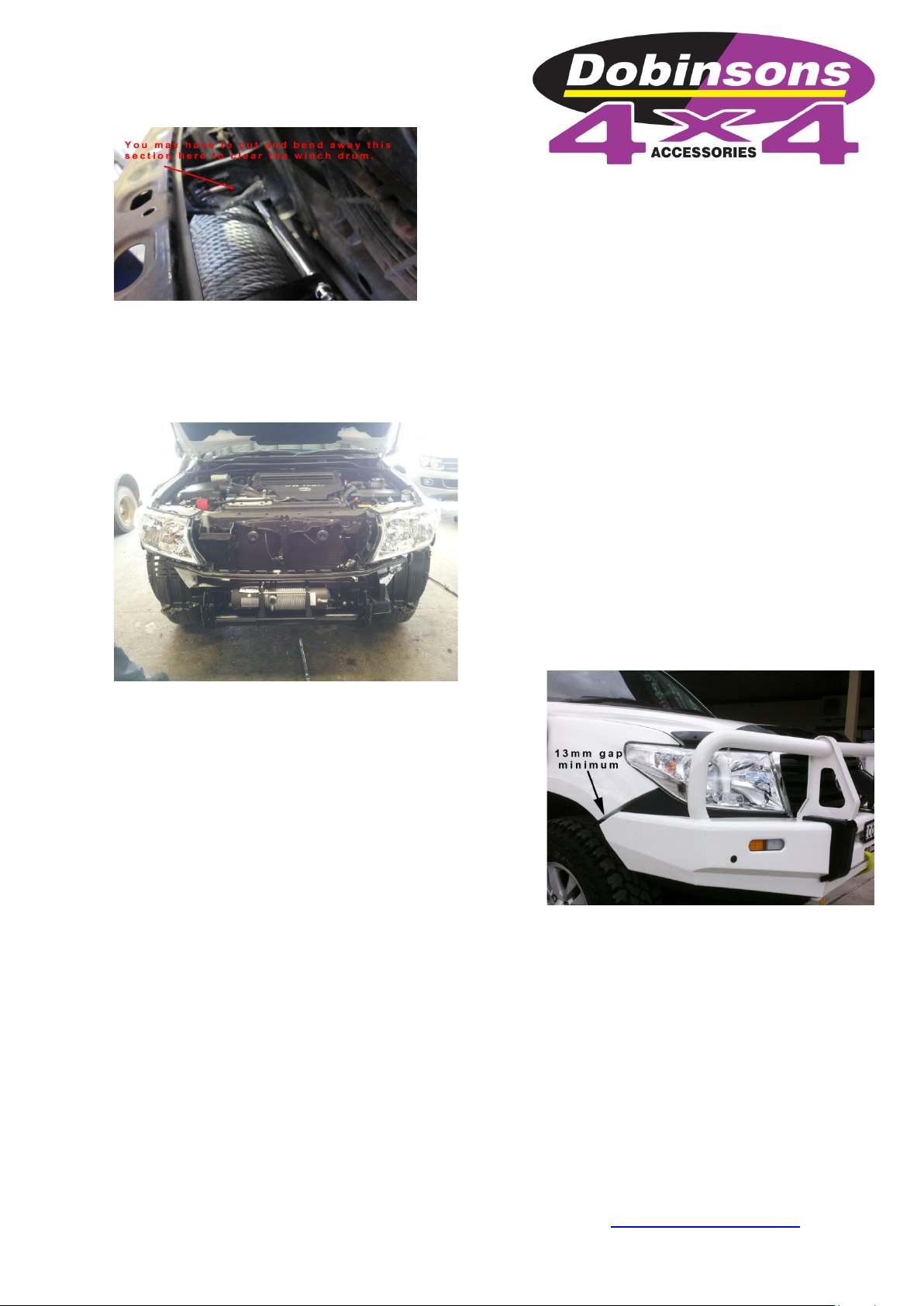
14. You may have to cut and bend the centre
brace to allow clear the winch drum as seen
below.
15. This may require the clutch handle and gear-
box housing to be rotated forward one or 2
bolt holes to allow easy access through the
bulbar holes. See instructions in winch user
manual.
16. Determine where the winch control box will
be located and mount the control box. See
instructions in winch user manual for control
box mounting options. If mounting to the top
of the bullbar using the supplied bracket,
check clearance of control box to grill and also
check where the wires will route as if the
wires are passing through the holes in the top
of the bullbar the control box may not be able
to be wired until the bullbar has been fitted as
below.
17. Wire the winch up as per the winch
instruction manual and bolt the winch to the
mounting bracket, ensure the mounting bolts
are not too long and tighten correctly. Route
the wires and connect to battery and also
route the breather hose.
18. Reinstall the grill and top cover.
19. Unwind some cable from the winch, and pass
the cable through the fairlead hole in the
bullbar and through the roller fairlead. This
may require removing a circlip from the
fairlead and re installing once the cable is
passed through.
20. Install the roller fairlead into the bulbar.
21. Check the poly bulbar over riders, fog light
and top loop bolts are tight (Do not over
tighten the stainless steel loop mounting
bolts. Do not over tighten the poly bullbar
over riders as they will pull the over riders out
of shape).
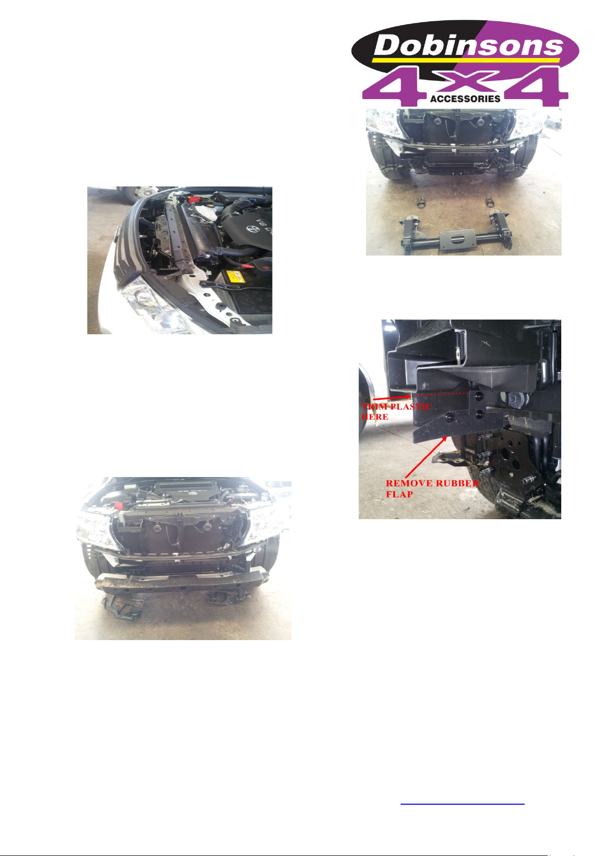
22. Fit the rubber under headlight inserts to the
bullbar, do not over tighten the bolts.
23. With help, fit the bulbar and loosely fit the
mounting hardware supplied.
24. Check for clearance on the winch control box
and access for the clutch handle and winch
controller socket.
25. Align the bulbar to the vehicle leaving at least
a 13mm gap at the bullbar wing to the bottom
of the quarter panel and tighten the mounting
bolts.
26. Once happy with the alignment of the bullbar
drill 2 x 8mm pinning holes on each side of the
bullbar drilling through both the mounting
bracket mounting plate and bullbar mounting
plate. Fix with 8mm bolts and nyloc nuts to
keep the bullbar in its position.
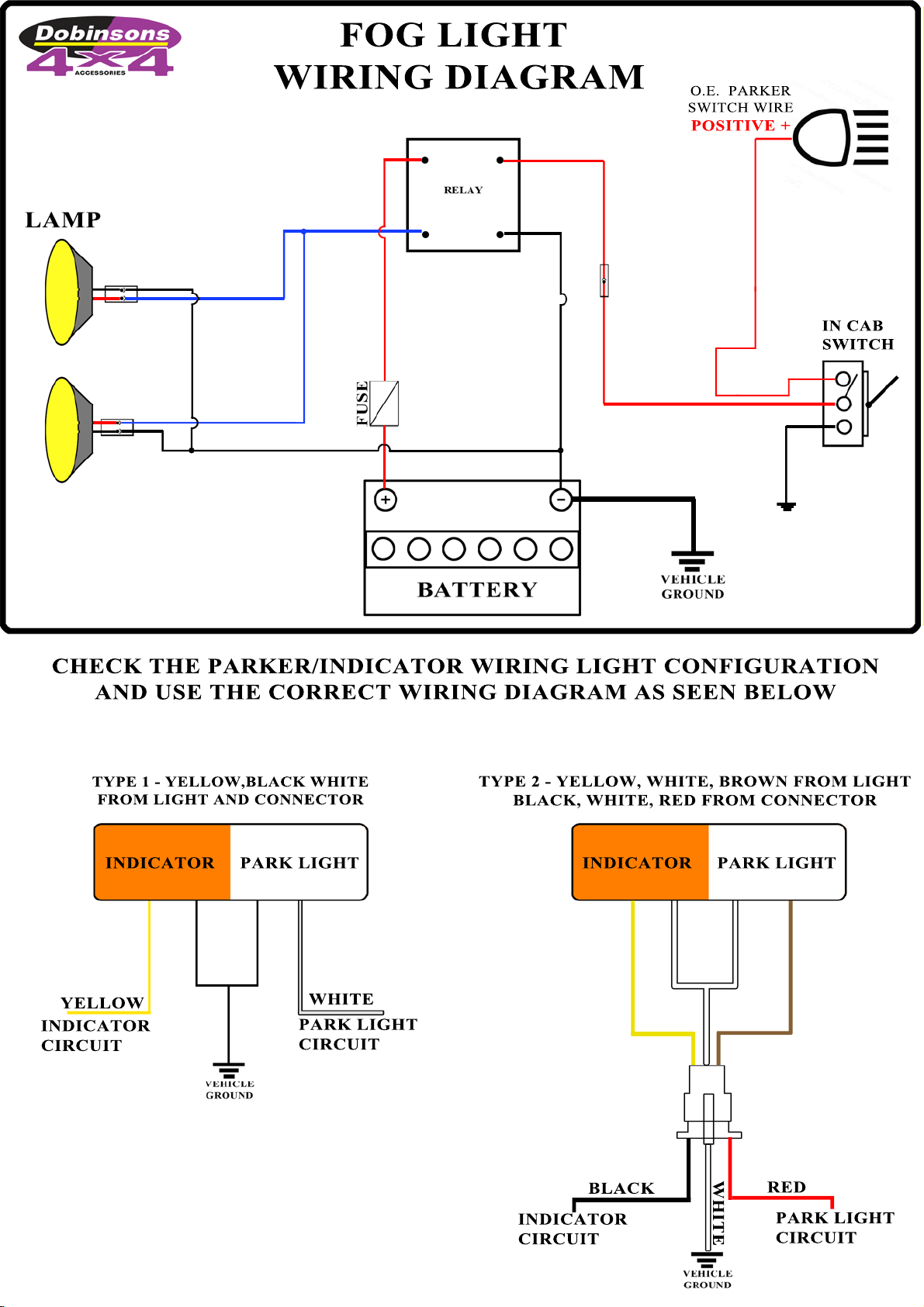
27. Wire up the lights. Using a multimeter or test
light first locate the earth wire, parker positive
and indicator positive wires from the wiring
on the back of the original vehicle lights on
each side.
Dobinsons Springs and Suspension www.dobinsonsprings.com
28. Unclip the wiring from the indicator/parker
lights. Check that the wiring will be long
enough to reach the new bullbar
indicator/parker lights and extend if required.
Using the diagram at the end of this manual,
join the corresponding wires to original
vehicle wires located in the previous step. The
wires can be joined by either using good
quality snap lock crimp connectors or by
soldering. Ensure the connection is secure and
is sufficiently insulated.
29. If fitting a bullbar with fog lights, the fog lights
can be connected using the original vehicle
fog light wires if fitted. If required, cut the old
fog light wiring plugs off and cut the new fog
light wiring plugs and join. If the vehicle is not
fitted with OEM fog lights the wiring loom
supplied can be used. Follow the wiring
diagram at the end of this manual.
30. Plug the wires into the indicator, parker light
plug and fog lights. Test all lights and adjust
the position of the fog lights if required.
31. Check over all bolts to ensure they are tight.
32. Using the fastening hardware supplied fit the
under bar protection kit.
33. Remove the plastic wheel arch section
hanging down or trim flush with the bottom
of the under protection plates and secure.
34. Check over all nuts, bolts and screws and
other items removed during installation.
35. IMPORTANT NOTES: It is important to inform
the customer that headlight adjustment may
also be required due to the change in ride
height. It is also important to inform the
customer that there will be a change in
vehicle handling characteristics. It is also
important to note that due to their nature fog
lights are required to provide a yellow light to
allow clear fog vision. For this reason
Dobinsons bullbars utilise a Halogen bulb.
Halogen bulbs generate a considerable
amount of heat to achieve the yellow colour
and this causes the air inside the fog light lens
to expand and contract. For this reason the
fog light assembly cannot be sealed and has a
small breather on the back. In some cases this
may cause condensation to form inside the
fog light. The customer may choose to seal
the lens of the fog light but must not seal the
rear breather.
Customer Copy: Bullbar Care Instructions
To ensure the surface finish quality it is recommended that the
bullbar be washed and cleaned regularly to prevent build up of
dirt and contaminants which when exposed to the elements can
degrade the surface finish. It is also recommended that the mounting fasteners on the bullbar be checked after
1000km’s. Winch servicing and care should also be carried out as per the winch instruction manual.
Stainless Loop Deluxe Bullbar Loop Care and Maintenance
(Customers with Stainless Loop Deluxe Models Only)
The top loops on your Dobinsons Stainless Loop Deluxe steel bullbar are manufactured from high quality 304 grade
stainless steel. Once formed and welded it is highly polished to provide a high gloss finish. Whilst the material is a
high quality stainless steel, like any other exterior polished surface, care and some maintenance is required to
ensure the surface finish quality.
It is recommended that the stainless loops be kept as clean as possible and is thoroughly washed and dried regularly
to prevent build up of dust and contaminants. This is especially important in coastal and high dust areas. The loops
can simply be cleaned with most regular car cleaning items like a soft sponge, car wash and a chamois, avoid strong
cleaning chemicals. Like many other highly polished exterior metals, over extended periods of time and heavy
weathering can cause some staining of the surface may occur. If this occurs the surface can be simply polished using
the following methods to remove the stains and restore the high gloss surface using simple tools and cheap readily
available polishing items.
Tools Required:
•Electric buffer or Electric drill (an electric/cordless drill is generally more convenient).
•Polishing compound – This can be supplied by Dobinsons Spring and Suspension. Please contact head office
on the details below for polish, as a specific type is used.
•Soft finishing type buffing wheel – The buffing wheel should be a soft, finishing type/Calico loose leaf style to
allow the surface to be polished to a high gloss without further marking the surface. The 2 types of discs
shown below are readily available from most hardware stores (Australian customers – Bunnings etc). The
brand below is Josco, and if purchasing a twin pack ensure that only the finishing buff is used and not the
cutting buff. DO NOT USE METAL OR HARSH BUFFING PADS.
Method
1. The stainless loops may be removed from the bullbar if this makes it easier to work on, however if using a
cordless drill this is not a necessity. If removing the loops, do not over tighten the loop retaining bolts when
re fitting.
2. Ensure the loops are first completely clean and dry.
3. Fit the polishing buff wheel to the drill or buffing tool –take note of the maximum wheel speed and rotation
direction.
4. It is recommended to follow specific instructions on the packaging of the buffing wheel for best results.
However if no instructions are provided the following guidelines can be used:
A). Carefully dress the buff wheel with the compound across the rotating wheel for a few seconds, taking
care not o apply too much compound, it is better to apply a little compound more frequently than to
overdress the buff.
B). Gently buff the work area with the buffing wheel and with light pressure move back and forth across the
job.
C). After polishing use a soft, clean, dry rag to clean the surface and inspect in the light for an even finish.
D). Once complete clean thoroughly again with a sponge and warm water.
Dobinsons Spring and Suspension
www.dobinsonsprings.com

This manual suits for next models

2

Other Dobinsons Automobile Accessories manuals

Dobinsons BU45-3539 User manual

Dobinsons

Dobinsons BU45-3539 User manual

Dobinsons BU59-3508 User manual

Dobinsons

Dobinsons BU59-3508 User manual

Dobinsons BU63-3523 User manual

Dobinsons

Dobinsons BU63-3523 User manual

Dobinsons BU59-3661 User manual

Dobinsons

Dobinsons BU59-3661 User manual

Dobinsons BU45-3505 User manual

Dobinsons

Dobinsons BU45-3505 User manual

Dobinsons Isuzu D-Max 2012 on User manual

Dobinsons

Dobinsons Isuzu D-Max 2012 on User manual

Dobinsons BU59-3545 User manual

Dobinsons

Dobinsons BU59-3545 User manual

Dobinsons BU59-3541 User manual

Dobinsons

Dobinsons BU59-3541 User manual

Dobinsons BU59-3518 User manual

Dobinsons

Dobinsons BU59-3518 User manual

Dobinsons BU19-3542 User manual

Dobinsons

Dobinsons BU19-3542 User manual

Dobinsons BU59-3660 & BU59-3510 User manual

Dobinsons

Dobinsons BU59-3660 & BU59-3510 User manual

Dobinsons BU59-3506 User manual

Dobinsons

Dobinsons BU59-3506 User manual

Popular Automobile Accessories manuals by other brands

Arkon Slim-Grip SM515 user manual

Arkon

Arkon Slim-Grip SM515 user manual

Eclipse AVN 2210p mkII Operation guide

Eclipse

Eclipse AVN 2210p mkII Operation guide

TEC Electronics CANTEC-F2-U manual

TEC Electronics

TEC Electronics CANTEC-F2-U manual

Lund Industries Headlight Flasher AT-500 installation instructions

Lund Industries

Lund Industries Headlight Flasher AT-500 installation instructions

Federal Signal Corporation SpectraLux SIFZJ FSJoin Installation maintenance and service manual

Federal Signal Corporation

Federal Signal Corporation SpectraLux SIFZJ FSJoin Installation maintenance and service manual

Reese 30886 installation instructions

Reese

Reese 30886 installation instructions

Swagman 80600 instruction sheet

Swagman

Swagman 80600 instruction sheet

Firstech, LLC. CM6000 installation manual

Firstech, LLC.

Firstech, LLC. CM6000 installation manual

DV8 OFFROAD SPEC Series Product installation manual

DV8 OFFROAD

DV8 OFFROAD SPEC Series Product installation manual

banks iDash 1.8 quick start guide

banks

banks iDash 1.8 quick start guide

Subaru F411SAN030 installation instructions

Subaru

Subaru F411SAN030 installation instructions

RACER TECH RZR STEP BAR Installation

RACER TECH

RACER TECH RZR STEP BAR Installation

Thule Kit 202 Fitting instructions

Thule

Thule Kit 202 Fitting instructions

Dynojet Power commander V installation instructions

Dynojet

Dynojet Power commander V installation instructions

Directed DS3+ installation guide

Directed

Directed DS3+ installation guide

AMP Research PowerStep 77238-01A installation guide

AMP Research

AMP Research PowerStep 77238-01A installation guide

Volvo S60 - ANNEXE 931 installation instructions

Volvo

Volvo S60 - ANNEXE 931 installation instructions

Prolux Skyline AIR S Installation maintenance and service manual

Prolux

Prolux Skyline AIR S Installation maintenance and service manual

manuals.online logo
manuals.online logoBrands
  • About & Mission
  • Contact us
  • Privacy Policy
  • Terms and Conditions

Copyright 2025 Manuals.Online. All Rights Reserved.